EP0223338A1 - Connecting arrangement for panels - Google Patents
Connecting arrangement for panels Download PDFInfo
- Publication number
- EP0223338A1 EP0223338A1 EP86306251A EP86306251A EP0223338A1 EP 0223338 A1 EP0223338 A1 EP 0223338A1 EP 86306251 A EP86306251 A EP 86306251A EP 86306251 A EP86306251 A EP 86306251A EP 0223338 A1 EP0223338 A1 EP 0223338A1
- Authority
- EP
- European Patent Office
- Prior art keywords
- panels
- upright
- arrangement according
- web
- strip
- Prior art date
- Legal status (The legal status is an assumption and is not a legal conclusion. Google has not performed a legal analysis and makes no representation as to the accuracy of the status listed.)
- Granted
Links
- 239000000463 material Substances 0.000 claims abstract description 3
- 229920003023 plastic Polymers 0.000 claims abstract description 3
- 239000004033 plastic Substances 0.000 claims abstract description 3
- 230000000903 blocking effect Effects 0.000 abstract description 2
- 238000010276 construction Methods 0.000 description 2
- 238000007688 edging Methods 0.000 description 2
- 238000001125 extrusion Methods 0.000 description 2
- 230000004048 modification Effects 0.000 description 1
- 238000012986 modification Methods 0.000 description 1
Images


Classifications
-
- E—FIXED CONSTRUCTIONS
- E04—BUILDING
- E04B—GENERAL BUILDING CONSTRUCTIONS; WALLS, e.g. PARTITIONS; ROOFS; FLOORS; CEILINGS; INSULATION OR OTHER PROTECTION OF BUILDINGS
- E04B1/00—Constructions in general; Structures which are not restricted either to walls, e.g. partitions, or floors or ceilings or roofs
- E04B1/38—Connections for building structures in general
- E04B1/61—Connections for building structures in general of slab-shaped building elements with each other
- E04B1/6108—Connections for building structures in general of slab-shaped building elements with each other the frontal surfaces of the slabs connected together
- E04B1/612—Connections for building structures in general of slab-shaped building elements with each other the frontal surfaces of the slabs connected together by means between frontal surfaces
- E04B1/6145—Connections for building structures in general of slab-shaped building elements with each other the frontal surfaces of the slabs connected together by means between frontal surfaces with recesses in both frontal surfaces co-operating with an additional connecting element
- E04B1/6158—Connections for building structures in general of slab-shaped building elements with each other the frontal surfaces of the slabs connected together by means between frontal surfaces with recesses in both frontal surfaces co-operating with an additional connecting element the connection made by formlocking
-
- F—MECHANICAL ENGINEERING; LIGHTING; HEATING; WEAPONS; BLASTING
- F16—ENGINEERING ELEMENTS AND UNITS; GENERAL MEASURES FOR PRODUCING AND MAINTAINING EFFECTIVE FUNCTIONING OF MACHINES OR INSTALLATIONS; THERMAL INSULATION IN GENERAL
- F16B—DEVICES FOR FASTENING OR SECURING CONSTRUCTIONAL ELEMENTS OR MACHINE PARTS TOGETHER, e.g. NAILS, BOLTS, CIRCLIPS, CLAMPS, CLIPS OR WEDGES; JOINTS OR JOINTING
- F16B5/00—Joining sheets or plates, e.g. panels, to one another or to strips or bars parallel to them
- F16B5/0004—Joining sheets, plates or panels in abutting relationship
- F16B5/0032—Joining sheets, plates or panels in abutting relationship by moving the sheets, plates, or panels or the interlocking key parallel to the abutting edge
- F16B5/0052—Joining sheets, plates or panels in abutting relationship by moving the sheets, plates, or panels or the interlocking key parallel to the abutting edge the interlocking key acting as a dovetail-type key
-
- Y—GENERAL TAGGING OF NEW TECHNOLOGICAL DEVELOPMENTS; GENERAL TAGGING OF CROSS-SECTIONAL TECHNOLOGIES SPANNING OVER SEVERAL SECTIONS OF THE IPC; TECHNICAL SUBJECTS COVERED BY FORMER USPC CROSS-REFERENCE ART COLLECTIONS [XRACs] AND DIGESTS
- Y10—TECHNICAL SUBJECTS COVERED BY FORMER USPC
- Y10T—TECHNICAL SUBJECTS COVERED BY FORMER US CLASSIFICATION
- Y10T403/00—Joints and connections
- Y10T403/55—Member ends joined by inserted section
- Y10T403/553—Laterally inserted section
-
- Y—GENERAL TAGGING OF NEW TECHNOLOGICAL DEVELOPMENTS; GENERAL TAGGING OF CROSS-SECTIONAL TECHNOLOGIES SPANNING OVER SEVERAL SECTIONS OF THE IPC; TECHNICAL SUBJECTS COVERED BY FORMER USPC CROSS-REFERENCE ART COLLECTIONS [XRACs] AND DIGESTS
- Y10—TECHNICAL SUBJECTS COVERED BY FORMER USPC
- Y10T—TECHNICAL SUBJECTS COVERED BY FORMER US CLASSIFICATION
- Y10T403/00—Joints and connections
- Y10T403/61—Side slide: elongated co-linear members
Definitions
- the present invention relates to a connecting arrangement for panels comprising two lateral uprights which are respectively fixed to two of the panels.
- a connecting arrangement for panels comprising a hinge with two bar portions and spring blocking means, which is capable of being mounted and fixed to the shaped edges of two contiguous panels. That arrangement is practical and functional but suffers from the disadvantage of leaving a gap between the two panels and not defining in a stable form the configuration as between the actual panels.
- the object of the present invention is to provide a connecting arrangement for panels which is simple, reliable and aesthetically acceptable and which is at the same time quick and easy to assemble and of low cost.
- the connecting arrangement for panels according to the invention is characterised by the characterising portion of the main claim.
- the connecting arrangement which is generally indicated by reference numeral 11 comprises a lateral upright 12 of a divider panel 13 which is formed in one shaped piece produced for example by extrusion and being of the same height as the panel 13.
- the upright 12 comprises a flat outside wall portion 14 integral with two side wall portions 16 and 17 parallel to each other and perpendicular to the outside wall portion 14, defining two corners 18 and 19, two internal strip portions 22 and 23 parallel to the wall portions 16 and 17, and two external strip portions 24 and 26 parallel to the wall portion 14, which define the surface for fixing of the upright to an edge 25 of the panel 13, in turn being integral with two strip portions 27 and 28 bearing sawtooth configurations.
- the edge 25 of the panel 13 is provided with longitudinal grooves 29 in which the sawtooth strip portions 27 and 28 are engaged until the edge 25 is caused to abut against the external strip portions 24 and 26.
- the external wall portions 14 is also integral with a strip portion 21 which projects towards the interior of the upright 12 until reaching the edge 25 of the panel 13 and acts as a stiffening means.
- Each corner 18 and 19 comprises a hollow support 31 and 32 which extends over the entire length of the upright 12 and is formed by a substantially cylindrical seat having a passage 33 and 34 extending to the outside of the upright 12.
- Each seat 31 and 32 extends over the entire length of the upright 12 and the two ends of the seats 31 and 32 have a portion 36 and 37 respectively which is screwthreaded over a predetermined length, as shown in Figure 3.
- a shaped connecting member 41 (see Figure 4) comprises two substantially cylindrical portions or edges 42 and 43 connected by a portion of limited thickness, formed by a plate or bar portion 40.
- the edges 41 and 42 are substantially identical and fixed with respect to the portion 40 and are made in one piece from plastics material, for example by extrusion.
- Each cylindrical edge 42 and 43 is slidably engageable into the cylindrical seats 31 and 32 ( Figure 1).
- the portion 40 (see Figure 4) is slidably engageable between the outside edges of the passages 33 and 34 (see Figure 1), which limit the axial movements of the portion 40 (see Figure 4) and thus the connecting member 41.
- the connecting member 41 may be of the shape shown in Figure 4 in which the portion 40 is rectilinear and is indicated by reference numeral 44, or the form shown in Figure 5 and Figure 6.
- the cylindrical portions 42 and 43 are identical but the form of the connecting portion 40 varies.
- the strip or bar portion indicated by 46 forms an angle of 90° while in the construction shown in Figure 6, the strip or bar portion indicated by reference numeral 47 is curved at 150°.
- the variable angle of the portion 40 permits the panels to be arranged in variable configurations.
- Figures 7, 8 and 9 show three forms of application of the connecting members 41 which permit two contiguous panels to be coplanar, as shown in Figure 7, or disposed at 90° as shown in Figure 8, or disposed at 120° as shown in Figure 9.
- the connecting members 41 ( Figures 7, 8 and 9) are provided at the ends with coaxial holes 51 co-operable with locking elements, for example screws 52 (see Figures 2 and 3) which are screwed into the corresponding screwthreaded portions 36 and 37 in such a way as structurally to connect the uprights 12 to the connecting members 41.
- the panels 13 are now rigidly connected to each other. The operator may fit a cover or edging member 53 to cover entirely the ends of the uprights 12, the panels 13 and the screws 52.
- the operator applies a slight pressure to the edging member 53 and disengages it from the uprights 12. He then unscrews the screws 52 and slides the connecting members 41 along the cylindrical seats in the uprights. The panels 13 remain free and are again ready for a fresh arrangement by means of simply changing the connecting members 41.
- the connecting arrangement 11 as described hereinbefore provides a strong, compact and functional structure which fully attains the stated object of connecting panels in variable configurations.
- connecting arrangement 11 for panels 13 may be the subject of modifications and improvements both in respect of the shape and the arrangement of the various parts thereof without departing from the scope of the invention.
Abstract
Description
- The present invention relates to a connecting arrangement for panels comprising two lateral uprights which are respectively fixed to two of the panels.
- A connecting arrangement for panels is known, comprising a hinge with two bar portions and spring blocking means, which is capable of being mounted and fixed to the shaped edges of two contiguous panels. That arrangement is practical and functional but suffers from the disadvantage of leaving a gap between the two panels and not defining in a stable form the configuration as between the actual panels.
- The object of the present invention is to provide a connecting arrangement for panels which is simple, reliable and aesthetically acceptable and which is at the same time quick and easy to assemble and of low cost.
- The connecting arrangement for panels according to the invention is characterised by the characterising portion of the main claim.
- A preferred embodiment of the invention is set forth by the following description which is given by way of non-limiting example with reference to the accompanying drawings in which:
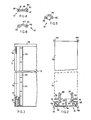
- Figure 1 is a plan view of part of the connecting arrangement for panels according to the invention, on an enlarged scale,
- Figure 2 is a second plan view of part of the arrangement according to the invention,
- Figure 3 is a longitudinal view of part of the arrangement shown in Figure 2,
- Figure 4 is a plan view of a first connecting element of the arrangement according to the invention,
- Figure 5 is a plan view of a second connecting element of the arrangement according to the invention,
- Figure 6 is a plan view of a third connecting element of the arrangement according to the invention,
- Figure 7 is a plan view of part of a first diagrammatic configuration of panels with the arrangement shown in Figure 1,
- Figure 8 is a plan view of part of a second configuration of panels with the arrangement shown in Figure 1, and
- Figure 9 is a plan view of a third configuration of panels with the arrangement shown in Figure 1.
- Referring to Figure 1, the connecting arrangement which is generally indicated by
reference numeral 11 comprises a lateral upright 12 of adivider panel 13 which is formed in one shaped piece produced for example by extrusion and being of the same height as thepanel 13. The upright 12 comprises a flatoutside wall portion 14 integral with twoside wall portions outside wall portion 14, defining twocorners internal strip portions wall portions external strip portions wall portion 14, which define the surface for fixing of the upright to anedge 25 of thepanel 13, in turn being integral with twostrip portions edge 25 of thepanel 13 is provided withlongitudinal grooves 29 in which thesawtooth strip portions edge 25 is caused to abut against theexternal strip portions external wall portions 14 is also integral with astrip portion 21 which projects towards the interior of the upright 12 until reaching theedge 25 of thepanel 13 and acts as a stiffening means. - Each
corner hollow support passage seat seats portion - A shaped connecting member 41 (see Figure 4) comprises two substantially cylindrical portions or
edges bar portion 40. Theedges portion 40 and are made in one piece from plastics material, for example by extrusion. Eachcylindrical edge cylindrical seats 31 and 32 (Figure 1). The portion 40 (see Figure 4) is slidably engageable between the outside edges of thepassages 33 and 34 (see Figure 1), which limit the axial movements of the portion 40 (see Figure 4) and thus the connectingmember 41. - The connecting
member 41 may be of the shape shown in Figure 4 in which theportion 40 is rectilinear and is indicated byreference numeral 44, or the form shown in Figure 5 and Figure 6. Thecylindrical portions portion 40 varies. In the construction shown in Figure 5, the strip or bar portion indicated by 46 forms an angle of 90° while in the construction shown in Figure 6, the strip or bar portion indicated byreference numeral 47 is curved at 150°. The variable angle of theportion 40 permits the panels to be arranged in variable configurations. Figures 7, 8 and 9 show three forms of application of the connectingmembers 41 which permit two contiguous panels to be coplanar, as shown in Figure 7, or disposed at 90° as shown in Figure 8, or disposed at 120° as shown in Figure 9. - Referring in particular to Figure 7, housed in the two
uprights 12 are two connectingmembers 41, theportion 46 of which is bent at 90°, while in Figure 8 thestraight portion 44 is used and the panels are disposed at 90°, and in Figure 9 theportion 47 which is bent at 150° is employed and the panels are disposed at 120°. - The mode of operation and assembly in the three cases is substantially identical. When the position of the panels has been established: coplanar (Figure 7), at 90° (Figure 8) or at 120° (Figure 9), the operator takes the corresponding connecting
members 41 with the morecurved portion 46, thestraight portion 44 or the lesscurved portion 47, and fits thecylindrical portions hollow supports supports coaxial holes 51 co-operable with locking elements, for example screws 52 (see Figures 2 and 3) which are screwed into the correspondingscrewthreaded portions uprights 12 to the connectingmembers 41. Thepanels 13 are now rigidly connected to each other. The operator may fit a cover or edgingmember 53 to cover entirely the ends of theuprights 12, thepanels 13 and thescrews 52. - For dismantling purposes, the operator applies a slight pressure to the edging
member 53 and disengages it from theuprights 12. He then unscrews thescrews 52 and slides the connectingmembers 41 along the cylindrical seats in the uprights. Thepanels 13 remain free and are again ready for a fresh arrangement by means of simply changing the connectingmembers 41. - The connecting
arrangement 11 as described hereinbefore provides a strong, compact and functional structure which fully attains the stated object of connecting panels in variable configurations. - It will be appreciated that the connecting
arrangement 11 forpanels 13 may be the subject of modifications and improvements both in respect of the shape and the arrangement of the various parts thereof without departing from the scope of the invention.
Claims (10)
Applications Claiming Priority (2)
| Application Number | Priority Date | Filing Date | Title |
|---|---|---|---|
| IT8567791A IT1208833B (en) | 1985-09-19 | 1985-09-19 | CONNECTION DEVICE FOR PANELS |
| IT6779185 | 1985-09-19 |
Publications (2)
| Publication Number | Publication Date |
|---|---|
| EP0223338A1 true EP0223338A1 (en) | 1987-05-27 |
| EP0223338B1 EP0223338B1 (en) | 1990-03-14 |
Family
ID=11305318
Family Applications (1)
| Application Number | Title | Priority Date | Filing Date |
|---|---|---|---|
| EP86306251A Expired - Lifetime EP0223338B1 (en) | 1985-09-19 | 1986-08-13 | Connecting arrangement for panels |
Country Status (4)
| Country | Link |
|---|---|
| US (1) | US4777777A (en) |
| EP (1) | EP0223338B1 (en) |
| DE (1) | DE3669566D1 (en) |
| IT (1) | IT1208833B (en) |
Cited By (5)
| Publication number | Priority date | Publication date | Assignee | Title |
|---|---|---|---|---|
| GB2198870A (en) * | 1986-12-19 | 1988-06-22 | Courier Prod Ltd | Joining frame members, display screens |
| GB2214961A (en) * | 1988-02-20 | 1989-09-13 | Duraflex Ltd | Roof; bay window |
| GB2219036A (en) * | 1988-05-28 | 1989-11-29 | Como & Co Limited | Panel connectors |
| EP0478563A1 (en) * | 1989-01-18 | 1992-04-08 | LLOYD, Peter | Retaining wall structure for a garden bed |
| EP2982870A1 (en) * | 2014-08-06 | 2016-02-10 | Jörg Furrer | Device for mounting a panel, in particular a glass panel |
Families Citing this family (26)
| Publication number | Priority date | Publication date | Assignee | Title |
|---|---|---|---|---|
| GB8928881D0 (en) * | 1989-12-21 | 1990-02-28 | Avon Inflatables Ltd | Inflatable boat and deck therefor |
| US5291633A (en) * | 1992-07-24 | 1994-03-08 | Trumark Limited | Coupling device |
| US5502930A (en) * | 1993-12-30 | 1996-04-02 | Stellar Holdings, Inc. | Living hinge panel connector providing stackability of levels of panels |
| DE9406350U1 (en) * | 1994-04-16 | 1994-06-30 | Preform Raumgliederungssysteme | Connecting device |
| US6098249A (en) * | 1997-10-29 | 2000-08-08 | Toney; Jerry L. | Apparatus for forming controlled density fibrous pads for diapers and the other absorbent products |
| DE19844028A1 (en) | 1998-09-25 | 2000-03-30 | Preform Raumgliederungssysteme | partition wall |
| DE19844027A1 (en) | 1998-09-25 | 2000-03-30 | Preform Raumgliederungssysteme | Connecting element for connecting two components of a partition and use of such a connecting element |
| SE513282C2 (en) * | 1998-11-16 | 2000-08-14 | Dag Goeranson | Led |
| US6430778B1 (en) * | 1999-04-13 | 2002-08-13 | Ron E. King | Apparatus for hingedly connecting a cabinet door to a cabinet wall of a frameless cabinet |
| US6378172B1 (en) | 2000-08-01 | 2002-04-30 | Fabri-Craft, Inc. | Airplane container door hinge |
| US20030007831A1 (en) * | 2001-07-06 | 2003-01-09 | Lian Aaron B. | Lock with internal retainer |
| US6880297B2 (en) * | 2002-02-22 | 2005-04-19 | Robert M. Johnston | Method and apparatus for providing a modular storage system |
| SE524721C2 (en) * | 2002-07-29 | 2004-09-21 | Upglaze Hb | Fixing device for glass facades for mounting insulating glass |
| US6952861B2 (en) * | 2002-11-01 | 2005-10-11 | Manuel Ynosencio | Multiple axis continuous hinge system |
| US7653969B2 (en) * | 2005-07-27 | 2010-02-02 | Taylor Made Group, Llc | Three-piece hinge |
| US7774991B2 (en) * | 2006-10-04 | 2010-08-17 | Ground Floor Systems, Llc | Portable ground flooring systems and methods of assembling and packing same |
| DE202007016649U1 (en) * | 2007-04-02 | 2008-04-30 | Technoform Caprano Und Brunnhofer Gmbh & Co. Kg | Ladder-shaped insulating bar for a composite profile for window, door and facade elements and composite profile for window, door and facade elements |
| DE202007014504U1 (en) * | 2007-10-17 | 2009-03-05 | Ramsauer, Dieter | Rod closure with lever-shaped rod drive |
| EP2136024B1 (en) * | 2008-06-18 | 2011-11-09 | Technoform Bautec Holding GmbH | Compound profile for window, door or façade elements with pre-defined flame retardant characteristics and isolating bar for a compound profile with flame retardant characteristics |
| US8205407B2 (en) * | 2009-04-15 | 2012-06-26 | Genova Michael C | Modular decking system |
| WO2011150467A1 (en) * | 2010-06-02 | 2011-12-08 | Ikan Building Systems Pty Ltd | Panel connection assembly, building panel and building construction method utilising a panel connection assembly |
| US9913083B2 (en) * | 2010-07-15 | 2018-03-06 | Dean R. Rosendahl | Joint for extruded panels |
| US9951527B2 (en) | 2015-07-22 | 2018-04-24 | Keystone Retaining Wall Systems Llc | Patio blocks and block systems with side surface positioning and retaining structures |
| US10779420B2 (en) * | 2016-06-03 | 2020-09-15 | Crestron Electronics, Inc. | Coupling system for joining electronic equipment housings together in a rack system |
| US11466487B2 (en) * | 2017-02-28 | 2022-10-11 | Austin Hardware & Supply, Inc. | Hinged door with latch |
| US20220251833A1 (en) * | 2021-02-09 | 2022-08-11 | Abatement Technologies, Inc. | Panel containment system and related methods |
Citations (4)
| Publication number | Priority date | Publication date | Assignee | Title |
|---|---|---|---|---|
| AT222310B (en) * | 1960-05-24 | 1962-07-10 | Renzo Oddicini | Folding wall |
| FR2134174A1 (en) * | 1971-04-23 | 1972-12-08 | Pollet Sa | |
| LU65053A1 (en) * | 1972-03-27 | 1973-10-03 | ||
| EP0017509A1 (en) * | 1979-04-05 | 1980-10-15 | B Brown (Holborn) Limited | Supporting fitments |
Family Cites Families (9)
| Publication number | Priority date | Publication date | Assignee | Title |
|---|---|---|---|---|
| US2924858A (en) * | 1956-10-16 | 1960-02-16 | Couse Mfg Inc | Structural panel member |
| DE1484009A1 (en) * | 1964-02-19 | 1969-06-04 | Franz Nogossek | House in prefabricated construction, plate-shaped component for the production of this house, intermediate piece for connecting the components and method for producing the house |
| US3363383A (en) * | 1965-03-08 | 1968-01-16 | Aluminum Co Of America | Joint structures |
| US3592289A (en) * | 1968-09-06 | 1971-07-13 | Conwed Corp | Freestanding acoustical space divider |
| US3603049A (en) * | 1969-08-18 | 1971-09-07 | William C Pierce | Wall panel construction and assembly including improved edge and bottom sealing |
| US3759005A (en) * | 1971-02-16 | 1973-09-18 | Kidde & Co Walter | Panel edge and seal structure |
| CH561364A5 (en) * | 1973-04-03 | 1975-04-30 | Felix Andre | |
| US4103465A (en) * | 1977-08-25 | 1978-08-01 | Greyhound Exhibitgroup, Inc. | Modular panel display system |
| US4488833A (en) * | 1982-04-27 | 1984-12-18 | Kaiser Aluminum & Chemical Corporation | Rapidly deployed assault vehicle surfacing or trackway system |
-
1985
- 1985-09-19 IT IT8567791A patent/IT1208833B/en active
-
1986
- 1986-08-13 EP EP86306251A patent/EP0223338B1/en not_active Expired - Lifetime
- 1986-08-13 DE DE8686306251T patent/DE3669566D1/en not_active Expired - Fee Related
- 1986-09-02 US US06/902,708 patent/US4777777A/en not_active Expired - Fee Related
Patent Citations (4)
| Publication number | Priority date | Publication date | Assignee | Title |
|---|---|---|---|---|
| AT222310B (en) * | 1960-05-24 | 1962-07-10 | Renzo Oddicini | Folding wall |
| FR2134174A1 (en) * | 1971-04-23 | 1972-12-08 | Pollet Sa | |
| LU65053A1 (en) * | 1972-03-27 | 1973-10-03 | ||
| EP0017509A1 (en) * | 1979-04-05 | 1980-10-15 | B Brown (Holborn) Limited | Supporting fitments |
Cited By (6)
| Publication number | Priority date | Publication date | Assignee | Title |
|---|---|---|---|---|
| GB2198870A (en) * | 1986-12-19 | 1988-06-22 | Courier Prod Ltd | Joining frame members, display screens |
| GB2214961A (en) * | 1988-02-20 | 1989-09-13 | Duraflex Ltd | Roof; bay window |
| GB2219036A (en) * | 1988-05-28 | 1989-11-29 | Como & Co Limited | Panel connectors |
| EP0478563A1 (en) * | 1989-01-18 | 1992-04-08 | LLOYD, Peter | Retaining wall structure for a garden bed |
| EP0478563A4 (en) * | 1989-01-18 | 1992-10-07 | Peter Lloyd | Retaining wall structure for a garden bed |
| EP2982870A1 (en) * | 2014-08-06 | 2016-02-10 | Jörg Furrer | Device for mounting a panel, in particular a glass panel |
Also Published As
| Publication number | Publication date |
|---|---|
| IT8567791A0 (en) | 1985-09-19 |
| US4777777A (en) | 1988-10-18 |
| DE3669566D1 (en) | 1990-04-19 |
| IT1208833B (en) | 1989-07-10 |
| EP0223338B1 (en) | 1990-03-14 |
Similar Documents
| Publication | Publication Date | Title |
|---|---|---|
| EP0223338A1 (en) | Connecting arrangement for panels | |
| US6332657B1 (en) | Set of construction elements for furniture | |
| US3837128A (en) | Partitioning system | |
| CA1091887A (en) | Panel assemblies and components | |
| US4460147A (en) | Mounting brackets for shelves and panels | |
| EP0177639B1 (en) | Wall system | |
| CA1058372A (en) | Modular wall panel structure | |
| US5740646A (en) | Glass brick wall | |
| US4544069A (en) | Modular elements for composing frames for the construction of cabinet structures and containers for electrical, electromechanical and electronic components, for internal and external use | |
| JP2538198B2 (en) | Detachable partition system | |
| US3380768A (en) | Profile rail and corner connecting piece | |
| IE41912B1 (en) | Improvements in or relating to connection members | |
| US6615556B2 (en) | Frameless door assembly for cleanroom | |
| US4542614A (en) | Structural members with interlocked components | |
| US4443911A (en) | Device for interconnecting panels | |
| US3833279A (en) | Modular supporting assembly | |
| GB2140853A (en) | Window frame corner piece | |
| US4917528A (en) | Panel joint | |
| EP0109466A1 (en) | Adjustable structure, for example, comprising interconnected panels | |
| EP0375237A2 (en) | Picture frame | |
| GB2241877A (en) | Shelving system and components therefor | |
| US3992840A (en) | Frameless housing | |
| GB2209063A (en) | Fastener for panels | |
| US5005333A (en) | Panel-framing assembly and assembly method therefor | |
| EP0333463B1 (en) | Panel edge strips |
Legal Events
| Date | Code | Title | Description |
|---|---|---|---|
| PUAI | Public reference made under article 153(3) epc to a published international application that has entered the european phase |
Free format text: ORIGINAL CODE: 0009012 |
|
| AK | Designated contracting states |
Kind code of ref document: A1 Designated state(s): DE FR GB |
|
| 17P | Request for examination filed |
Effective date: 19871104 |
|
| 17Q | First examination report despatched |
Effective date: 19880505 |
|
| GRAA | (expected) grant |
Free format text: ORIGINAL CODE: 0009210 |
|
| AK | Designated contracting states |
Kind code of ref document: B1 Designated state(s): DE FR GB |
|
| REF | Corresponds to: |
Ref document number: 3669566 Country of ref document: DE Date of ref document: 19900419 |
|
| ET | Fr: translation filed | ||
| PLBE | No opposition filed within time limit |
Free format text: ORIGINAL CODE: 0009261 |
|
| 26N | No opposition filed | ||
| PLBM | Termination of opposition procedure: date of legal effect published |
Free format text: ORIGINAL CODE: 0009276 |
|
| STAA | Information on the status of an ep patent application or granted ep patent |
Free format text: STATUS: OPPOSITION PROCEDURE CLOSED |
|
| 27C | Opposition proceedings terminated |
Effective date: 19920920 |
|
| PGFP | Annual fee paid to national office [announced via postgrant information from national office to epo] |
Ref country code: GB Payment date: 19930730 Year of fee payment: 8 |
|
| PGFP | Annual fee paid to national office [announced via postgrant information from national office to epo] |
Ref country code: FR Payment date: 19930805 Year of fee payment: 8 |
|
| PGFP | Annual fee paid to national office [announced via postgrant information from national office to epo] |
Ref country code: DE Payment date: 19930806 Year of fee payment: 8 |
|
| PG25 | Lapsed in a contracting state [announced via postgrant information from national office to epo] |
Ref country code: GB Effective date: 19940813 |
|
| GBPC | Gb: european patent ceased through non-payment of renewal fee |
Effective date: 19940813 |
|
| PG25 | Lapsed in a contracting state [announced via postgrant information from national office to epo] |
Ref country code: FR Effective date: 19950428 |
|
| PG25 | Lapsed in a contracting state [announced via postgrant information from national office to epo] |
Ref country code: DE Effective date: 19950503 |
|
| REG | Reference to a national code |
Ref country code: FR Ref legal event code: ST |