EP0222401B1 - IC sheet cutting press - Google Patents
IC sheet cutting press Download PDFInfo
- Publication number
- EP0222401B1 EP0222401B1 EP19860115753 EP86115753A EP0222401B1 EP 0222401 B1 EP0222401 B1 EP 0222401B1 EP 19860115753 EP19860115753 EP 19860115753 EP 86115753 A EP86115753 A EP 86115753A EP 0222401 B1 EP0222401 B1 EP 0222401B1
- Authority
- EP
- European Patent Office
- Prior art keywords
- sheet
- press
- cutting
- feed
- mold
- Prior art date
- Legal status (The legal status is an assumption and is not a legal conclusion. Google has not performed a legal analysis and makes no representation as to the accuracy of the status listed.)
- Expired - Lifetime
Links
Images


Classifications
-
- H—ELECTRICITY
- H01—ELECTRIC ELEMENTS
- H01L—SEMICONDUCTOR DEVICES NOT COVERED BY CLASS H10
- H01L21/00—Processes or apparatus adapted for the manufacture or treatment of semiconductor or solid state devices or of parts thereof
- H01L21/02—Manufacture or treatment of semiconductor devices or of parts thereof
- H01L21/04—Manufacture or treatment of semiconductor devices or of parts thereof the devices having at least one potential-jump barrier or surface barrier, e.g. PN junction, depletion layer or carrier concentration layer
- H01L21/48—Manufacture or treatment of parts, e.g. containers, prior to assembly of the devices, using processes not provided for in a single one of the subgroups H01L21/06 - H01L21/326
-
- H—ELECTRICITY
- H01—ELECTRIC ELEMENTS
- H01L—SEMICONDUCTOR DEVICES NOT COVERED BY CLASS H10
- H01L21/00—Processes or apparatus adapted for the manufacture or treatment of semiconductor or solid state devices or of parts thereof
- H01L21/67—Apparatus specially adapted for handling semiconductor or electric solid state devices during manufacture or treatment thereof; Apparatus specially adapted for handling wafers during manufacture or treatment of semiconductor or electric solid state devices or components ; Apparatus not specifically provided for elsewhere
- H01L21/67005—Apparatus not specifically provided for elsewhere
- H01L21/67011—Apparatus for manufacture or treatment
- H01L21/67092—Apparatus for mechanical treatment
-
- H—ELECTRICITY
- H01—ELECTRIC ELEMENTS
- H01L—SEMICONDUCTOR DEVICES NOT COVERED BY CLASS H10
- H01L21/00—Processes or apparatus adapted for the manufacture or treatment of semiconductor or solid state devices or of parts thereof
- H01L21/67—Apparatus specially adapted for handling semiconductor or electric solid state devices during manufacture or treatment thereof; Apparatus specially adapted for handling wafers during manufacture or treatment of semiconductor or electric solid state devices or components ; Apparatus not specifically provided for elsewhere
- H01L21/68—Apparatus specially adapted for handling semiconductor or electric solid state devices during manufacture or treatment thereof; Apparatus specially adapted for handling wafers during manufacture or treatment of semiconductor or electric solid state devices or components ; Apparatus not specifically provided for elsewhere for positioning, orientation or alignment
-
- H—ELECTRICITY
- H05—ELECTRIC TECHNIQUES NOT OTHERWISE PROVIDED FOR
- H05K—PRINTED CIRCUITS; CASINGS OR CONSTRUCTIONAL DETAILS OF ELECTRIC APPARATUS; MANUFACTURE OF ASSEMBLAGES OF ELECTRICAL COMPONENTS
- H05K13/00—Apparatus or processes specially adapted for manufacturing or adjusting assemblages of electric components
- H05K13/0092—Treatment of the terminal leads as a separate operation
-
- Y—GENERAL TAGGING OF NEW TECHNOLOGICAL DEVELOPMENTS; GENERAL TAGGING OF CROSS-SECTIONAL TECHNOLOGIES SPANNING OVER SEVERAL SECTIONS OF THE IPC; TECHNICAL SUBJECTS COVERED BY FORMER USPC CROSS-REFERENCE ART COLLECTIONS [XRACs] AND DIGESTS
- Y10—TECHNICAL SUBJECTS COVERED BY FORMER USPC
- Y10T—TECHNICAL SUBJECTS COVERED BY FORMER US CLASSIFICATION
- Y10T29/00—Metal working
- Y10T29/51—Plural diverse manufacturing apparatus including means for metal shaping or assembling
- Y10T29/5136—Separate tool stations for selective or successive operation on work
- Y10T29/5137—Separate tool stations for selective or successive operation on work including assembling or disassembling station
- Y10T29/5139—Separate tool stations for selective or successive operation on work including assembling or disassembling station and means to sever work prior to disassembling
-
- Y—GENERAL TAGGING OF NEW TECHNOLOGICAL DEVELOPMENTS; GENERAL TAGGING OF CROSS-SECTIONAL TECHNOLOGIES SPANNING OVER SEVERAL SECTIONS OF THE IPC; TECHNICAL SUBJECTS COVERED BY FORMER USPC CROSS-REFERENCE ART COLLECTIONS [XRACs] AND DIGESTS
- Y10—TECHNICAL SUBJECTS COVERED BY FORMER USPC
- Y10T—TECHNICAL SUBJECTS COVERED BY FORMER US CLASSIFICATION
- Y10T29/00—Metal working
- Y10T29/51—Plural diverse manufacturing apparatus including means for metal shaping or assembling
- Y10T29/5147—Plural diverse manufacturing apparatus including means for metal shaping or assembling including composite tool
- Y10T29/5148—Plural diverse manufacturing apparatus including means for metal shaping or assembling including composite tool including severing means
- Y10T29/5149—Plural diverse manufacturing apparatus including means for metal shaping or assembling including composite tool including severing means to sever electric terminal from supply strip
-
- Y—GENERAL TAGGING OF NEW TECHNOLOGICAL DEVELOPMENTS; GENERAL TAGGING OF CROSS-SECTIONAL TECHNOLOGIES SPANNING OVER SEVERAL SECTIONS OF THE IPC; TECHNICAL SUBJECTS COVERED BY FORMER USPC CROSS-REFERENCE ART COLLECTIONS [XRACs] AND DIGESTS
- Y10—TECHNICAL SUBJECTS COVERED BY FORMER USPC
- Y10T—TECHNICAL SUBJECTS COVERED BY FORMER US CLASSIFICATION
- Y10T83/00—Cutting
- Y10T83/444—Tool engages work during dwell of intermittent workfeed
- Y10T83/463—Work-feed element contacts and moves with work
- Y10T83/4635—Comprises element entering aperture in, or engaging abutment surface on, work
Definitions
- the present invention relates to an IC (Integrated Circuit) sheet cutting press for performing a series of press cutting operations while feeding an IC sheet stepwise in which IC sheet a plurality of IC's are coupled through a lead frame.
- IC Integrated Circuit
- An IC sheet cutting press of this type is known from the document US-A-3 722 060.
- the press described therein is provided for cutting IC sheets each comprising a plurality of ICs coupled through a lead frame, and includes an IC sheet feed mechanism for feeding the respective IC sheet stepwise, as well as a plurality of press molds for performing the series of the press cutting operations, wherein said sheet feed mechanism and said plurality of press molds are provided on a common die set to constitute a single mold unit.
- this object is solved by providing an IC sheet cutting press having the features of claim 1.
- a plurality of types of press molds for performing a series of press cutting machining and an IC sheet feed mechanism for feeding IC sheets stepwise are separately detachably mounted on a common die set to constitute a single press mold unit.
- the press mold unit performs a series of press cutting machining while IC sheets are fed stepwise, thus cutting IC's from a lead frame.
- the press mold unit can be entirely exchanged with another press mold unit. Since the press molds and the IC sheet feed mechanism need not be positioned separately, replacement can be performed easily within a short period of time. In this case, if different press mold units have common fixing portions to a press table and coupling portions to a press ram, the exchange operation can be standardized and can be easily carried out by unskilled workers. As a result, the stop time of the IC cutting press can be shortened, thus minimizing reduction of the operation efficiency and realizing a high productivity.
- the IC sheet cutting press can be easily converted for machining another type of IC sheet, resulting in high compatibility.
- the press molds and the IC sheet feed mechanism are detachably mounted on the die set and can be individually exchanged. Therefore, if a plurality of types of die sets, press molds, and IC sheet feed mechanisms are prepared and are selectively combined, various press mold units can be assembled. Therefore, different press units need not be prepared for each different type of IC sheet, resulting in a low mold manufacturing cost.
- an IC processing apparatus capable of automatically performing IC sheet processing including cutting of IC's from an IC sheet for a long period of time can be realized.
- Preferred embodiments of the present invention will be described with reference to an IC sheet processing apparatus which automatically performs cutting of IC's from an IC sheet and bending of lead terminals of the cut IC's for a long period of time.
- Figures 1 to 4 show an IC sheet processing apparatus, which basically comprises an IC sheet loader A, an IC sheet cutting press B, an IC sheet bending press C, and an IC unloader D.
- IC sheet loader A a large number of magazines M each storing a large number of IC sheets S shown in Fig. 5 are stocked in a magazine stock section A1, and the IC sheets S are picked up from each magazine M one by one and fed to the IC sheet cutting press B by an IC sheet feeding section A2.
- the IC sheet cutting press B performs a series of press machining operations with respect to the IC sheet S to separate IC's therefrom, as shown in Fig. 6.
- the IC lead bending press C bends lead terminals L of the IC's separated from the IC sheet shown in Fig. 7, as shown in Fig. 8.
- the IC unloader D stores and stocks a large number of IC's after the lead bending process shown in Fig. 8 in a container CN.
- reference symbol E in Figs. 2 and 4 denotes a dust collector for collecting a punched refuse or cutting dust produced during IC sheet cutting of the cutting press B.
- a plurality of DIP (Dual-Inline-Package) type IC's are coupled to each other through a lead frame F.
- the lead frame F is formed integrally with the lead terminals L, cross bars F1, dam bars F2, and tie bars F3.
- the dam bar F2 presents flowing of resin leaked from a mold during resin molding to the distal end portions of the lead terminals.
- the tie bar F3 directly couples the IC package to the lead frame F, and serves to hold the IC's until the last step of the IC sheet cutting process, as will be described later.
- a large number of holes having different shapes and sizes are formed in the lead frame F to be used for feeding the IC sheet or for position detection.
- the IC's are cut from the IC sheet S in such a manner that the IC sheet S is fed stepwise along an IC sheet feed path T at a distance equal to an arrangement interval p of the IC's (Fig. 5) to be subjected to a series of press machining steps, i.e., resin punching, dam bar cutting, lead cutting, tie bar pinch forming, and punching steps.
- a series of press machining steps i.e., resin punching, dam bar cutting, lead cutting, tie bar pinch forming, and punching steps.
- the IC sheet loader A basically has a magazine stock section (to be referred to simply as a "stock section” hereinafter) A1 for storing the magazines M, the IC sheet feeding section A2 for picking up the IC sheets S one by one from a magazine MA located at an IC sheet pickup position TP on one end side of the stock section A1 and feeding it to the cutting press B, and a magazine returning section A3 for returning an empty magazine, from which the IC sheets S have been picked up, to the end position of the magazine array on the other end side of the stock section A1.
- reference numeral A4 denotes an operation panel.
- the IC sheet cutting press B has a press mold unit B1, as shown in Fig. 23.
- the press mold unit B1 is mounted on a table B3 of a press frame, and is driven by a press ram B2 (Fig. 4) mounted in a ram housing B4.
- the press mold unit B1 comprises a lower mold B10, an upper mold B20, and an IC sheet feed mechanism B30, and performs a series of press machining operations to cut IC's from the IC sheet S (Fig. 5) by the upper and lower molds B10 and B20 while feeding the IC sheets S stepwise by the IC sheet feed mechanism B30.
- the arrangement and operation of the respective sections of the press mold unit B1 will be described hereinafter in detail.
- the lower mold B10 is arranged in such a manner that respective dies DE1 to DE5 for press molds for performing above-mentioned series of press machining operations (i.e., resin punching, dam bar cutting, lead cutting, tie bar pinch forming, and punching) are detachably mounted on a single common die holder 110.
- press molds for performing above-mentioned series of press machining operations (i.e., resin punching, dam bar cutting, lead cutting, tie bar pinch forming, and punching) are detachably mounted on a single common die holder 110.
- the resin punching die DE1 at the first stage will be exemplified below.
- the die DE1 is mounted on a die plate 111.
- the die plate 111 is positioned by a key groove 113 in its bottom surface, a guide key 113 of the die holder 110 (Fig. 25), and a tapered metal member 114 and a fastening metal member 115 on one side of the die plate 111, and is fixed to the die holder 110 by a bolt 116 at its opposite end portion.
- the fastening metal member 115 is common to the die plates of the dies DE1 to DE3, as can be seen from Fig. 24.
- a pair of dust-sealed guide bushings 117 are arranged on the die plate 111, and are engaged with pilot pins 147 (to be described later; Figs. 30 and 32) of the upper mold B20.
- the two dies DE4 and DE5 at the latter stage are mounted on a common die plate 118, as shown in Figs. 24 and 25.
- the die plate 118 is positioned by a key groove 119, a guide key 120 (Fig. 25), and a tapered metal member 121 and a fastening metal member 122 (Figs. 24, 26, and 27) as in the die plate 111, and is fixed to the die holder 110 by a bolt.
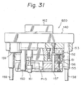
- the die plate 118 has a pair of dust-sealed bushings 123 (Fig. 24) at its two end portions, which are engaged with pilot pins 158 of the upper mold B20 (to be described later; Figs. 30 and 31).
- an air cylinder 124 and a guide rail 125 for feeding IC's cut from the IC sheet by the punching press mold (i.e., the die DE5 of the upper mold B10 and a punch PH5 of the upper mold B20) to the bending press C are arranged on the die plate 118 to be perpendicular to the IC sheet feed path T. Since the tie bar pinch forming die DE4 and the punching die DE5 are always used in this combination, they are mounted on the common die plate 118, thus allowing easy mounting and removal of these dies.
- the dies DE1 to DE5 are arranged along the IC sheet feed path T at given intervals, i.e., 1.5p or 2p shown in Fig. 6.
- each guide post 130 is fitted in a hole of the die plate 110 and is fixed by a flange 131, a retainer plate 132, and a bolt 133.
- Stopper pins 135 are provided adjacent to the three guide posts 130. These pins 135 abut against stopper pins 160 (to be described later; Figs. 30 and 31) of the upper mold B20 to define the lower dead point of the upper mold B20.
- Other stopper pins 136 are arranged adjacent to the guide posts 130. These pins 136 abut against spring-biased stopper pins 161 (to be described later; Figs. 30 and 31) of the upper mold B20.
- An air joint block 137 for supplying a vacuum pressure for drawing an IC cut by the punching die DE5 and compressed air to the air cylinder 124 for feeding IC's is arranged on one side (the left side in Fig. 24) of the die holder 110. Although a number of photosensors for detecting an IC sheet feed position are arranged on the die holder 110, a detailed description thereof will be omitted.
- FIGs 24 to 27 illustrate a state wherein a sheet guide assembly B31 of the IC sheet feed mechanism B30 (Fig. 23) is mounted on the die holder 110.
- the sheet guide assembly B31 will be described later.
- the lower mold B10 is detachably mounted on the table B3 of the cutting press B. More specifically, as shown in Figs. 24, 25, and 27, a key groove 138 is formed in the bottom surface of the die holder 110, and a pair of tapered metal members 139 are arranged on its one end side. As shown in Fig. 23, a guide key B3a and a fastening metal member B3b are fixed to the table B3 of the cutting press B to be perpendicular to each other.
- the lower mold B10 When the key groove 138 of the die holder 110 is engaged with the guide key B3a and the tapered metal member 139 is engaged with the fastening metal member B3b, the lower mold B10 can be positioned, and is fixed, such that a bolt (not shown) is screwed in a tap hole B3c of the table B3 from a bolt hole 110a (in the upper left corner in Fig. 24) of the die holder 110. Note that since the common fixing structure of the lower mold B10 with respect to the press table B3 is adopted, a compatibility with different press mold units B1 can be provided.
- a hole B3d formed in the press table B3 is a dust collecting port corresponding to the dies DE1 to DE3 of the lower mold B10.
- the dust collecting port B3d communicates with a dust collector E through a hose or tube E1, as shown in Fig. 4, so that a punched refuse or cutting dust produced by the dies DE1 to DE3 is collected through the dust collecting port B3d.
- the press B has a transparent safe cover B5.
- the cover B5 When the cover B5 is opened, not only the IC sheet cutting press B but also the entire IC sheet processing apparatus is automatically stopped.
- the upper mold B20 is arranged so that punches PH1 to PH5 for the respective press molds for performing the above-mentioned series of press machining operations are detachably mounted on a single common punch holder 140.
- the resin punch PH1 at the first stage will be exemplified below.
- the punch PH1 is mounted on a punch plate 141, which is detachably mounted on the punch holder 140 by a bolt 144 through an intermediate plate 142 and a base plate 143.
- a sheet pressing plate (or a stripper plate) 145 is mounted on the punch plate 141 by a pair of spring-biased slide pins 146 to be vertically movable, and a pair of pilot pins 147 are fixed thereto.
- the pilot pins 147 are engaged with the guide bushings 117 of the die holder 111 for the dies DE1 to DE3 of the lower mold B10 described above (Figs. 24 and 27).
- the punches PH4 and PH5 at the latter stage are mounted on a punch plate 151, as shown in Fig. 31, and the punch plate 151 is detachably mounted on the punch holder 140 by a bolt 154 (Fig. 29) through an intermediate plate 152 and a base plate 153.
- the base plate 153 is common to the punches PH4 and PH5, as shown in Fig. 30. This arrangement corresponds to that wherein the die plate 118 commonly used for the dies DE4 and DE5 of the lower mold B10.
- a sheet pressing plate (or a stripper plate) 155 is mounted on the punch plate 151 by a pair of spring-biased slide pins 156 and a pair of guide pins 157 to be vertically movable.
- a pair of pilot pins 158 are fixed to the common base plate 153, and are engaged with the guide bushings 123 of the lower mold B10 described above.
- guide bushings 159 Four guide bushings 159, three stopper pins 160, and four spring-biased stopper pins 161 are arranged on the punch holder 140. As described above, the guide bushings 159 are engaged with the guide posts 130 of the lower mold B10, and the stopper pins 160 and 161 abut against the stopper pins 135 and 136 of the lower mold B10, respectively.
- the punch holder 140 has a ram coupling member 162, which is engaged with the flange B2a (Figs. 30 and 32) at the distal end portion of the piston rod of the press ram B2 (Fig. 4) of the cutting press B.
- the upper mold B20 is vertically moved by the press ram B2, and a sheet cutting operation is performed by the dies DE1 to DE5 and the punches PH1 to PH5.
- An L-shaped lever 163 is fixed to one end portion of the punch holder 140.
- the lever 163 pushes down a sheet feed lever 220 (see Fig. 35) of the IC sheet feed mechanism B30 by utilizing downward movement of the upper mold B20, and will be described later.
- the upper mold B10 also has a large number of photosensors for position detection during IC sheet feed, a detailed description thereof will be omitted.
- the IC sheet feed mechanism B30 comprises the sheet guide assembly B31 (illustrated in a stage wherein it is mounted on the lower mold B10), a feed rod assembly B32 for feeding the IC sheet along the sheet guide assembly, and an ejector B33 for ejecting a waste sheet after IC cutting, as shown in Fig. 23.
- the sheet guide assembly B31 has a pair of guide rails 170 arranged on two sides of the IC sheet feed path T (Fig. 24), as shown in Figs. 24 to 28.
- Each guide rail 170 has a supporting rail 171 having a rectangular section, and a cover plate 172 fixed to the upper surface of the rail 171 by a screw.
- the CI sheet S is fed, with the right and left side edges of the lead frame F (Fig. 5) engaged with the guide grooves between the supporting rails 171 and the cover plates 172.
- the end portions on one side of the supporting rails 171 of the guide rails 170 extend from the lower-mold die holder 110, and constitute a sheet feed portion on which the IC sheet fed by the IC sheet feeding section A2 of the IC sheet loader A is placed.
- guide blocks 173 are mounted on the extending end portions of the supporting rails 171, and the IC sheet S is inserted from the above between the guide blocks 173 to be placed on the supporting rails 171 by the lead frame side edge portion.
- Two sheet pressing plates 174 (only one is shown) are arranged on each guide block 173.
- the sheet pressing plates 174 normally extend inwardly, and when the IC sheet S is inserted from the above, they are extended outwardly to allow insertion of the IC sheet S. After insertion of the IC sheet, the plates 174 again extend inwardly to prevent the IC sheet S from being ejected outside. Note that the IC sheet S is often bent during its manufacture. However, the sheet pressing plates 174 suppress the bending of the IC sheet to hold it flat. The bending of the IC sheet is suppressed by the guide grooves of the guide rails 170 during the subsequent stepwise feed, thus allowing satisfactory press cutting.
- the guide rails 170 are mounted on the lower-mold die holder 110 by lifters 180 at positions adjacent to their ends to be vertically movable.
- each lifter 180 has a body 181 fixed to the die holder 110, and a lift pin 182 is mounted in the body 181 by a linear ball baring 183 to be vertically movable.
- the upper end portion of the lift pin 182 is inserted in the hole of the corresponding supporting rail 171 of the guide rail 170, and the lower end portion thereof is inserted in the hole of the die holder 110, so that the guide rails 170 are biased upward by the action of a compression coil spring 184.
- a stopper plate 185 is fixed to the upper surface of the lifter body 181, and a pawl 186 fixed to the lower surface of the corresponding guide rail 170 is engaged with the lower surface of the stopper plate 185, thus defining the upper limit lift position (upper dead point) of the guide rail 170.
- the guide rails 170 are held at a level higher than that of the upper surface of the dies DE1 to DE5 in a non-press state wherein the upper mold B20 is located at its upper position.
- the guide rails 170 are pushed downward by the upper mold B20 to the level of the dies DE1 to DE5, thus performing IC sheet cutting.
- the lift operation of the guide rails 170 is associated with the IC sheet feed operation by the feed rod assembly B32.
- a large number of sensor light transmission holes for detecting the IC sheet position are formed in the supporting rails 171 and the cover plates 172 of the guide plates 170.
- a large number of elongated holes are formed in the cover plates 172 so as to allow engagement of feed pins 196 (Fig. 33) of the feed rod assembly B32 with the feed holds of the IC sheets.
- the feed rod assembly B32 has a feed rod 190 extending parallel to the guide rails 170 (indicated by imaginary lines), and feed arms 191 to 195 are mounted on the feed rod 190 to be perpendicular thereto.
- feed pins 196 extending downward are arranged on the lower surface of each feed arm. These feed pins 196 are engaged with the holes of the lead frame F of the IC sheet S (see Fig. 5) to perform the sheet feed operation.
- the two end portions of the feed rod 190 are respectively fixed so free end portions of a double-arm lever 201 and a single-arm lever 202. These levers 201 and 202 are swingable about a supporting shaft 203 but not movable in its axial direction. More specifically, the feed rod 190, the levers 201 and 202, and the supporting shaft 203 constitute a rectangular frame (to be referred to as "feed rod frame” hereinafter), in which the feed rod 190 is swingable about the supporting shaft 203.
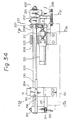
- the feed rod frame is mounted on the lower-mold die holder 110 by a pair of bearings 204 and 205. These bearings 204 and 205 are fixed by their lower portions to the die holder 110, as shown in Figs. 34 and 36, and support the supporting shaft 203 of the feed rod frame by the linear ball bearings 206 at their upper portions to be reciprocal in its axial direction.
- a driving rod 207 (see Fig. 37) is mounted on the supporting shaft 203 adjacent to the single-arm lever 202 by a pair of collar bearings 208 to be pivotal thereabout but not to be movable in the axial direction of the supporting shaft 203.
- a direct-mount type air cylinder 210 is mounted on the bearing 205 of the supporting shaft 203 (see Fig.
- a tension coil spring 213 is extended between the horizontal arm of the double-arm lever 201 of the feed rod frame and a bracket 212 fixed to the lower-mold die holder 110, so that the feed rod frame is always subjected to a force for the rotation about the supporting shaft 203 thereof in the direction indicated by arrow R1 (Fig. 38).
- a roller 214 is pivoted to the lower end of the vertical arm of the double-arm lever 201 and abuts against the front surface of a horizontal stopper rail 215 (see Figs.
- an insulating bushing 216 made of electrical insulator is studded in the stopper rail 215, and a screw-like contact terminal 217 formed of a conductor is screwed therein to extend to the roller abutting surface of the rail 215.
- a touch limit TL is fixed to the back surface of the bearing 204, and a terminal TLa thereof is connected to the terminal 217 through a lead wire (not shown).
- the roller 214 is formed of a conductor, and can be electrically connected to the touch limit TL through the lever 201, the supporting shaft 203, and the bearing 204.
- the supporting shaft 203 of the feed rod frame extends outwardly from the single-arm lever 202, and a sheet feed lever 220 is mounted on the extending portion of the feed rod frame by a pair of collar bearings 221 (see Fig. 33) to be pivotal but not to be movable in the axial direction of the supporting shaft 203.
- a bracket 222 is fixed near the distal end portion of the lever 220 to coincide with the IC sheet feed path T, and two sheet feed plates 223 are arranged on the upper surface of the bracket 222 to be parallel to each other.
- the sheet feed plates 223 are in frictional contact with the lower surface of an IC resin mold of the IC sheet S (Fig. 33) placed on the sheet feed portions of the guide rails 170.
- a tension coil spring 225 is extended between a bracket 224 fixed to the proximal end portion of the lever 220 and the lower-mold die holder 110, thereby applying to the lever 220 an upward force for the rotation in the direction indicated by arrow R3.
- a roller 227 is rotatably arranged on a bracket 226 fixed to the central portion of the lever 220, and abuts against the lower surfaces of the guide rails 170 to define a pivotal upper limit position of the lever 220.
- a roller 228 is rotatably arranged on the distal bent portion of the lever 220. The roller 228 is provided in correspondence with the lever 163 of the upper mold B20.
- the ejector B33 has an eject roller 230 and a pair of pressing roller 231, which are vertically aligned.
- the eject roller 230 has a structure shown in Fig.
- a sleeve 230b is mounted on a spindle 230a supported, through a cantilever bearing, by a bracket 232 fixed to the lower-mold die holder 110, a drum 230d is arranged on the sleeve 230b through two one-way clutches (shell-type roller clutches) 230c, a friction roller 230e and a guide flange 230f are respectively arranged at two end portions of the drum 230d, and a portion opposite to the spindle 230a is fixed by a pressing plate 230g and a screw 230h.
- shell-type roller clutches shell-type roller clutches
- the drum 230d When the spindle 230a is rotated at high speed by an electrical motor 233 with reduction gears, the drum 230d is rotated at high speed.
- the one-way clutches 230c allow the drum 230d to be rotated in a forward direction (in the IC sheet eject direction) but not to be rotated in the reverse direction.
- the pressing rollers 231 are rotatably mounted, via shafts 231a and bearings 231b, on the distal end portions of a pair of swing arms 235 mounted on a supporting shaft 234 which is supported by the bracket 232 in a cantilever manner. As shown in Fig.
- the pressing rollers 231 are urged against the friction rollers 230e of the eject roller 230 by a biasing force of a spring 236 fixed to the bracket 232.
- the lead frame F left after the IC punching operation is clamped between the friction rollers 230e and the pressing rollers 231 and is quickly ejected to a waste sheet chute B6 (Figs. 2 and 3).
- the IC sheet cutting operation by the IC sheet cutting press B described above is performed as follows.
- the IC sheet cutting press according to the present invention has the following advantages.
- the exchange operation of the press mold units in a short period of time allows a stop time of the press to be shortened, i.e., improves an operating efficiency, thus realizing a high producibility.
- the high producibility allows easy conversion of the cutting press for machining another type of IC sheet, thus keeping high compatibility of the press.
- the press mold unit since the press molds and the IC sheet feed mechanism are individually and detachably mounted on the die set, if only minimum number of necessary types of the press molds, the IC sheet feed mechanism, and the die set are prepared and they are combined appropriately, a desired press mold unit can be assembled. Therefore, a complete press mold unit need not be prepared for each type of IC sheet, resulting in great advantage in terms of manufacturing cost.
- the press mold unit performs the tie bar pinch forming operation before the punching operation during the IC sheet cutting process, the tie bar cutting operation during punching is made easier, so that a cutting burr of the tie bar will not be formed, and damage of IC packages can be prevented.
- a press force is applied to an IC to cut its tie bar F3 by a shearing force.
- the tie bar F3 has the same thickness as that of the lead frame and has a relatively large mechanical strength. Therefore, a considerably large press force is required.
- a burr may be formed on the cutting surface of the tie bar or an IC mold package may crack.
- the tie bar pinch forming press mold (DE4 an PH4) is arranged between the lead cut press mold (DE3 and PH3) and the punching press mold (DE5 and PH5), so that pinches are formed in tie bar cutting portions before the tie bar cutting operation by punching.
- Figs. 42 and 43 illustrate the main part of the punch PH4 for the tie bar pinch forming press mold.
- the punch PH4 has a pair of punched PU1 and PU2, and these punches are inserted in a central hole of th sheet pressing plate (stripper plate) 156, and are pivotally supported by pins 551 mounted on the plate 155.
- a cover plate 552 is fixed to the upper side of the central hole of the sheet pressing plate 155.
- a stop pin 553 arranged on the cover plate 552 restricts pivotal movement of the punches PU1 and PU2 during the pinch forming operation.
- a compression coil spring 554 is interposed between the punches PU1 and PU2 and the cover plate 552, so as not to move the punches PU1 and PU2 in the non-press state.
- reference numeral 157 denotes guide pins for mounting the plate 155 to the punch plate 151 or the intermediate plate 152 to be vertically movable.
- the die DE4 of the lower mold B10 facing the punch PH4 also has a pair of similar punches to those of the punch PH4.
- the tie bar F3 of the IC sheet S is pressed vertically by the distal end tips of the punches of the punch PH4 and the die DE4, thus forming a pinch PN, as shown in Fig. 44B.
- the pinch amount (pressed amount) of the pinch PN is defined by an adjusting plate 555 fixed to the lower surface of the plate 155.
- the tie bar F3 has a thickness of 0.43 mm
- the portion having such a thickness can be cut by a very small press force.
- the tie bar F3 can be easily cut by a small press force PF during the punching operation. Therefore, the cutting surface of the tie bar will not be burred or the resin mold package of the IC will be crack, thus improving the quality of IC's and manufacturing yield.
- the feed rod assembly is simply reciprocated along the IC sheet feed path, and the guide rails of the sheet guide assembly are moved vertically to engage or disengage the IC sheet with or from the feed pins. More specifically, since the IC sheet feed holes are simply moved with respect to the feed pins in their axial directions, engagement and disengagement therebetween can be smoothly performed. Therefore, an engagement error will rarely occur, and a highly reliable IC sheet feed operation can be realized. Smooth engagement or disengagement allows a high engagement precision between the feed holes and the feed pins. Therefore, the sheet feed operation can be performed with higher precision than in a conventional apparatus. Further, even if an engagement error occurs between the feed pins and the feed holes, the feed rod frame is moved upward, thus detecting the error by the touch limit.
- the guide rails of the sheet feed mechanism and the sheet feed lever are driven by downward movement of the upper mold and the action by the spring. Therefore, a special driving mechanism is not required, and complete synchronization with the press machining operation can be obtained.
- the sheet feed mechanism When an IC sheet is mounted on the press mold unit, in particular, the sheet feed mechanism, the bending of the IC sheet can be automatically removed, and the IC sheet can be maintained not to be bent during the IC sheet cutting operation, thus allowing a satisfactory IC sheet cutting operation.
- a waste sheet (lead frame) from which IC's are separated is clamped between the eject roller and the pressing rollers of the ejector to be quickly ejected. Therefore, even if the feed pins of the IC sheet feed mechanism are drifted from the feed holes of the waste sheet, waste sheet ejection can be reliably performed. Thus, the press operation can be prevented from being stopped due to waste sheet jam, thus realizing a smooth and efficient IC cutting operation.
- the IC sheet processing apparatus described above is constituted by combining the IC sheet cutting press B with other devices A, C, and D.
- the IC sheet cutting press can be independently used as a matter of course.
Description
- The present invention relates to an IC (Integrated Circuit) sheet cutting press for performing a series of press cutting operations while feeding an IC sheet stepwise in which IC sheet a plurality of IC's are coupled through a lead frame.
- An IC sheet cutting press of this type is known from the document US-A-3 722 060. The press described therein is provided for cutting IC sheets each comprising a plurality of ICs coupled through a lead frame, and includes an IC sheet feed mechanism for feeding the respective IC sheet stepwise, as well as a plurality of press molds for performing the series of the press cutting operations, wherein said sheet feed mechanism and said plurality of press molds are provided on a common die set to constitute a single mold unit.
- In said conventional IC sheet cutting press, for cutting different types of IC sheets, different types of completely composed mold units have to be provided. On the other hand, as it is well known, there are a large number of types of ICs and, hence, there are a large number of types of IC sheets. Therefore, for the conventional IS sheet cutting press, a correspondingly large number of single mold units are required causing the disadvantage of high cost.
- It is an object of the present invention to make availabilty of mold units for cutting different types of IC sheets more easy and less expensive.
- According to the present invention, this object is solved by providing an IC sheet cutting press having the features of claim 1.
- Further improvements are defined in the sub-claims.
- In an IC sheet cutting press of the present invention, a plurality of types of press molds for performing a series of press cutting machining and an IC sheet feed mechanism for feeding IC sheets stepwise are separately detachably mounted on a common die set to constitute a single press mold unit.
- The press mold unit performs a series of press cutting machining while IC sheets are fed stepwise, thus cutting IC's from a lead frame.
- When different types of IC sheets are to be machined, the press mold unit can be entirely exchanged with another press mold unit. Since the press molds and the IC sheet feed mechanism need not be positioned separately, replacement can be performed easily within a short period of time. In this case, if different press mold units have common fixing portions to a press table and coupling portions to a press ram, the exchange operation can be standardized and can be easily carried out by unskilled workers. As a result, the stop time of the IC cutting press can be shortened, thus minimizing reduction of the operation efficiency and realizing a high productivity. The IC sheet cutting press can be easily converted for machining another type of IC sheet, resulting in high compatibility.
- In the press mold unit of the present invention, the press molds and the IC sheet feed mechanism are detachably mounted on the die set and can be individually exchanged. Therefore, if a plurality of types of die sets, press molds, and IC sheet feed mechanisms are prepared and are selectively combined, various press mold units can be assembled. Therefore, different press units need not be prepared for each different type of IC sheet, resulting in a low mold manufacturing cost.
- In addition, when an apparatus for automatically loading IC sheets to the IC sheet cutting press, a press for bending lead terminals of separated IC's, and an apparatus for storing the IC's after the lead terminal bending process, are appropriately combined, an IC processing apparatus capable of automatically performing IC sheet processing including cutting of IC's from an IC sheet for a long period of time can be realized.
- The present invention will be described hereinafter in detail based on the preferred embodiments with reference to the accompanying drawings. Therein,
- Figures 1, 2, 3, and 4 are, respectively, a perspective view, a plan view, a front view, and a partially cutaway left-side view of an IC sheet processing apparatus;
- Figs. 5 to 8 show an IC sheet and IC sheet processing steps, in which:
- Fig. 5 is a plan view of an IC sheet;
- Fig. 6 is a plan view showing an IC sheet cutting process;
- Fig. 7 is a plan view of an IC cut from the IC sheet; and,
- Fig. 8 is a plan view of an IC after a lead terminal bending process;
- Figs. 23 to 43 show an IC sheet cutting press, in which:
- Fig. 23 is an exploded perspective view of a principal part of the press;
- Fig. 24 is a plan view of a lower mold with a sheet guide assembly mounted thereon;
- Figs. 25, 26, and 27 are, respectively, a partially sectional front view, a partially cutaway left-side view, and a partially sectional right-side view of a lower mold;
- Fig. 28 is a sectional view taken along a line F28 - F28 in Fig. 25;
- Figs. 29, 30, 31, and 32 are, respectively, a plan view, a partially sectional front view, a partially sectional left-side view, and a partially sectional right-side view of an upper mold;
- Fig. 33 is a plan view of a feed rod assembly and an ejector of an IC sheet feed mechanism;
- Figs. 34 and 35 are, respectively, a partially cutaway front view and a right-side view of the feed rod assembly;
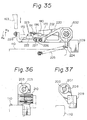
- Fig. 36 is a partially sectional side view taken along a line F36 - F36 in Fig. 34;
- Fig. 37 is a partially sectional side view taken along a line F37 - F37 in Fig. 34;
- Fig. 38 is a left-side view of the feed rod assembly;
- Fig. 39 is an enlarged sectional side view taken along a line F39 - F39 in Fig. 34;
- Fig. 40 is a front view of the ejector;
- Figs. 41A and 41B are exploded plan views of the ejector; and,
- Figs. 42 and 43 are, respectively, a partially sectional side view and a bottom view of a tie-bar pinch forming punch; and
- Figs. 44A, 44B, and 44C show a tie-bar pinch forming step and a punching step, and are sectional views taken along directions indicated by arrows F44A, F44B, and F44C in Fig. 6, respectively.
- Preferred embodiments of the present invention will be described with reference to an IC sheet processing apparatus which automatically performs cutting of IC's from an IC sheet and bending of lead terminals of the cut IC's for a long period of time.
- Figures 1 to 4 show an IC sheet processing apparatus, which basically comprises an IC sheet loader A, an IC sheet cutting press B, an IC sheet bending press C, and an IC unloader D.
- In the IC sheet loader A, a large number of magazines M each storing a large number of IC sheets S shown in Fig. 5 are stocked in a magazine stock section A1, and the IC sheets S are picked up from each magazine M one by one and fed to the IC sheet cutting press B by an IC sheet feeding section A2.
- The IC sheet cutting press B performs a series of press machining operations with respect to the IC sheet S to separate IC's therefrom, as shown in Fig. 6.
- The IC lead bending press C bends lead terminals L of the IC's separated from the IC sheet shown in Fig. 7, as shown in Fig. 8.
- The IC unloader D stores and stocks a large number of IC's after the lead bending process shown in Fig. 8 in a container CN.
- Note that reference symbol E in Figs. 2 and 4 denotes a dust collector for collecting a punched refuse or cutting dust produced during IC sheet cutting of the cutting press B.
- The arrangements and operations of the IC sheet S and the respective components A, B, C, and D of the IC sheet processing apparatus will be described separately.
- In the IC sheet S shown in Fig. 5, a plurality of DIP (Dual-Inline-Package) type IC's are coupled to each other through a lead frame F. The lead frame F is formed integrally with the lead terminals L, cross bars F1, dam bars F2, and tie bars F3. The dam bar F2 presents flowing of resin leaked from a mold during resin molding to the distal end portions of the lead terminals. The tie bar F3 directly couples the IC package to the lead frame F, and serves to hold the IC's until the last step of the IC sheet cutting process, as will be described later. A large number of holes having different shapes and sizes are formed in the lead frame F to be used for feeding the IC sheet or for position detection.
- The IC's are cut from the IC sheet S in such a manner that the IC sheet S is fed stepwise along an IC sheet feed path T at a distance equal to an arrangement interval p of the IC's (Fig. 5) to be subjected to a series of press machining steps, i.e., resin punching, dam bar cutting, lead cutting, tie bar pinch forming, and punching steps.
- (i) Resin punching step: Resins leaked to fill regions surrounded by the lead terminals L and the dam bar F2 (indicated by solid portions in Figs. 5 and 6) are punched.
- (ii) Dam bar cutting step: The dam bars F2 are removed.
- (iii) Lead cutting step: The frame cross bars F1 are removed to cut off the lead terminals L from the lead frame F. In an IC sheet wherein lead terminals L of adjacent IC's are coupled without being through the frame cross bar F1, the lead terminals are cut to be simply separated from each other. In the case of such an IC sheet, since the lead terminals L at the front and rear end portions of the IC sheet are already separated from the frame F, they need not be subjected to the lead cutting step. If performed, the distal end portions of the lead terminals may be burred, but preferably, the lead cutting step is not performed at the front and rear end portions of the IC sheet S.
- (iv) Tie bar pinch forming step: A pinch is formed in the tie bar F3 coupling the IC to the frame F. However, this step is not indispensable and can be omitted.
- (v) Punching step: The IC connected to the frame F through the tie bars F3 is punched from the frame F. In this case, when the tie bar pinch forming step is performed, the tie bar F3 can be cut by a small punching force, so that the tie bar F3 will not be burred or a resin mold can be prevented from being damaged.
- Note that the respective press machining steps are performed at an interval of 1.5p or 2p (p is an arrangement interval of IC's or a feed interval of an IC sheet), as shown in Fig. 6.
- The IC sheet loader A basically has a magazine stock section (to be referred to simply as a "stock section" hereinafter) A1 for storing the magazines M, the IC sheet feeding section A2 for picking up the IC sheets S one by one from a magazine MA located at an IC sheet pickup position TP on one end side of the stock section A1 and feeding it to the cutting press B, and a magazine returning section A3 for returning an empty magazine, from which the IC sheets S have been picked up, to the end position of the magazine array on the other end side of the stock section A1. Note that reference numeral A4 denotes an operation panel.
- The IC sheet cutting press B has a press mold unit B1, as shown in Fig. 23. The press mold unit B1 is mounted on a table B3 of a press frame, and is driven by a press ram B2 (Fig. 4) mounted in a ram housing B4.
- The press mold unit B1 comprises a lower mold B10, an upper mold B20, and an IC sheet feed mechanism B30, and performs a series of press machining operations to cut IC's from the IC sheet S (Fig. 5) by the upper and lower molds B10 and B20 while feeding the IC sheets S stepwise by the IC sheet feed mechanism B30. The arrangement and operation of the respective sections of the press mold unit B1 will be described hereinafter in detail.
- As shown in Figs. 24 to 27, the lower mold B10 is arranged in such a manner that respective dies DE1 to DE5 for press molds for performing above-mentioned series of press machining operations (i.e., resin punching, dam bar cutting, lead cutting, tie bar pinch forming, and punching) are detachably mounted on a single
common die holder 110. - Since the three dies DE1 to DE3 at the former stage have substantially the same mounting structure, the resin punching die DE1 at the first stage will be exemplified below. As shown in Fig. 24 or 25, the die DE1 is mounted on a
die plate 111. Thedie plate 111 is positioned by akey groove 113 in its bottom surface, aguide key 113 of the die holder 110 (Fig. 25), and a taperedmetal member 114 and afastening metal member 115 on one side of thedie plate 111, and is fixed to thedie holder 110 by abolt 116 at its opposite end portion. Note that thefastening metal member 115 is common to the die plates of the dies DE1 to DE3, as can be seen from Fig. 24. As shown in Figs. 24 to 27, a pair of dust-sealedguide bushings 117 are arranged on thedie plate 111, and are engaged with pilot pins 147 (to be described later; Figs. 30 and 32) of the upper mold B20. The two dies DE4 and DE5 at the latter stage are mounted on acommon die plate 118, as shown in Figs. 24 and 25. Thedie plate 118 is positioned by a key groove 119, a guide key 120 (Fig. 25), and a taperedmetal member 121 and a fastening metal member 122 (Figs. 24, 26, and 27) as in thedie plate 111, and is fixed to thedie holder 110 by a bolt. Thedie plate 118 has a pair of dust-sealed bushings 123 (Fig. 24) at its two end portions, which are engaged withpilot pins 158 of the upper mold B20 (to be described later; Figs. 30 and 31). As shown in Figs. 24 and 26, anair cylinder 124 and aguide rail 125 for feeding IC's cut from the IC sheet by the punching press mold (i.e., the die DE5 of the upper mold B10 and a punch PH5 of the upper mold B20) to the bending press C are arranged on thedie plate 118 to be perpendicular to the IC sheet feed path T. Since the tie bar pinch forming die DE4 and the punching die DE5 are always used in this combination, they are mounted on thecommon die plate 118, thus allowing easy mounting and removal of these dies. - The dies DE1 to DE5 are arranged along the IC sheet feed path T at given intervals, i.e., 1.5p or 2p shown in Fig. 6.
- As shown in Fig. 24, four
guide posts 130 are arranged on thedie holder 110, and when they are engaged withguide bushings 159 of the upper mold B20 (to be described later; Fig. 29), the upper mold B20 is mounted on the lower mold B10 to be vertically movable. As shown in Fig. 27, the lower end portion of eachguide post 130 is fitted in a hole of thedie plate 110 and is fixed by aflange 131, aretainer plate 132, and abolt 133. Stopper pins 135 are provided adjacent to the three guide posts 130. Thesepins 135 abut against stopper pins 160 (to be described later; Figs. 30 and 31) of the upper mold B20 to define the lower dead point of the upper mold B20. Other stopper pins 136 are arranged adjacent to the guide posts 130. Thesepins 136 abut against spring-biased stopper pins 161 (to be described later; Figs. 30 and 31) of the upper mold B20. - An air
joint block 137 for supplying a vacuum pressure for drawing an IC cut by the punching die DE5 and compressed air to theair cylinder 124 for feeding IC's is arranged on one side (the left side in Fig. 24) of thedie holder 110. Although a number of photosensors for detecting an IC sheet feed position are arranged on thedie holder 110, a detailed description thereof will be omitted. - Figures 24 to 27 illustrate a state wherein a sheet guide assembly B31 of the IC sheet feed mechanism B30 (Fig. 23) is mounted on the
die holder 110. The sheet guide assembly B31 will be described later. - The lower mold B10 is detachably mounted on the table B3 of the cutting press B. More specifically, as shown in Figs. 24, 25, and 27, a
key groove 138 is formed in the bottom surface of thedie holder 110, and a pair of taperedmetal members 139 are arranged on its one end side. As shown in Fig. 23, a guide key B3a and a fastening metal member B3b are fixed to the table B3 of the cutting press B to be perpendicular to each other. When thekey groove 138 of thedie holder 110 is engaged with the guide key B3a and the taperedmetal member 139 is engaged with the fastening metal member B3b, the lower mold B10 can be positioned, and is fixed, such that a bolt (not shown) is screwed in a tap hole B3c of the table B3 from a bolt hole 110a (in the upper left corner in Fig. 24) of thedie holder 110. Note that since the common fixing structure of the lower mold B10 with respect to the press table B3 is adopted, a compatibility with different press mold units B1 can be provided. - In Fig. 23, a hole B3d formed in the press table B3 is a dust collecting port corresponding to the dies DE1 to DE3 of the lower mold B10. The dust collecting port B3d communicates with a dust collector E through a hose or tube E1, as shown in Fig. 4, so that a punched refuse or cutting dust produced by the dies DE1 to DE3 is collected through the dust collecting port B3d.
- Note that the press B has a transparent safe cover B5. When the cover B5 is opened, not only the IC sheet cutting press B but also the entire IC sheet processing apparatus is automatically stopped.
- As shown in Figs. 29 to 32, the upper mold B20 is arranged so that punches PH1 to PH5 for the respective press molds for performing the above-mentioned series of press machining operations are detachably mounted on a single
common punch holder 140. - Since the punches PH1 to PH3 at the former stage have substantially the same mounting structure, the resin punch PH1 at the first stage will be exemplified below. As shown in Fig. 32, the punch PH1 is mounted on a
punch plate 141, which is detachably mounted on thepunch holder 140 by abolt 144 through anintermediate plate 142 and abase plate 143. A sheet pressing plate (or a stripper plate) 145 is mounted on thepunch plate 141 by a pair of spring-biased slide pins 146 to be vertically movable, and a pair of pilot pins 147 are fixed thereto. The pilot pins 147 are engaged with theguide bushings 117 of thedie holder 111 for the dies DE1 to DE3 of the lower mold B10 described above (Figs. 24 and 27). The punches PH4 and PH5 at the latter stage are mounted on apunch plate 151, as shown in Fig. 31, and thepunch plate 151 is detachably mounted on thepunch holder 140 by a bolt 154 (Fig. 29) through anintermediate plate 152 and abase plate 153. Thebase plate 153 is common to the punches PH4 and PH5, as shown in Fig. 30. This arrangement corresponds to that wherein thedie plate 118 commonly used for the dies DE4 and DE5 of the lower mold B10. A sheet pressing plate (or a stripper plate) 155 is mounted on thepunch plate 151 by a pair of spring-biased slide pins 156 and a pair of guide pins 157 to be vertically movable. A pair of pilot pins 158 are fixed to thecommon base plate 153, and are engaged with theguide bushings 123 of the lower mold B10 described above. - Four
guide bushings 159, threestopper pins 160, and four spring-biased stopper pins 161 are arranged on thepunch holder 140. As described above, theguide bushings 159 are engaged with the guide posts 130 of the lower mold B10, and the stopper pins 160 and 161 abut against the stopper pins 135 and 136 of the lower mold B10, respectively. - The
punch holder 140 has aram coupling member 162, which is engaged with the flange B2a (Figs. 30 and 32) at the distal end portion of the piston rod of the press ram B2 (Fig. 4) of the cutting press B. Thus, the upper mold B20 is vertically moved by the press ram B2, and a sheet cutting operation is performed by the dies DE1 to DE5 and the punches PH1 to PH5. - An L-shaped
lever 163 is fixed to one end portion of thepunch holder 140. Thelever 163 pushes down a sheet feed lever 220 (see Fig. 35) of the IC sheet feed mechanism B30 by utilizing downward movement of the upper mold B20, and will be described later. - Although the upper mold B10 also has a large number of photosensors for position detection during IC sheet feed, a detailed description thereof will be omitted.
- The IC sheet feed mechanism B30 comprises the sheet guide assembly B31 (illustrated in a stage wherein it is mounted on the lower mold B10), a feed rod assembly B32 for feeding the IC sheet along the sheet guide assembly, and an ejector B33 for ejecting a waste sheet after IC cutting, as shown in Fig. 23.
- The sheet guide assembly B31 has a pair of
guide rails 170 arranged on two sides of the IC sheet feed path T (Fig. 24), as shown in Figs. 24 to 28. Eachguide rail 170 has a supportingrail 171 having a rectangular section, and acover plate 172 fixed to the upper surface of therail 171 by a screw. The CI sheet S is fed, with the right and left side edges of the lead frame F (Fig. 5) engaged with the guide grooves between the supportingrails 171 and thecover plates 172. The end portions on one side of the supportingrails 171 of theguide rails 170 extend from the lower-mold die holder 110, and constitute a sheet feed portion on which the IC sheet fed by the IC sheet feeding section A2 of the IC sheet loader A is placed. As shown in Figs. 24, 25, and 28, guide blocks 173 are mounted on the extending end portions of the supportingrails 171, and the IC sheet S is inserted from the above between the guide blocks 173 to be placed on the supportingrails 171 by the lead frame side edge portion. Two sheet pressing plates 174 (only one is shown) are arranged on eachguide block 173. Thesheet pressing plates 174 normally extend inwardly, and when the IC sheet S is inserted from the above, they are extended outwardly to allow insertion of the IC sheet S. After insertion of the IC sheet, theplates 174 again extend inwardly to prevent the IC sheet S from being ejected outside. Note that the IC sheet S is often bent during its manufacture. However, thesheet pressing plates 174 suppress the bending of the IC sheet to hold it flat. The bending of the IC sheet is suppressed by the guide grooves of theguide rails 170 during the subsequent stepwise feed, thus allowing satisfactory press cutting. - As shown in Figs. 24 and 25, the
guide rails 170 are mounted on the lower-mold die holder 110 bylifters 180 at positions adjacent to their ends to be vertically movable. As shown particularly in the right portion of Fig. 25, eachlifter 180 has abody 181 fixed to thedie holder 110, and alift pin 182 is mounted in thebody 181 by a linear ball baring 183 to be vertically movable. The upper end portion of thelift pin 182 is inserted in the hole of the corresponding supportingrail 171 of theguide rail 170, and the lower end portion thereof is inserted in the hole of thedie holder 110, so that theguide rails 170 are biased upward by the action of acompression coil spring 184. Astopper plate 185 is fixed to the upper surface of thelifter body 181, and apawl 186 fixed to the lower surface of thecorresponding guide rail 170 is engaged with the lower surface of thestopper plate 185, thus defining the upper limit lift position (upper dead point) of theguide rail 170. As will be described later, theguide rails 170 are held at a level higher than that of the upper surface of the dies DE1 to DE5 in a non-press state wherein the upper mold B20 is located at its upper position. On the other hand, during the press process in which the upper mold B20 is moved downward, theguide rails 170 are pushed downward by the upper mold B20 to the level of the dies DE1 to DE5, thus performing IC sheet cutting. The lift operation of the guide rails 170 is associated with the IC sheet feed operation by the feed rod assembly B32. - Although not shown, a large number of sensor light transmission holes for detecting the IC sheet position are formed in the supporting
rails 171 and thecover plates 172 of theguide plates 170. A large number of elongated holes are formed in thecover plates 172 so as to allow engagement of feed pins 196 (Fig. 33) of the feed rod assembly B32 with the feed holds of the IC sheets. - As shown in Fig. 33, the feed rod assembly B32 has a
feed rod 190 extending parallel to the guide rails 170 (indicated by imaginary lines), and feedarms 191 to 195 are mounted on thefeed rod 190 to be perpendicular thereto. One or twofeed pins 196 extending downward are arranged on the lower surface of each feed arm. These feed pins 196 are engaged with the holes of the lead frame F of the IC sheet S (see Fig. 5) to perform the sheet feed operation. - The two end portions of the
feed rod 190 are respectively fixed so free end portions of a double-arm lever 201 and a single-arm lever 202. Theselevers shaft 203 but not movable in its axial direction. More specifically, thefeed rod 190, thelevers shaft 203 constitute a rectangular frame (to be referred to as "feed rod frame" hereinafter), in which thefeed rod 190 is swingable about the supportingshaft 203. - The feed rod frame is mounted on the lower-
mold die holder 110 by a pair ofbearings bearings die holder 110, as shown in Figs. 34 and 36, and support the supportingshaft 203 of the feed rod frame by thelinear ball bearings 206 at their upper portions to be reciprocal in its axial direction. A driving rod 207 (see Fig. 37) is mounted on the supportingshaft 203 adjacent to the single-arm lever 202 by a pair ofcollar bearings 208 to be pivotal thereabout but not to be movable in the axial direction of the supportingshaft 203. A direct-mounttype air cylinder 210 is mounted on the bearing 205 of the supporting shaft 203 (see Fig. 36), and its piston rod is coupled to one end of the drivingrod 207 through a floating joint 211. When theair cylinder 210 is operated, the feed rod frame is reciprocated in the directions indicated by arrows T1 and T2 along the IC sheet feed path T, as shown in Fig. 33. A stopper plate 209 (Figs. 33 and 37) is fixed to thebearing 205, so that the drivingrod 207 abuts against thestopper plate 209 so as to define a movement stroke p (shown in the right side portion in Fig. 34) of the feed rod frame. This movement stroke p corresponds to the IC sheet feed interval, as described later. - As clearly shown in Fig. 38, a
tension coil spring 213 is extended between the horizontal arm of the double-arm lever 201 of the feed rod frame and abracket 212 fixed to the lower-mold die holder 110, so that the feed rod frame is always subjected to a force for the rotation about the supportingshaft 203 thereof in the direction indicated by arrow R1 (Fig. 38). Aroller 214 is pivoted to the lower end of the vertical arm of the double-arm lever 201 and abuts against the front surface of a horizontal stopper rail 215 (see Figs. 33 and 34) fixed to the bearing 204 of the supportingshaft 203 so as to restrict the rotation of the feed rod frame in the direction indicated by arrow R1, thereby holding it in a normal horizontal position substantially as high as the level of the guide rails 170. When the feed rod frame is reciprocated in the directions indicated by arrows T1 and T2, theroller 214 is rotated, while abutting against with thestopper rail 215. - Further, as shown in Fig. 39, an insulating
bushing 216 made of electrical insulator is studded in thestopper rail 215, and a screw-like contact terminal 217 formed of a conductor is screwed therein to extend to the roller abutting surface of therail 215. A touch limit TL is fixed to the back surface of thebearing 204, and a terminal TLa thereof is connected to the terminal 217 through a lead wire (not shown). Theroller 214 is formed of a conductor, and can be electrically connected to the touch limit TL through thelever 201, the supportingshaft 203, and thebearing 204. Therefore, when theroller 214 is in contact with thecontact terminal 217, an electrically closed circuit is formed, thereby detecting that theroller 214 abuts against therail 215, that is, the feed rod frame is held at a normal horizontal position. As will be described later, if the feed pins 196 of thefeed rod 190 cannot be successfully inserted in the feed holes of the IC sheet and the feed rod frame is pushed up in the direction indicated by arrow R2, theroller 214 is released from therail 215, i.e., thecontact terminal 217 upon pivotal movement of the double-arm lever 201, and the electrical circuit is opened, thus detecting that the feed pins 196 and the feed holes of the IC sheet cannot be successfully engaged with each other. - As shown in Figs. 33 and 34, the supporting
shaft 203 of the feed rod frame extends outwardly from the single-arm lever 202, and asheet feed lever 220 is mounted on the extending portion of the feed rod frame by a pair of collar bearings 221 (see Fig. 33) to be pivotal but not to be movable in the axial direction of the supportingshaft 203. As shown in Figs. 33 and 35, abracket 222 is fixed near the distal end portion of thelever 220 to coincide with the IC sheet feed path T, and twosheet feed plates 223 are arranged on the upper surface of thebracket 222 to be parallel to each other. Thesheet feed plates 223 are in frictional contact with the lower surface of an IC resin mold of the IC sheet S (Fig. 33) placed on the sheet feed portions of the guide rails 170. When thelever 220 is moved in the direction indicated by arrow T1 together with the feed rod frame as will be described later, theplates 223 serve to feed the IC sheet S. - As shown in Fig. 35, a
tension coil spring 225 is extended between abracket 224 fixed to the proximal end portion of thelever 220 and the lower-mold die holder 110, thereby applying to thelever 220 an upward force for the rotation in the direction indicated by arrow R3. As shown in Figs. 33 and 35, aroller 227 is rotatably arranged on abracket 226 fixed to the central portion of thelever 220, and abuts against the lower surfaces of theguide rails 170 to define a pivotal upper limit position of thelever 220. Aroller 228 is rotatably arranged on the distal bent portion of thelever 220. Theroller 228 is provided in correspondence with thelever 163 of the upper mold B20. When theroller 228 is pushed downward by thelever 163 during downward movement of the upper mold B20, thelever 220 is pivoted in the direction indicated by arrow R4. Therollers rod 207 and theguide rails 170 and are rotated when thelever 220 is moved in the directions indicated by arrows T1 and T2 together with the feed rod frame. - The operation of the sheet guide assembly B31 and the feed rod assembly B32 is now described.
- (i) First, the feed rod frame of the feed rod assembly B32 and the
sheet feed lever 220 are located at positions to which they are driven by theair cylinder 210 in the direction indicated by arrow T2 (i.e., the positions shown in Figs. 33 and 34). In this state, when the upper mold B20 is held in its upper position (i.e., non-press position), theguide rails 170 of the sheet guide assembly B31 are lifted by thelifters 180 to a level as high as that of thefeed rod 190, and the feed pins 196 of thefeed arms 191 to 195 are engaged with the corresponding feed holes of the IC sheet S. Meanwhile, thesheet feed lever 220 of the feed rod assembly B32 is also pivoted to its upper position, and the sheet feed plates thereof are brought into frictional contact with the IC's of the IC sheet S placed on the sheet feed portions of the guide rails 170. - (ii) Next, the
feed rod 190 and thefeed lever 220 are driven by theair cylinder 210 in the direction indicated by arrow T1, and the IC sheet is fed by one interval p in the same direction. - (iii) After the IC sheet feed operation, the upper mold B20 is moved downward, thus performing a press machining operation. At this time, upon downward movement of the upper mold B20, the
guide rails 170 are pushed downward, and the IC sheet S is released from the feed pins 196 of thefeed rod 190. At the same time, thesheet feed lever 220 is pivoted downward, and the ICsheet feed plates 223 are released from the IC's. In this state, theair cylinder 210 is operated in the reverse direction, and thefeed rod 190 and thefeed lever 220 are driven in the direction indicated by arrow T2. - (iv) Thereafter, the upper mold B20 is moved upward to the non-press position, and upon this movement, the
guide rails 170 and thefeed lever 220 are also moved upward, so that the feed pins 196 are engaged with the feed holes of the IC sheet and thesheet feed plates 223 are in contact with the IC's, thus performing the next sheet feed operation. - In the above operation (iv), if the feed pins 196 cannot be successfully engaged with the feed holes of the IC sheet for any unprospected cause, the
feed rod 190 is pushed upward about the supporting shaft 203 (in the direction indicated by arrow R2 in Fig. 38), and theroller 214 is released from thestopper rail 215. This state is then detected by the touch limit TL. Thus, not only the IC sheet cutting press B but also the entire IC sheet processing apparatus is stopped. - As shown in Figs. 40, 41A, and 41B, the ejector B33 has an
eject roller 230 and a pair ofpressing roller 231, which are vertically aligned. Theeject roller 230 has a structure shown in Fig. 41B, wherein a sleeve 230b is mounted on aspindle 230a supported, through a cantilever bearing, by abracket 232 fixed to the lower-mold die holder 110, adrum 230d is arranged on the sleeve 230b through two one-way clutches (shell-type roller clutches) 230c, afriction roller 230e and aguide flange 230f are respectively arranged at two end portions of thedrum 230d, and a portion opposite to thespindle 230a is fixed by apressing plate 230g and ascrew 230h. When thespindle 230a is rotated at high speed by anelectrical motor 233 with reduction gears, thedrum 230d is rotated at high speed. Note that the one-way clutches 230c allow thedrum 230d to be rotated in a forward direction (in the IC sheet eject direction) but not to be rotated in the reverse direction. Thepressing rollers 231 are rotatably mounted, viashafts 231a andbearings 231b, on the distal end portions of a pair ofswing arms 235 mounted on a supportingshaft 234 which is supported by thebracket 232 in a cantilever manner. As shown in Fig. 40, thepressing rollers 231 are urged against thefriction rollers 230e of theeject roller 230 by a biasing force of aspring 236 fixed to thebracket 232. Thus, the lead frame F (waste sheet) left after the IC punching operation is clamped between thefriction rollers 230e and thepressing rollers 231 and is quickly ejected to a waste sheet chute B6 (Figs. 2 and 3). - The IC sheet cutting operation by the IC sheet cutting press B described above is performed as follows.
- (i) The press mold unit B1 is assembled into a unit, after the lower mold B10, the upper mold B20, and the IC sheet feed mechanism B30 are individually adjusted and preassembled in correspondence with IC sheets to be cut. Then, the press mold unit B1 is mounted on the press table B3. Upon mounting, the upper mold B20 is automatically coupled to the press ram B2. Then, the air
joint block 137 is connected to air lines and vacuum pressure lines, and the electric wirings for the photosensors are connected to a connector (not shown), whereby the ready for operation is completed. First, the upper mold B20 is located at its upper position, i.e., the non-press position, and the feed rod frame (190, 201, 202, and 203) of the feed rod assembly B32 of the sheet feed mechanism B20 and thesheet feed lever 220 are located at positions to which they have been driven in the direction indicated by arrow T2 (note that the driving operation of the feed rod frame and the sheet feed lever will be referred to simply as "the driving operation of the feed rod assembly B32" hereinafter). - (ii) In operation, first, one IC sheet S is fed to the sheet feed position of the
guide rails 170 of the IC sheet feed mechanism B30 by the IC sheet feeding section A2 from the IC sheet loader A. At this time, as described above, the IC sheet S is prevented by thesheet pressing plates 174 from being undesirably ejected outside and its bending is removed thereby. - (iii) After the IC sheet is fed, the
air cylinder 210 of the IC sheet feed mechanism B30 is operated, and the feed rod assembly B32 is driven in the direction indicated by arrow T1, so that the IC sheet S on the sheet feed portion is fed by one interval by thefeed lever 220. Then, the upper mold B20 is moved downward by the press ram B2, so that theguide rails 170 and thesheet feed lever 220 are pushed downward. In this state, the feed rod assembly B32 is driven by theair cylinder 210 in the direction indicated by arrow T2 to its initial position. Thereafter, the upper mold B20 is moved upward, and theguide rails 170 and thefeed lever 220 are moved upward. In the illustrated embodiment, the sheet feed portion of the guide rails 170 is apart by 2p from a position at which the feed pins 196 of thefeed rod 190 are first engaged with the feed holes of the IC sheet S. Therefore, the feed operation by thefeed lever 220 is performed twice. - (iv) After the two feed operations, the
pins 196 of thefirst feed arm 191 are engaged with the feed holes of the IC sheet. In this state, the feed rod assembly B32 is driven in the direction indicated by arrow T1, and the IC sheet S is fed by thefeed rod 190. After completion of the feed operation, the upper mold B20 is moved downward, and upon this downward movement, theguide rails 170 are moved downward, thus releasing the IC sheet S from the feed pins 196. In this state, the feed rod assembly B32 is driven in the direction indicated by arrow T2 to its initial position. Thereafter, when the upper mold B20 is moved upward, theguide rails 170 are also moved upward, and the next feed holes of the IC sheet S are engaged with the feed pins 196, thus performing the next feed operation. As the IC sheet is fed stepwise, the feed pins 196 of thefeed arms 192 to 195 perform the stepwise feed operation. In the illustrated embodiment, the feed start position by thefeed rod 190 is apart by 2p from the resin punching position. Therefore, two more feed operations (four times from the sheet feed portion) are performed until the leading IC of the IC sheet S is fed to the resin punching position. - (v) When the leading IC has reached the resin punching position, the leaked resin is punched by the die DE1 and the punch PH1 during the press process of the upper mold B20, as shown in Fig. 6. Thereafter, each time the IC sheet is fed by 2p, 1p, 2p, and 2p, the dam bar cutting, lead cutting, tie bar pinch forming, and punching operations are performed by the dies DE2 to DE5 and the punches PH2 to PH5, thus separating the IC from the lead frame F. The separated IC is drawn by vacuum suction in the die DE5, is pushed onto the
guide rail 125 by theair cylinder 124, and is then fed to the bending press C. - (vi) In this manner, the IC sheet S is progressively fed and cut, and when its trailing end is send out of the sheet feed portion of the
guide rails 170, the next IC sheet is fed from the IC sheet loader. Then, this IC sheet is subjected to the IC cutting operation while being similarly fed stepwise. - (vii) The waste sheet (lead frame F) after all the IC's are separated is quickly ejected to the waste sheet chute B6 immediately after the last IC is separated (i.e., before the upper mold B20 is moved upward and the feed holes of the lead frame F are engaged with the feed pins 196).
- During the IC cutting operation described above, confirmation of the IC sheet feed operation to the IC sheet feed portion (i.e., the presence/absence of the IC sheet), detection of the IC sheet feed position along the guide rails, the feed operation of the separated IC's to the bending press, and ejection of the waste sheet are performed by photosensors. Although these photosensors and various other sensors are not shown, almost all of them are installed in the press mold unit B1, and others which can be arranged at predetermined positions regardless of the types of IC sheet, i.e., the types of press mold unit are arranged on the table B3 of the press B or other portions.
- The IC sheet cutting press according to the present invention has the following advantages.
- Since a plurality of types of press molds (dies and punches) for performing a series of press machining operations and the IC sheet feed mechanism for feeding the IC sheet are integrated as a unit, when the press is converted for machining another type of IC sheet, the entire press mold unit can be exchanged with another unit. Therefore, various complex adjustments, e.g., alignment between respective press molds and alteration of sheet feed interval, can be omitted, and conversion can be easily performed in a very short period of time. In particular, as in the above embodiment, when different press mold units adopt a common structure for the fixing to the press table and the coupling with the press ram, and exchange operation of press mold units can be standardized, and can be easily performed by an unskilled operator.
- The exchange operation of the press mold units in a short period of time allows a stop time of the press to be shortened, i.e., improves an operating efficiency, thus realizing a high producibility.
- The high producibility allows easy conversion of the cutting press for machining another type of IC sheet, thus keeping high compatibility of the press.
- In the press mold unit, since the press molds and the IC sheet feed mechanism are individually and detachably mounted on the die set, if only minimum number of necessary types of the press molds, the IC sheet feed mechanism, and the die set are prepared and they are combined appropriately, a desired press mold unit can be assembled. Therefore, a complete press mold unit need not be prepared for each type of IC sheet, resulting in great advantage in terms of manufacturing cost.
- Note that detailed arrangements of the lower mold, the upper mold, and the IC sheet feed mechanism of the press mold unit are not limited to those shown in the drawings, and various modifications may be made. However, the embodiment shown in the drawings further has the following advantages.
- Since the press mold unit performs the tie bar pinch forming operation before the punching operation during the IC sheet cutting process, the tie bar cutting operation during punching is made easier, so that a cutting burr of the tie bar will not be formed, and damage of IC packages can be prevented.
- This aspect is now described below in detail.
- As shown in Figs. 44A, 44B, and 44C, during the punching operation, a press force is applied to an IC to cut its tie bar F3 by a shearing force. However, the tie bar F3 has the same thickness as that of the lead frame and has a relatively large mechanical strength. Therefore, a considerably large press force is required. In addition, a burr may be formed on the cutting surface of the tie bar or an IC mold package may crack.
- In the above embodiment of the present invention, the tie bar pinch forming press mold (DE4 an PH4) is arranged between the lead cut press mold (DE3 and PH3) and the punching press mold (DE5 and PH5), so that pinches are formed in tie bar cutting portions before the tie bar cutting operation by punching.
- Figs. 42 and 43 illustrate the main part of the punch PH4 for the tie bar pinch forming press mold. The punch PH4 has a pair of punched PU1 and PU2, and these punches are inserted in a central hole of th sheet pressing plate (stripper plate) 156, and are pivotally supported by
pins 551 mounted on theplate 155. Acover plate 552 is fixed to the upper side of the central hole of thesheet pressing plate 155. Astop pin 553 arranged on thecover plate 552 restricts pivotal movement of the punches PU1 and PU2 during the pinch forming operation. Acompression coil spring 554 is interposed between the punches PU1 and PU2 and thecover plate 552, so as not to move the punches PU1 and PU2 in the non-press state. Note thatreference numeral 157 denotes guide pins for mounting theplate 155 to thepunch plate 151 or theintermediate plate 152 to be vertically movable. - Although not shown, the die DE4 of the lower mold B10 facing the punch PH4 also has a pair of similar punches to those of the punch PH4. When the upper mold B20 performs the press operation, the tie bar F3 of the IC sheet S is pressed vertically by the distal end tips of the punches of the punch PH4 and the die DE4, thus forming a pinch PN, as shown in Fig. 44B. The pinch amount (pressed amount) of the pinch PN is defined by an adjusting
plate 555 fixed to the lower surface of theplate 155. For example, if the tie bar F3 has a thickness of 0.43 mm, the distal end tips of the punches PU1 and PU2 of the punch PH4 are set to be offset from the lower surface of the adjustingplate 555 by 0.18 mm, and the same setting operation is performed for the die DE4. Then, the tie bar F3 is pressed from the both sides by 0.18 mm, so that the portion formed with the pinch PN has a thickness of 0.43 - (0.18 x 2) = 0.07 mm. The portion having such a thickness can be cut by a very small press force. - As shown in Fig. 44C, the tie bar F3 can be easily cut by a small press force PF during the punching operation. Therefore, the cutting surface of the tie bar will not be burred or the resin mold package of the IC will be crack, thus improving the quality of IC's and manufacturing yield.
- As for the sheet feed mechanism, the feed rod assembly is simply reciprocated along the IC sheet feed path, and the guide rails of the sheet guide assembly are moved vertically to engage or disengage the IC sheet with or from the feed pins. More specifically, since the IC sheet feed holes are simply moved with respect to the feed pins in their axial directions, engagement and disengagement therebetween can be smoothly performed. Therefore, an engagement error will rarely occur, and a highly reliable IC sheet feed operation can be realized. Smooth engagement or disengagement allows a high engagement precision between the feed holes and the feed pins. Therefore, the sheet feed operation can be performed with higher precision than in a conventional apparatus. Further, even if an engagement error occurs between the feed pins and the feed holes, the feed rod frame is moved upward, thus detecting the error by the touch limit.
- The guide rails of the sheet feed mechanism and the sheet feed lever are driven by downward movement of the upper mold and the action by the spring. Therefore, a special driving mechanism is not required, and complete synchronization with the press machining operation can be obtained.
- When an IC sheet is mounted on the press mold unit, in particular, the sheet feed mechanism, the bending of the IC sheet can be automatically removed, and the IC sheet can be maintained not to be bent during the IC sheet cutting operation, thus allowing a satisfactory IC sheet cutting operation.
- A waste sheet (lead frame) from which IC's are separated is clamped between the eject roller and the pressing rollers of the ejector to be quickly ejected. Therefore, even if the feed pins of the IC sheet feed mechanism are drifted from the feed holes of the waste sheet, waste sheet ejection can be reliably performed. Thus, the press operation can be prevented from being stopped due to waste sheet jam, thus realizing a smooth and efficient IC cutting operation.
- Note that the IC sheet processing apparatus described above is constituted by combining the IC sheet cutting press B with other devices A, C, and D. However, the IC sheet cutting press can be independently used as a matter of course.
Claims (5)
- An IC sheet cutting press (B) for performing a series of press cutting operations while feeding an IC sheet (S) stepwise in which sheet a plurality of IC's are coupled through a lead frame (F), wherein each of a plurality of types of press molds (DE1 to DE5, PH1 to PH5) for performing the series of the press cutting operations and an IC sheet feed mechanism (B30) for feeding the IC sheet stepwise are separately and detachably mounted on a common die set (110, 140) to constitute a single press mold unit (B1) being adapted to be assembled into an adjusted condition in correspondence with the IC sheet to be cut prior to mounting on a press table (B3) of a press frame.
- The IC sheet cutting press as claimed in claim 1, wherein said press mold unit (B1) comprises a lower mold (B10) in which dies of said press molds are separately and detachably mounted on a single common die holder and which is detachably fixed to said press table (B3), and upper mold (B20) in which punches of said press molds are separately and detachably mounted on a single common punch holder and which is disengageably coupled to a press ram (B2) of said cutting press, and said IC sheet feed mechanism (B30) is detachably mounted on said lower mold (B10).
- The IC sheet cutting press as claimed in claim 2, wherein a portion of said lower mold (B10) fixed to said press table (B3) and a portion of said upper mold (B20) coupled to said press ram (B2) are common to different types of press mold units (B1).
- The IC sheet cutting press as claimed in anyone of the preceding claims, wherein said IC sheet feed mechanism (B30) comprises a waste sheet ejector (B33) for ejecting a waste sheet from which IC's have separated, said waste sheet ejector comprising:(a) an eject roller (230) in contact with one surface of the waste sheet;(b) a pressing roller (231) which is in contact with the other surface of the waste sheet to urge the waste sheet against the eject roller (230); and(c) a motor (233) for rotating said eject roller (230) at high speed.
- The IC sheet cutting press as claimed in anyone of the preceding claims, for cutting IC sheets (S) comprising a plurality of IC's coupled through said lead frame (F) in which at least terminals (L) and tie bars (F3) are formed, wherein said plurality of press molds (DE1 to DE5, PH1 to PH5) includes at least a press mold for finally cutting the tie bars (F3) by punching to separate IC's from said lead frame (F) and a press mold arranged before tee tie bar cutting press mold for forming pinches to correspondingly cutting portions of the tie bars (F3).
Applications Claiming Priority (18)
| Application Number | Priority Date | Filing Date | Title |
|---|---|---|---|
| JP60252645A JPS62116435A (en) | 1985-11-13 | 1985-11-13 | Ic sheet supply/exhaust device |
| JP60252644A JPS62116434A (en) | 1985-11-13 | 1985-11-13 | Ic sheet supply/exhaust device |
| JP252645/85 | 1985-11-13 | ||
| JP252644/85 | 1985-11-13 | ||
| JP253815/85 | 1985-11-14 | ||
| JP60253815A JPS62114732A (en) | 1985-11-14 | 1985-11-14 | Ic cutting press |
| JP182/86 | 1986-01-07 | ||
| JP61000182A JPS62158350A (en) | 1986-01-07 | 1986-01-07 | Cutting method for ic |
| JP61007944A JPS62168621A (en) | 1986-01-20 | 1986-01-20 | Cutting press for ic |
| JP7945/86 | 1986-01-20 | ||
| JP794586A JPS62168620A (en) | 1986-01-20 | 1986-01-20 | Ic cutting press |
| JP794786A JPS62166550A (en) | 1986-01-20 | 1986-01-20 | Ic lead bending press |
| JP7944/86 | 1986-01-20 | ||
| JP7949/86 | 1986-01-20 | ||
| JP7947/86 | 1986-01-20 | ||
| JP794986A JPS62166551A (en) | 1986-01-20 | 1986-01-20 | Ic lead bending press |
| JP61058210A JPS62235104A (en) | 1986-03-18 | 1986-03-18 | Ic housing device |
| JP58210/86 | 1986-03-18 |
Publications (3)
| Publication Number | Publication Date |
|---|---|
| EP0222401A2 EP0222401A2 (en) | 1987-05-20 |
| EP0222401A3 EP0222401A3 (en) | 1990-09-05 |
| EP0222401B1 true EP0222401B1 (en) | 1994-02-16 |
Family
ID=27576398
Family Applications (1)
| Application Number | Title | Priority Date | Filing Date |
|---|---|---|---|
| EP19860115753 Expired - Lifetime EP0222401B1 (en) | 1985-11-13 | 1986-11-13 | IC sheet cutting press |
Country Status (3)
| Country | Link |
|---|---|
| US (1) | US4972572A (en) |
| EP (1) | EP0222401B1 (en) |
| KR (1) | KR910001118B1 (en) |
Families Citing this family (21)
| Publication number | Priority date | Publication date | Assignee | Title |
|---|---|---|---|---|
| DE8901638U1 (en) * | 1989-01-31 | 1989-06-22 | Frost, Guenther, 8400 Regensburg, De | |
| JP2596217Y2 (en) * | 1991-06-21 | 1999-06-07 | 山形日本電気株式会社 | Cutting molding equipment |
| JPH07148535A (en) * | 1993-11-30 | 1995-06-13 | Apic Yamada Kk | Suction transferring die |
| JP3542365B2 (en) * | 1993-11-30 | 2004-07-14 | アピックヤマダ株式会社 | General-purpose lead processing machine |
| WO1999003128A2 (en) * | 1997-07-09 | 1999-01-21 | Systemation Engineered Products, Inc. | Singulation system for chip-scale packages |
| SG82620A1 (en) * | 1998-07-17 | 2001-08-21 | Towa Corp | Method and apparatus for processing resin sealed lead frame |
| JP3741995B2 (en) * | 2001-10-31 | 2006-02-01 | 株式会社ルネサステクノロジ | Device and method for removing tie bar after resin sealing of semiconductor device, and method for manufacturing semiconductor device |
| EP1321965A1 (en) * | 2001-12-07 | 2003-06-25 | O.LA.ME.F. di FAUSONE RENZO e C. S.n.c. | Apparatus for performing of transistors |
| CN102328004B (en) * | 2011-10-12 | 2013-04-24 | 西安建筑科技大学 | Bending machine for small-diameter wires |
| JP2015184162A (en) * | 2014-03-25 | 2015-10-22 | セイコーエプソン株式会社 | Electronic component conveyance device and electronic component inspection device |
| CN105035709A (en) * | 2015-08-05 | 2015-11-11 | 海宁联丰磁业股份有限公司 | Multifunctional blanking device for magnetic cores |
| CN105965684A (en) * | 2016-04-18 | 2016-09-28 | 重庆卓工科技有限公司 | Green brick auxiliary pushing mechanism |
| CN107826712B (en) * | 2017-11-01 | 2020-04-10 | 池杭杭 | Cutting-off and blanking finishing device for integrated circuit element packaging tube |
| CN108847397B (en) * | 2018-04-20 | 2020-05-05 | 四川旭茂微科技有限公司 | Rectifier bridge pin bending device and using method thereof |
| CN110211901B (en) * | 2019-06-11 | 2021-07-13 | 凌顶世纪科技成都有限公司 | Novel full-automatic forming machine |
| CN110369608A (en) * | 2019-06-28 | 2019-10-25 | 无锡红光微电子股份有限公司 | The Trim Molding device of semiconductor devices |
| CN111070294B (en) * | 2019-12-25 | 2021-04-20 | 芜湖恒丰彩印包装股份有限公司 | Safety protection mechanism of automatic die cutting machine |
| CN111646162B (en) * | 2020-05-09 | 2021-06-04 | 温岭市光明电器有限公司 | Steel sheet orientation mechanism for steel sheet adhesion and iron core assembly machine of direct current motor |
| CN111842681B (en) * | 2020-07-09 | 2022-07-22 | 瑞茂金泰(山东)智能设备制造有限责任公司 | Steel plate pressing ring feeding device |
| CN112193810B (en) * | 2020-12-09 | 2021-03-23 | 爱汽科技(佛山)有限公司 | Automatic bar conveying device and gear production line using same |
| CN112547978A (en) * | 2020-12-29 | 2021-03-26 | 福建汇达建筑工程有限公司 | Steel bar bending machine for building engineering |
Family Cites Families (11)
| Publication number | Priority date | Publication date | Assignee | Title |
|---|---|---|---|---|
| US764851A (en) * | 1902-02-21 | 1904-07-12 | Crompton & Knowles Loom Works | Automatic feed mechanism. |
| US3469754A (en) * | 1966-06-07 | 1969-09-30 | Litton Business Systems Inc | Tag feed device |
| FR1488830A (en) * | 1966-08-08 | 1967-07-13 | Nat Dairy Prod Corp | Method and apparatus for forming blanks |
| US3745808A (en) * | 1969-06-18 | 1973-07-17 | Y Hosaka | Die set having automatic feed between successive stages |
| US3650232A (en) * | 1970-09-08 | 1972-03-21 | Amp Inc | Method and apparatus for manufacturing lead frames |
| US3722060A (en) | 1971-07-27 | 1973-03-27 | F Gaiser | Machine |
| US3866471A (en) * | 1973-12-03 | 1975-02-18 | Kaller Die & Tool Company | Progressive die |
| US4064917A (en) * | 1976-10-18 | 1977-12-27 | Honeywell Information Systems Inc. | Apparatus for cutting and forming flexible beam leads of an integrated circuit chip |
| FR2379909A1 (en) * | 1977-02-04 | 1978-09-01 | Cii Honeywell Bull | METHOD AND APPARATUS FOR MOUNTING DEVICES ON A SUBSTRATE |
| US4099322A (en) * | 1977-02-07 | 1978-07-11 | Littelfuse, Inc. | Method for making plug-in fuse assemblies |
| US4619028A (en) * | 1983-03-25 | 1986-10-28 | L H Carbide Corporation | Apparatus for manufacture of laminated parts |
-
1986
- 1986-11-13 EP EP19860115753 patent/EP0222401B1/en not_active Expired - Lifetime
- 1986-11-13 US US06/929,781 patent/US4972572A/en not_active Expired - Fee Related
- 1986-11-13 KR KR1019860009593A patent/KR910001118B1/en not_active IP Right Cessation
Also Published As
| Publication number | Publication date |
|---|---|
| KR910001118B1 (en) | 1991-02-23 |
| EP0222401A3 (en) | 1990-09-05 |
| KR870005451A (en) | 1987-06-09 |
| US4972572A (en) | 1990-11-27 |
| EP0222401A2 (en) | 1987-05-20 |
Similar Documents
| Publication | Publication Date | Title |
|---|---|---|
| EP0222401B1 (en) | IC sheet cutting press | |
| CN113878021A (en) | Automatic production equipment with functions of metal plate punching and in-mold riveting | |
| CN113857415B (en) | Rivet loading device of automatic current starter assembly machine | |
| CN112845963B (en) | Element shaping and cutting device | |
| CN213503301U (en) | Full-automatic electric core labeling device | |
| CN111672974B (en) | Precision punching machine | |
| CN115383441B (en) | Press mounting equipment for shift fork shaft assembly of gearbox | |
| CN210476082U (en) | High-speed 90-degree rotary material taking and assembling manipulator | |
| CN211248010U (en) | Automatic steel ball riveting equipment | |
| CN210358642U (en) | Automatic metal plate bending equipment | |
| CN109650109B (en) | Paper sheet conveying device | |
| JPS62114732A (en) | Ic cutting press | |
| JP2001076835A (en) | Terminal mounting machine for pressure-contact connector | |
| CN220196808U (en) | Photovoltaic terminal box lead wire processing terminal box installation all-in-one | |
| CN219151389U (en) | Multi-linkage mechanical arm processing equipment | |
| CN219188221U (en) | Automatic bending equipment | |
| CN111064064A (en) | Automatic 5G terminal machining system and working method thereof | |
| CN215967346U (en) | Terminal feed mechanism | |
| CN111564744B (en) | Communication connector assembling equipment for connector assembling tester | |
| CN217595628U (en) | Side punching die convenient for feeding | |
| CN220156958U (en) | Tubular material feeding device | |
| CN109786150A (en) | A kind of telephone's faceplate key assembling device and assembly equipment and method | |
| CN216178275U (en) | Automatic splicing mechanism and automatic installation all-in-one machine of low-voltage circuit breaker | |
| CN219585082U (en) | Magnetic core forming machine with automatic feeding function | |
| CN220127410U (en) | High-speed in-mold riveting contact relay terminal mold |
Legal Events
| Date | Code | Title | Description |
|---|---|---|---|
| PUAI | Public reference made under article 153(3) epc to a published international application that has entered the european phase |
Free format text: ORIGINAL CODE: 0009012 |
|
| AK | Designated contracting states |
Kind code of ref document: A2 Designated state(s): DE FR GB |
|
| PUAL | Search report despatched |
Free format text: ORIGINAL CODE: 0009013 |
|
| AK | Designated contracting states |
Kind code of ref document: A3 Designated state(s): DE FR GB |
|
| 17P | Request for examination filed |
Effective date: 19910304 |
|
| 17Q | First examination report despatched |
Effective date: 19911113 |
|
| RBV | Designated contracting states (corrected) |
Designated state(s): GB |
|
| GRAA | (expected) grant |
Free format text: ORIGINAL CODE: 0009210 |
|
| REG | Reference to a national code |
Ref country code: DE Ref legal event code: 8566 |
|
| AK | Designated contracting states |
Kind code of ref document: B1 Designated state(s): GB |
|
| PLBE | No opposition filed within time limit |
Free format text: ORIGINAL CODE: 0009261 |
|
| STAA | Information on the status of an ep patent application or granted ep patent |
Free format text: STATUS: NO OPPOSITION FILED WITHIN TIME LIMIT |
|
| 26N | No opposition filed | ||
| PGFP | Annual fee paid to national office [announced via postgrant information from national office to epo] |
Ref country code: GB Payment date: 19981113 Year of fee payment: 13 |
|
| PG25 | Lapsed in a contracting state [announced via postgrant information from national office to epo] |
Ref country code: GB Free format text: LAPSE BECAUSE OF NON-PAYMENT OF DUE FEES Effective date: 19991113 |
|
| GBPC | Gb: european patent ceased through non-payment of renewal fee |
Effective date: 19991113 |