EP0221762B1 - Transport for tape cartridge with leader block - Google Patents
Transport for tape cartridge with leader block Download PDFInfo
- Publication number
- EP0221762B1 EP0221762B1 EP86308401A EP86308401A EP0221762B1 EP 0221762 B1 EP0221762 B1 EP 0221762B1 EP 86308401 A EP86308401 A EP 86308401A EP 86308401 A EP86308401 A EP 86308401A EP 0221762 B1 EP0221762 B1 EP 0221762B1
- Authority
- EP
- European Patent Office
- Prior art keywords
- tape
- cartridge
- leader block
- transport
- take
- Prior art date
- Legal status (The legal status is an assumption and is not a legal conclusion. Google has not performed a legal analysis and makes no representation as to the accuracy of the status listed.)
- Expired - Lifetime
Links
- 230000032258 transport Effects 0.000 description 46
- 230000007246 mechanism Effects 0.000 description 20
- 238000003780 insertion Methods 0.000 description 8
- 230000037431 insertion Effects 0.000 description 8
- 239000002184 metal Substances 0.000 description 6
- 238000013500 data storage Methods 0.000 description 4
- 238000000605 extraction Methods 0.000 description 3
- 230000009471 action Effects 0.000 description 2
- 238000013497 data interchange Methods 0.000 description 2
- 238000000034 method Methods 0.000 description 2
- 230000002093 peripheral effect Effects 0.000 description 2
- 229920004943 Delrin® Polymers 0.000 description 1
- 230000001133 acceleration Effects 0.000 description 1
- 239000011888 foil Substances 0.000 description 1
- 239000000463 material Substances 0.000 description 1
- 230000008569 process Effects 0.000 description 1
- 125000006850 spacer group Chemical group 0.000 description 1
- 230000007723 transport mechanism Effects 0.000 description 1
Images


Classifications
-
- G—PHYSICS
- G11—INFORMATION STORAGE
- G11B—INFORMATION STORAGE BASED ON RELATIVE MOVEMENT BETWEEN RECORD CARRIER AND TRANSDUCER
- G11B15/00—Driving, starting or stopping record carriers of filamentary or web form; Driving both such record carriers and heads; Guiding such record carriers or containers therefor; Control thereof; Control of operating function
- G11B15/60—Guiding record carrier
- G11B15/66—Threading; Loading; Automatic self-loading
- G11B15/67—Threading; Loading; Automatic self-loading by extracting end of record carrier from container or spool
-
- G—PHYSICS
- G11—INFORMATION STORAGE
- G11B—INFORMATION STORAGE BASED ON RELATIVE MOVEMENT BETWEEN RECORD CARRIER AND TRANSDUCER
- G11B23/00—Record carriers not specific to the method of recording or reproducing; Accessories, e.g. containers, specially adapted for co-operation with the recording or reproducing apparatus ; Intermediate mediums; Apparatus or processes specially adapted for their manufacture
- G11B23/02—Containers; Storing means both adapted to cooperate with the recording or reproducing means
- G11B23/04—Magazines; Cassettes for webs or filaments
- G11B23/08—Magazines; Cassettes for webs or filaments for housing webs or filaments having two distinct ends
- G11B23/107—Magazines; Cassettes for webs or filaments for housing webs or filaments having two distinct ends using one reel or core, one end of the record carrier coming out of the magazine or cassette
-
- G—PHYSICS
- G11—INFORMATION STORAGE
- G11B—INFORMATION STORAGE BASED ON RELATIVE MOVEMENT BETWEEN RECORD CARRIER AND TRANSDUCER
- G11B5/00—Recording by magnetisation or demagnetisation of a record carrier; Reproducing by magnetic means; Record carriers therefor
- G11B5/48—Disposition or mounting of heads or head supports relative to record carriers ; arrangements of heads, e.g. for scanning the record carrier to increase the relative speed
- G11B5/54—Disposition or mounting of heads or head supports relative to record carriers ; arrangements of heads, e.g. for scanning the record carrier to increase the relative speed with provision for moving the head into or out of its operative position or across tracks
- G11B5/55—Track change, selection or acquisition by displacement of the head
- G11B5/5521—Track change, selection or acquisition by displacement of the head across disk tracks
Definitions
- This invention relates to tape transport mechanisms, and more particularly, to a transport into which a tape cartridge is inserted, and a tape leader block is extracted and pulled to a take-up hub to thread the tape past a read/write transducer.
- Winchester disk drives provide minicomputer systems with substantial data storage capacity and rapid data access. It is desirable to incorporate into such minicomputer systems auxiliary storage devices which utilize removable media in order to permit data interchange, archival storage and back-up protection. In many cases floppy disk drives are inadequate as auxiliary storage devices because only a relatively small amount of data can be stored on a single floppy disk.
- Streaming tape drives offer a cost-effective solution to the foregoing needs. They are designed to operate at high speeds, enabling the transfer of large blocks of data between Winchester disks and magnetic tape. Unlike start-stop tape drives which require costly electro-mechanical components to start and stop the tape quickly in the gaps between individual blocks of recorded data, streaming tape drives simulate the start-stop function through a repositioning technique which eliminates the need for such costly electro-mechanical components.
- Streaming tape drives have heretobefore been commercialized in models utilizing 1/2 -inch (1.27 centimetres) and 1/4-inch (0.64 centimetres) magnetic tape.
- FloppyTape Trademark
- Cipher Data Products, Inc. the assignee of this application. It utilizes a dual-reel, 1/4-inch (0.64 centimetres) tape cartridge defined by ANSI standard X3.55-1977.
- the transport of the aforementioned drive is disclosed in our European Patent No. 0109154.
- Another tape cartridge suitable for use in an auxiliary storage device is defined in Proposed American National Standard X3B5/85-075. That cartridge contains a single reel of magnetic tape including a leader block for interfacing with an automatic threading system.
- the cartridge is more fully described in U.S. Patents Nos. 4,335,858; 4,334,656; 4,383,660, and 4,452,406 and in U.S. Patent Applications Serial Nos. 315,112 and 315,120, both filed on 26th. October, 1981. Said cartridge is hereafter referred to as the "leader block tape cartridge".
- U.S. Patent No. 4,335,858 discloses a transport for a leader block tape cartridge in which a flexible sprocketed guide ribbon is disposed in a continuous guide channel to carry the leader block along the tape path. The cartridge is moved vertically into engagement with the supply reel drive mechanism.
- the aforementioned leader block tape cartridge has an outer cartridge box measuring approximately four and one-quarter inches (10.80 centimetres) in width by four and seven-eighths (12.38 centimetres) in length by fifteen-sixteenths of an inch (2.38 centimetres) in height.
- Any transport utilizing the leader block tape cartridge must allow sufficient space for a take-up hub that will carry a tape pack diameter of approximately three and three-quarter inches.
- the transport must receive and lock the cartridge in place upon insertion, extract the leader block from the cartridge, automatically thread the tape past the transducer to the take-up hub, and engage a supply reel motor with the cartridge.
- the desired data storage capacity such as 200 megabytes, data must be recorded serially on the tape in multiple tracks, eg. twenty-four parallel tracks. Therefore, a precision magnetic head positioning system is required.
- leader block tape cartridge could not fit within the 5 1/4-inch (13.34 centimetres) form factor due to the relatively large size of the cartridge and the complexities involved in performing all the functions described above with a high degree of precision in such a confined space.
- the leader block tape cartridge and the take-up hub must be positioned in the same general plane. A skewed tape path which would result from mounting the supply reel and take-up hub in different planes would put undesirable stresses on the tape media which would contribute to error.
- the length of the 5 1/4-inch (13.34 centimetres) form factor is less than twice the length of the leader block tape cartridge and the width of the form factor is less than one and one-half times the width of the cartridge.
- IBM's U.S. Patent No. 4,452,406 illustrates in Figure 5 a sprocketed guide tape for pulling the leader block of the leader block tape cartridge and references, at column 5, lines 66 et seq., another IBM patent application disclosing a broken arm linkage for pulling the leader block through a complex tape path.
- a tape transport of the aforementioned type that will fit within the industry standard 5 1/4-inch (13.34 centimetres) form factor; a tape transport of the aforementioned type that is capable of achieving data storage capacities of at least 200 megabytes; a tape transport of the aforementioned type in which leader block tape cartridges can be interchanged between transports and the data reliable read therefrom; a tape transport of the aforementioned type which achieves very close tolerances for tape guidance, azimuth control and head position control; a tape transport of the aforementioned type in which the leader block tape cartridge is manually inserted by the user and thereafter locked into position relative to three mounting planes to ensure proper leader block extraction, auto-threading and tape path control; a tape transport of the aforementioned type in which a drive chuck is moved into engagement with the supply reel hub after insertion of the leader block tape cartridge; and, a tape transport of the aforementioned type having a precision magnetic head positioner.
- a transport for a rectangular tape cartridge enclosing a supply reel having a web of magnetic tape wound thereabout.
- the web of tape terminates in a leader block normally seated in a corner of the tape cartridge between a forward edge and a side edge thereof.
- the transport comprises an elongate, generally rectangular housing sized for having the cartridge inserted therein at a forward transverse end of the housing through a slot in a face panel thereof.
- a supply reel motor is provided for driving a chuck engageable with a supply reel hub and a take-up motor is provided for driving a take-up hub.
- a tape path extends between the supply reel and the take-up hub and includes a transducer assembly and tape guide blocks mounted on either side thereof.
- the transport includes a two-piece articulated threading arm having an inner end rotated by a motor via gear drive means and an outer end having a leader block pin movable into a recess in the leader block and means for permitting the pin to capture the leader block so that it can be pulled by the arm into a channel in the take-up hub to thread the tape past the transducer assembly.
- the transport also includes means for defining a C-shaped track formed in a cover plate for engaging the outer end of the threading arm to guide the same along the tape path whereby the transport can be made compact with the housing having a width less than one and one-half times a width of the cartridge and the housing having a length less than two times a length of the cartridge.
- the tape cartridge is of the type defined by Proposed American National Standard X3B5/85-075.
- the cartridge has an outer rectangular housing which encloses a supply reel 24 having a hub 26 with a length of one-half inch magnetic tape 28 (Fig. 12) wound thereabout.
- the free end of the magnetic tape is attached to a leader block 30 normally seated in a corner 32 of the cartridge between a forward edge 34 (Fig. 1) and a side edge 36 thereof.
- the cartridge housing measures approximately 125 millimeters (4 7/8 inches) in length (measured left to right in Fig. 1) by 109 millimeters (4 1/4 inches) in width (measured up and down in Fig. 1) and 24.5 millimeters (15/16 of an inch) in height (measured up and down in Fig. 10).
- the transport 20 (Fig. 1) is designed to meet the industry standard 5 1/4 inch form factor. It includes an elongate, generally rectangular housing 38 having a length L of approximately eight inches, a width W of approximately five and three-quarter inches and a height H (Fig. 5) of approximately three and one-quarter inches.
- the cartridge is inserted into the housing through a slot 40 in a face panel or bezel 42 connected to the forward transverse end of the housing.
- the forward edge 34 (Fig. 1) of the cartridge enters the slot first and the side edge 36 of the cartridge is aligned generally parallel to the longitudinally extending side edge of the housing.
- the housing has a width less than one and one-half times the width of the cartridge, and the housing has a length less than two times the length of the cartridge.
- the housing is also only three and one-quarter inches in height.
- a positioner arm 44 pivoted about a vertical clamp rod 46 is biased by a torsion spring 48 against the side edge 36 of the cartridge.
- the bottom surface of the cartridge is supported by a rectangular horizontal base plate 50 which extends substantially the entire length and width of the housing 38 and serves as a central mounting chassis thereof.
- a pair of L-shaped brackets 52 and 54 (Figs. 1 and 5) are mounted on either side of the base plate 50 and guide the opposite side edges of the cartridge as it is inserted into the housing.
- the positioner arm rotates counter-clockwise in Fig. 1 as its outer rounded end 56 is initially pushed out of the way by the beveled corner of the cartridge.
- the positioner arm presses against the side edge 36 of the cartridge to force its opposite side edge 58 snugly against the L-shaped bracket 54.
- a vertical stop plate 60 engages the forward edge 34 of the cartridge as it is inserted.
- the stop plate moves from an initial position illustrated in solid lines in Fig. 3 to a loaded position illustrated in phantom lines in Fig. 3 as the cartridge moves from left to right.
- the stop plate is affixed to a sleeve 62 which longitudinally reciprocates on a post 64 mounted in a cut-out 66 (Fig. 1) in the base plate 50.
- a coil spring 68 (Fig. 3) surrounding the sleeve and post is compressed upon insertion of the cartridge 22 in the housing to its fully loaded position and aids in ejecting the cartridge from the housing upon the release of cartridge locking mechanism hereafter described.
- This locking mechanism holds the cartridge snugly against the stop plate 60 in its loaded or retracted position illustrated in phantom lines in Fig. 3.
- a horizontally extending cross clamp 70 is releasably moved down into engagement with the upper surface of the cartridge to squeeze it against the base plate 50.
- One end 70a of the cross clamp has a hole through which extends the clamp rod 46 (Fig. 6). The hole is slightly larger than the diameter of the clamp rod 46 so that the end 70a can float between the upper edge of the positioner arm 44 and a head 72 of the rod.
- the other end 70b of the cross clamp is fixed to the upper end of a second clamp rod 74 by a retainer 76.
- the cross clamp 70 does not obstruct insertion of the cartridge because the positioner arm 46 supports its end 70a enough to keep it clear.
- the second clamp rod 74 extends through the base plate 50 and is vertically reciprocated by a rocker arm 78 pivoted about pin 80 journaled in flanges 82 (Fig. 4).
- a coil spring 84 surrounds the lower end of the rod 74 and is compressed between a pin 86 attached to the lower end of the clamp rod 74 and the underside of the base plate 50.
- the cartridge locking mechanism includes a pair of latches 90 and 92 (Figs. 4 and 5) having pointed ends which are moved into recesses 94 (Fig. 5) formed in the side edges of the cartridge 22.
- the latches 90 and 92 are rigidly mounted to the opposite ends of a connecting bar 96 (Fig. 4).
- the bar 96 extends across the the forward transverse end of the housing 38 and its opposite ends are mounted for rotation in the outer ends of corresponding brackets 98 and 100 attached to the forward end of the base plate 50.
- Torsion springs 102 and 104 (Figs.
- a latch lever 110 (Fig. 5) rotates about an axle 112 journaled in the bracket so that one leg 110a thereof can push downwardly on the pin 108 to disengage both the latches 90 and 92 from the cartridge 22.
- the other end 110b of the latch lever may be pushed to the right in Fig. 5 to rotate the latch lever in a counter-clockwise direction by an eject button (not illustrated) which encloses the lever end 110b and is mounted for in and out reciprocation on the face panel 42.
- a supply reel motor 114 (Fig. 4 and 5) is supported on the lifting bail 88 for vertical reciprocation.
- the output shaft of this motor (not visible) is rigidly coupled to a toothed drive chuck 116 (Fig. 5) adapted to engage the serrated hub (not illustrated) of of the supply reel mounted in the cartridge 22.
- the lifting bail 88 is hinged to a rear support block 118 (Figs. 4 and 5) secured to the underside of the base 50.
- the forward ends 120 (Fig. 4) of the lifting bail are pivotally secured to a bail nut 122 which threads up and down a screw shaft 124 (Fig. 6).
- the opposite ends of this screw shaft are journaled in a bearing 126 and bracket 128 for rotation about a vertical axis.
- a spur gear 130 rigidly mounted on the screw shaft 124 is rotated by a worm gear 132 rigidly mounted to the output shaft 134 of a motor 136 (Fig. 4).
- the motor 136 is supported inside a mounting block 138 secured to the underside of the base plate 50.
- the flanges 82 which support the rocker arm 78 extend downwardly from the underside of the mounting block 138.
- the motor 136 can be energized to rotate the screw shaft 124 in opposite directions, thereby causing the bail nut 122 to thread up and down the shaft.
- This in turn moves the lifting bail and supply reel motor 114 between their raised and lowered positions illustrated in phantom and solid lines, respectively, in Fig. 6.
- the supply reel motor 114 is carried by a surrounding cylindrical jacket 140.
- the arms of the lifting bail 88 extend between pins 142 and 144 extending from one side of the jacket and pin 146 and leader block actuator arm 148 extending from the other side of the jacket.
- the drive chuck 116 Figs.
- a chopper wheel 150 (Fig. 4) with a plurality of equally spaced apertures in its circumferential periphery 152 is mounted to the lower end of the supply reel motor shaft.
- the periphery 152 of the chopper wheel rotates between a photo emitter/detector combination (not illustrated) which produces electrical signals indicative of the amount of rotation of the supply reel.
- a horizontal top cover plate 154 made DELRIN (Trademark) or other suitable rigid material is supported in spaced co-planar relationship with the rear half of the base plate 50.
- the base and cover plates are rigidly connected by four vertical spacer posts 156 (Fig. 7) into which screws such as 158 (Fig. 2) are threaded at each end.
- a hook or generally C-shaped cut out region 160 is formed in the top cover plate.
- the outer edge of the cut out region 160 is formed with a rounded rail 162 (Figs. 2 and 8) defining a track. This track receives and guides the conformably shaped outer end 164 (Fig.
- FIG. 12 of the trailing arm 166 of a two-piece, articulated threading arm generally denoted 168 (Fig. 1).
- the trailing arm is pivotably connected to an inner or leading arm 170 whose inner end is rigidly mounted to the upper end of a shaft 172 which extends through the base and cover plates 50 and 154.
- a torsion spring 174 (Fig. 1) is wrapped around a pivot pin 176 connecting the leading and trailing arms 170 and 166.
- the opposite legs of this torsion spring are connected to the the leading and trailing arms for urging the outer end 164 (Fig. 12) of the trailing arm against the track formed by the rail 162 (Fig. 8) to insure positive guidance thereof.
- a drive gear 178 (Fig. 1) rigidly connected with the shaft 172 and leading arm 170 is rotated by another drive gear 180 through an idler gear 182.
- the drive gear 180 is rigidly connected to the upper end of a shaft 184 which extends through the base and cover plates 50 and 154 for rotation about a vertical axis. Rotation of the shaft 184 is accomplished through a gear 186 (Fig. 4) rigidly connected to the lower end of the shaft 184.
- the gear 186 meshes with another gear 188 rigidly mounted on another rotatable shaft 190.
- Another gear 192 rigidly mounted on the shaft 190 meshes with a worm gear 194 rigidly connected to the output shaft 196 of another drive motor 198.
- the motor 198 can be selectively energized in either direction to rotate the leading arm 170 to pull the outer end of the trailing arm 166 from its leader block extraction position illustrated in Fig. 1 to its threaded position illustrated in Fig. 2.
- the leader block extracting mechanism further includes a vertically extending leader block pin 200 (Fig. 10) whose upper threaded end is inserted in a hole in the outer end of the trailing arm 166 and secured by a nut 202.
- the lower un-threaded end of the leader block pin has an annular groove 204 formed therein.
- a hollow, cylindrical mounting post 206 extends downwardly from the base plate 50 directly beneath the location of the lower block pin 200 when it is located at the beginning of the track or rail 162 as illustrated in Fig. 1.
- a cylindrical locator plug 208 (Fig. 10) is mounted for vertical reciprocation within the mounting post 206.
- the plug 208 is connected to the outer end of the leader block actuator arm 148 which raises and lowers the plug as the supply reel drive mechanism is engaged and disengaged with the tape cartridge 22.
- a cylindrical deformable plastic plunger 210 is also mounted for vertical reciprocation into and out of the upper end of the hollow mounting post 206.
- the cylindrical interior of the plunger 210 is formed with an annular rib 212 for snap fitting into the annular groove 204 when the plunger is slid up over the leader block pin 200.
- the upper end of the locator plug 208 is provide with a fork or clevice 214 for semi-capture of a lug 216 on the formed on the lower end of the plunger 210. Movement of the articulated threading arm 168 away from its starting position illustrated in Fig.
- the supply reel drive mechanism Prior to insertion of the leader block tape cartridge 22 into the transport, the supply reel drive mechanism is in its lowered position illustrated in Fig. 5.
- the supply reel drive motor 114 is in the position illustrated in solid lines in Fig. 6 and the drive chuck 116 is below the upper surface of the base plate 50 leaving an unobstructed horizontal support surface for receiving the cartridge 22.
- the cartridge cross clamp 70 is also in its raised position illustrated in Fig. 6.
- the cartridge is inserted into the transport through the slot 40 (Fig. 5) in the face panel 42.
- the spring loaded latches 90 and 92 are pushed downwardly as the cartridge slides past.
- the spring loaded side positioner arm 44 is also pushed out of the way as the cartridge slides past.
- the spring loaded stop plate 60 (Fig. 1) engages the forward edge 34 of the cartridge and is pushed backward to its retracted position, compressing ejection spring 68. While this is taking place the latches 90 and 92 rise up into the corresponding recesses 94 (Fig. 5) in the side walls of the cartridge to lock the cartridge into place.
- the articulated threading arm 168 is in its retracted or starting position illustrated in Fig. 1.
- the leader block 30 (Fig. 10) of the tape cartridge 22 is in its retracted position inside the corner 32 (Fig. 1) of the tape cartridge.
- the leader block pin 200 ends up being positioned inside a vertical, outwardly opening cylindrical aperture 218 (Fig. 10) in the leader block 30. (See cutout section 50 in U.S. Patent No. 4,452,406).
- a manually or automatically initiated command energizes motor 136 (Fig. 4) to cause the lifting bail 88 to raise the supply reel motor 114 and drive chuck 116.
- the drive chuck 116 engages the supply reel hub.
- the upward movement of the lifting bail 88 causes rocker arm 78 to pivot, allowing coil spring 84 (Fig. 6) to push clamp rod 74 downwardly. This in turn causes the cross clamp 70 to squeeze downwardly against the upper surface of the tape cartridge 22.
- the upward movement of the lifting bail 88 also causes arm 148 (Fig. 10) to raise the locator plug 208 and connected plunger 210.
- the plunger 210 is raised into the cylindrical aperture 218 and snaps over the leader block pin 200 as illustrated in Fig. 11.
- the motor 198 (Fig. 4) is then energized to rotate leading arm 170 (Fig. 1) in a counter-clockwise direction.
- the opening in the recess 218 in the leader block is large enough to permit free entry and exist of the naked leader block pin 200, but not the plunger 210. Therefore, when the trailing arm 166 pulls away from the cartridge it pulls the leader block 30 and the magnetic tape 28 with it, as illustrated in Fig. 12.
- a take-up reel 219 comprising a hub 220 and upper and lower butterfly flanges 222 is mounted for rotation about a vertical axis between the base and top cover plates 50 and 154.
- the supply reel inside the cartridge 22 and the take-up reel thus rotate in the same general plane.
- the take-up hub has a radially extending, outwardly opening channel 224 formed therein into which the joined leader block pin 200, plunger 210 and leader block 30 are pulled by the articulated threading arm 168 as illustrated in Fig. 2.
- the articulated threading arm 168 moves between its beginning and ending positions illustrated in Figs.
- the magnetic tape 28 from the cartridge is threaded past a magnetic read/write/erase transducer assembly 226 (Fig. 1), and generally along the tape path bounded by the cut out region 160 in the top cover plate 154.
- the take-up real is rigidly mounted to the upper end of the shaft of a take-up drive motor 228 ( Fig. 7).
- a chopper wheel 229a (Fig. 4) is coupled to the lower end of the shaft of the take-up motor 228.
- a photo emitter/detector combination 229b through which the periphery of the chopper wheel 229a spins provides electrical signals representative of the angular position of the shaft of the take-up motor.
- the empty take-up reel Prior to the loading of the tape cartridge, the empty take-up reel is automatically positioned so that the channel 224 in the take-up hub is positioned as illustrated in Fig. 1, ready to receive the leader block 30 when it is pulled thereto by the articulated threading arm 168.
- the take-up motor 226 can be energized to rotate the take-up reel 219.
- the vertical axis of the leader block pin 200 coincides with the rotational axis of the take-up hub so that the leader block 30 and plunger 210 positioned therein rotate inside the channel 224 about the pin 200.
- the magnetic tape 28 is then wound around the take-up hub 224.
- the tape on the take-up reel is first rewound into the cartridge.
- the take-up reel is stopped in its position illustrated in Fig. 2 so that the leader block 30 can be extracted from the channel 224 in the take-up hub upon clockwise rotation of the leading arm 170.
- Continued clockwise rotation of the leading arm results in the trailing arm 166 pulling the leader block 30 and terminal end of the magnetic tape 28 connected thereto back along the C-shaped track 162 to the position illustrated in Fig. 1.
- There the leader block is snapped back into the corner 32 of the tape cartridge.
- the terminal end of the magnetic tape is re-wound about the supply reel inside the tape cartridge.
- a cam 230 mounted on shaft 184 beneath gear 180, which is shown broken away, is a cam 230 having a peripheral recess in which a pawl 232 extending from the trailing arm 166 is received. Certain teeth are also missing from the periphery of the gear 180 at the correct angular location.
- the initial counter-clockwise turning of the gear 180 by the drive motor 198 causes the curved shoulder 234 of the cam 230 to engage the pawl 232 and pull the trailing arm 166 downward and to the right in Fig. 1.
- the teeth of the gear 180 disengage those of the idler gear 182 just as the leader block 30 gets near the final insertion location into the tape cartridge.
- the other shoulder 236 of the cam 230 then pushes the pawl 232 as the can continues to rotate clockwise.
- the tape path includes tape guide blocks or chutes 238 and 240 mounted on either side of the transducer assembly 226.
- a tape guide roller 242 is also mounted downstream of the guide block 240 for directing the magnetic tape 28 to the take-up reel.
- a movable tape guide roller 244 (Fig. 1) is mounted for articulated movement into engagement with the magnetic tape in advance of the lead tape guide block 238 after the leader block has been pulled past the same.
- the guide roller is supported by an axle connected at its ends to upper and lower arms 246. The inner ends of these arms are rigidly connected to a vertical post 248 rigidly connected to the upper end of a shaft 250 which extends through the base plate 50.
- a knurled disk 252 is rigidly connected to the lower end of the shaft 250, beneath the base plate 50.
- a coil spring 254 (Fig. 4) is connected between a eccentric pin 256 on the knurled disk 252 and a bracket 258. The spring 254 biases the roller 244 toward the magnetic tape 28.
- a metal drive wheel 258 with a deformable outer tire 260 is mounted for rotation on a shaft 262 so that the tire is in driving engagement with the knurled disk 252.
- the upper end of the shaft 262 is connected to the base plate 50.
- a cam 264 is rigidly mounted on the shaft 184. This cam is specially configured and oriented to achieve the following drive action.
- the motor 198 initially rotates the shaft 184 a sufficient amount to cause the articulated threading arm to pull the leader block past the movable guide roller 244. Thereafter the cam 264 will engage the tire 260 to cause arms 246 to rotate and bring the guide roller 244 into contact with the magnetic tape to thereby establish the proper tape wrap angle.
- a reverse drive action takes place to swing the movable guide roller 244 clear of the tape path, clearing the way for the next threading operation on a subsequently loaded tape cartridge.
- the red/write/erase transducer assembly 226 is supported and moved vertically up and down in precise, minute increments to access a selected one of a plurality of parallel data tracks, for example, twenty-four, extending longitudinally along the half-inch magnetic tape.
- a stepper motor 268 (Fig. 4) is mounted on an angularly bent segment 270 of a metal mounting plate 272 secured to the underside of the base plate 50.
- a worm gear 274 (Fig. 7) rigidly connected to the end of the shaft of the stepper motor meshes with a pinion gear segment 276 rigidly mounted to one end of a horizontal axle 278 (Fig. 4) rotatably journaled in an elongate bearing housing 280.
- a drum 282 (Fig. 8) is rigidly mounted to the other end of the axle 278.
- the transducer assembly 226 (Fig. 8) is mounted on a carriage 284 supported on precision bearings 286 and 288 for vertical reciprocation along post 290.
- the intermediate portion of a non-elastic band 292 (Figs. 8 and 9) made of, for example, metal foil is wrapped around the drum 282 and is secured thereto by set screw 294.
- the upper end of the metal band is secured to the upper portion of the carriage 284.
- the lower end of the metal band 292 is secured to one end of a lever 296 pivoted at the lower end of the carriage.
- a coil spring 298 connects the other end of the lever to the carriage body.
- the electronic circuitry for handling all the reading and writing of digital data to and from the magnetic tape and for communicating with the host computer may be carried on two rectangular printed circuit boards not illustrated. These boards may be mounted horizontally within the housing, one above and cartridge and take-up hub, and the other below the supply and take-up motors.
- this circuitry may include an SCSI/QIC-02 I/F Controller Driver Chip, a 80188 16-bit microprocessor, 32 KBytes of CMOS EPROM, 8 KBytes of CMOS RAM, 64 KBytes of Tape Image Buffer, a tape image buffer controller chip, a write interface chip, a write driver, a read channel, a data separator, and a read interface chip.
- the circuitry may further include electronic components interconnected as is well known in the tape drive art to provide electro-mechanical interface with the reel motor drivers, head position stepper motor, chuck engage motor, threading motor driver, tachometer interface, sense switch interface and LED driver.
- Our tape transport is capable of operating in a "streaming" mode, and may simulate fast acceleration start/stop tape drives as well.
- Our transport has no tape capstan. Instead, the currents to the supply and take-up motors are controlled as is well known in the art to maintain constant tape tension. See U. S. Patent No. 4,125,881 of Eige et al., entitled “Tape Motion Control for Reel-To-Reel Drive", the disclosure of which is specifically incorporated herein by reference. See also U. S. Patent No. 4,500,965 of Gray, entitled “Capstanless Magnetic Tape Drive with Electronic Equivalent to Magnetic Tape” the disclosure of which is specifically incorporated herein by reference.
- Our tape transport when equipped with electronics such as those briefly summarized above, may provide a storage capacity, on the Proposed ANSI X3B5/85-075 one-half inch leader block tape cartridge, of 200 megabytes of formatted data.
Landscapes
- Replacement Of Web Rolls (AREA)
- Apparatus For Radiation Diagnosis (AREA)
- Automatic Disk Changers (AREA)
Description
- This invention relates to tape transport mechanisms, and more particularly, to a transport into which a tape cartridge is inserted, and a tape leader block is extracted and pulled to a take-up hub to thread the tape past a read/write transducer.
- Winchester disk drives provide minicomputer systems with substantial data storage capacity and rapid data access. It is desirable to incorporate into such minicomputer systems auxiliary storage devices which utilize removable media in order to permit data interchange, archival storage and back-up protection. In many cases floppy disk drives are inadequate as auxiliary storage devices because only a relatively small amount of data can be stored on a single floppy disk.
- Streaming tape drives offer a cost-effective solution to the foregoing needs. They are designed to operate at high speeds, enabling the transfer of large blocks of data between Winchester disks and magnetic tape. Unlike start-stop tape drives which require costly electro-mechanical components to start and stop the tape quickly in the gaps between individual blocks of recorded data, streaming tape drives simulate the start-stop function through a repositioning technique which eliminates the need for such costly electro-mechanical components. Streaming tape drives have heretobefore been commercialized in models utilizing 1/2 -inch (1.27 centimetres) and 1/4-inch (0.64 centimetres) magnetic tape. One example of such a drive is the FloppyTape (Trademark) drive sold by Cipher Data Products, Inc., the assignee of this application. It utilizes a dual-reel, 1/4-inch (0.64 centimetres) tape cartridge defined by ANSI standard X3.55-1977. The transport of the aforementioned drive is disclosed in our European Patent No. 0109154.
- Another tape cartridge suitable for use in an auxiliary storage device is defined in Proposed American National Standard X3B5/85-075. That cartridge contains a single reel of magnetic tape including a leader block for interfacing with an automatic threading system. The cartridge is more fully described in U.S. Patents Nos. 4,335,858; 4,334,656; 4,383,660, and 4,452,406 and in U.S. Patent Applications Serial Nos. 315,112 and 315,120, both filed on 26th. October, 1981. Said cartridge is hereafter referred to as the "leader block tape cartridge".
- Currently a large percentage of minicomputers are designed to physically incorporate 5 1/4-inch (13.34 centimetres) Winchester and 5 1/4-inch (13.34 centimetres) floppy disk drives. These disk drives are constructed to meet an industry standard which requires that they fit within a rectangular volume measuring approximately five and three-quarter inches (14.61 centimetres) in width by three and one-quarter inches (8.26 centimetres) in height by eight inches (20.32 centimetres) in length. The foregoing set of dimensions are referred to in the computer industry as the 5 1/4-inch (13.34 centimetres) form factor.
- It would be desirable to provide a magnetic tape transport that would fit within the 5 1/4-inch (13.34 centimetres) form factor and utilize the aforementioned leader block tape cartridge. Such a transport could then be inserted into the same physical enclosure or receptacle in minicomputers sized to receive the 5 1/4-inch (13.34 centimetres) Winchester and floppy disk drives. The IBM (Trademark) 3480 tape drive which utilizes the aforementioned leader block tape cartridge has a relatively large transport that will not fit within the 5 1/4-inch (13.34 centimetres) form factor. It uses a stationary magnetic head and a mechanism for moving the cartridge perpendicular to its plane into engagement with a drive chuck. U.S. Patent No. 4,334,656 discloses a relatively large transport for the leader block tape cartridge. U.S. Patent No. 4,335,858 discloses a transport for a leader block tape cartridge in which a flexible sprocketed guide ribbon is disposed in a continuous guide channel to carry the leader block along the tape path. The cartridge is moved vertically into engagement with the supply reel drive mechanism.
- The aforementioned leader block tape cartridge has an outer cartridge box measuring approximately four and one-quarter inches (10.80 centimetres) in width by four and seven-eighths (12.38 centimetres) in length by fifteen-sixteenths of an inch (2.38 centimetres) in height. Any transport utilizing the leader block tape cartridge must allow sufficient space for a take-up hub that will carry a tape pack diameter of approximately three and three-quarter inches. In addition, the transport must receive and lock the cartridge in place upon insertion, extract the leader block from the cartridge, automatically thread the tape past the transducer to the take-up hub, and engage a supply reel motor with the cartridge. In addition, to obtain the desired data storage capacity such as 200 megabytes, data must be recorded serially on the tape in multiple tracks, eg. twenty-four parallel tracks. Therefore, a precision magnetic head positioning system is required.
- Heretofore, persons skilled in the computer peripherals art believed that a tape transport for the leader block tape cartridge could not fit within the 5 1/4-inch (13.34 centimetres) form factor due to the relatively large size of the cartridge and the complexities involved in performing all the functions described above with a high degree of precision in such a confined space. The leader block tape cartridge and the take-up hub must be positioned in the same general plane. A skewed tape path which would result from mounting the supply reel and take-up hub in different planes would put undesirable stresses on the tape media which would contribute to error. The length of the 5 1/4-inch (13.34 centimetres) form factor is less than twice the length of the leader block tape cartridge and the width of the form factor is less than one and one-half times the width of the cartridge.
- Accordingly, prior to our invention, nobody has been able to solve the space limitation problem inherent in attempting to fit a tape transport for the leader block tape cartridge into the 5 1/4-inch (13.34 centimetres) form factor. Also, the tolerances for tape guidance, azimuth control and head position control become extremely critical at the data densities required to store 200 megabytes or more of data onto the cartridge. This application corresponds to EP-A- 0074476, on which the preamble of appended
claim 1 is based, disclosing the use of apantograph mechanism 44 using acam groove 40 for defining thecomplex tape path 48. - IBM's U.S. Patent No. 4,452,406 illustrates in Figure 5 a sprocketed guide tape for pulling the leader block of the leader block tape cartridge and references, at column 5,
lines 66 et seq., another IBM patent application disclosing a broken arm linkage for pulling the leader block through a complex tape path. - Published European Patent Application No. 0143598 of Electronic Processors, Inc., discloses a magnetic tape transport for a tape cartridge 4 having a single supply reel 55 and a
tape 38 terminating in a finger assembly 39. Asemi-rigid leader 40 is unwound from a take-up hub 10 into the cartridge so that the finger assembly can be mated withfinger receiving openings 46 in the leader via solenoid actuatedhammer 52. Both hub 10 and reel 55 are then simultaneously rotated to pull the tape alongtape path 70 over bearing-guide assembly 80 andtransducer assembly 120. This transport is not adapted for use with the IBM 3480-type leader block tape cartridge defined by Proposed American National Standard X3B5/85-075. - It is the primary object of the present invention to provide a tape transport that utilizes the leader block tape cartridge defined in Proposed American National Standard X3B5/85-075.
- Other objects of the present invention are to provide:
a tape transport of the aforementioned type that will fit within the industry standard 5 1/4-inch (13.34 centimetres) form factor;
a tape transport of the aforementioned type that is capable of achieving data storage capacities of at least 200 megabytes;
a tape transport of the aforementioned type in which leader block tape cartridges can be interchanged between transports and the data reliable read therefrom;
a tape transport of the aforementioned type which achieves very close tolerances for tape guidance, azimuth control and head position control;
a tape transport of the aforementioned type in which the leader block tape cartridge is manually inserted by the user and thereafter locked into position relative to three mounting planes to ensure proper leader block extraction, auto-threading and tape path control;
a tape transport of the aforementioned type in which a drive chuck is moved into engagement with the supply reel hub after insertion of the leader block tape cartridge; and,
a tape transport of the aforementioned type having a precision magnetic head positioner. - Therefore, according to our invention as defined in appended claim 1 a transport is provided for a rectangular tape cartridge enclosing a supply reel having a web of magnetic tape wound thereabout. The web of tape terminates in a leader block normally seated in a corner of the tape cartridge between a forward edge and a side edge thereof. The transport comprises an elongate, generally rectangular housing sized for having the cartridge inserted therein at a forward transverse end of the housing through a slot in a face panel thereof. A supply reel motor is provided for driving a chuck engageable with a supply reel hub and a take-up motor is provided for driving a take-up hub. A tape path extends between the supply reel and the take-up hub and includes a transducer assembly and tape guide blocks mounted on either side thereof. The transport includes a two-piece articulated threading arm having an inner end rotated by a motor via gear drive means and an outer end having a leader block pin movable into a recess in the leader block and means for permitting the pin to capture the leader block so that it can be pulled by the arm into a channel in the take-up hub to thread the tape past the transducer assembly. The transport also includes means for defining a C-shaped track formed in a cover plate for engaging the outer end of the threading arm to guide the same along the tape path whereby the transport can be made compact with the housing having a width less than one and one-half times a width of the cartridge and the housing having a length less than two times a length of the cartridge.
- The invention will now be described by way of example with reference to the accompanying drawings in which:
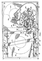
- Figure 1 is a top plan view of a preferred embodiment of our tape transport illustrating the loaded position of the leader block tape cartridge.
- Figure 2 is a top plan view of a rear portion of the tape transport of Figure 1 illustrating the leader block engaged with the take-up hub after the gear driven articulated arm has extracted the leader block from the cartridge and pulled it along the tape path to the take-up hub.
- Figure 3 is an enlarged vertical sectional view taken along line 3-3 of Fig. 1 illustrating the cartridge ejection mechanism.
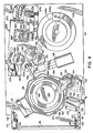
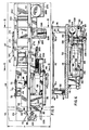
- Fig. 4 is a plan view of the underside of the preferred embodiment of our tape transport.
- Fig. 5 is a side elevation view of the preferred embodiment of our tape transport with portions of its overall housing illustrated in phantom lines.
- Fig. 6 is a vertical sectional view taken along line 6-6 of Fig. 5 illustrating the mechanisms for moving the supply reel motor and drive chuck assembly into and out of driving engagement with the supply reel hub of the leader block tape cartridge.
- Fig. 7 is a rear end elevation view of the preferred embodiment of our tape transport.
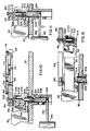
- Fig. 8 is an enlarged vertical sectional view taken along line 8-8 of Fig. 5 providing a side elevation view of a portion of the magnetic head positioner mechanism of the preferred embodiment of our tape transport.
- Fig. 9 is a sectional view taken along line 9-9 of Fig. 8 providing a rear elevation view of a portion of the magnetic head positioner.
- Fig. 10 is an enlarged vertical sectional view taken along line 10-10 of Fig. 1 illustrating the starting positions of the articulated threading arm and tape leader block capture mechanisms relative to the loaded tape cartridge.
- Fig. 11 is a view similar to Fig. 10 illustrating the capturing of the tape leader block.
- Fig. 12 is a view similar to Figs. 10 and 11 illustrating the extraction of the tape leader block and tape from the cartridge by the moving of the articulated arm along its track toward the take-up hub.
- Referring to Fig. 1, the
preferred embodiment 20 of our tape transport is illustrated with a leaderblock tape cartridge 22 fully inserted therein. The tape cartridge is of the type defined by Proposed American National Standard X3B5/85-075. The cartridge has an outer rectangular housing which encloses a supply reel 24 having ahub 26 with a length of one-half inch magnetic tape 28 (Fig. 12) wound thereabout. The free end of the magnetic tape is attached to aleader block 30 normally seated in acorner 32 of the cartridge between a forward edge 34 (Fig. 1) and aside edge 36 thereof. The cartridge housing measures approximately 125 millimeters (4 7/8 inches) in length (measured left to right in Fig. 1) by 109 millimeters (4 1/4 inches) in width (measured up and down in Fig. 1) and 24.5 millimeters (15/16 of an inch) in height (measured up and down in Fig. 10). - The transport 20 (Fig. 1) is designed to meet the industry standard 5 1/4 inch form factor. It includes an elongate, generally
rectangular housing 38 having a length L of approximately eight inches, a width W of approximately five and three-quarter inches and a height H (Fig. 5) of approximately three and one-quarter inches. The cartridge is inserted into the housing through aslot 40 in a face panel orbezel 42 connected to the forward transverse end of the housing. The forward edge 34 (Fig. 1) of the cartridge enters the slot first and theside edge 36 of the cartridge is aligned generally parallel to the longitudinally extending side edge of the housing. - Thus, bearing in mind the foregoing dimensions of the leader block tape cartridge and the housing, it will be understood that the housing has a width less than one and one-half times the width of the cartridge, and the housing has a length less than two times the length of the cartridge. The housing is also only three and one-quarter inches in height. In this extremely confined space we have provided cartridge referencing and locking, leader block extracting, supply and take-up reel drive, auto-threading, and precision head moving mechanisms, as explained in great detail hereafter.
- Several surfaces of the
cartridge 22 are engaged to register the cartridge with a predetermined reference plane. A positioner arm 44 (Fig. 5) pivoted about avertical clamp rod 46 is biased by atorsion spring 48 against theside edge 36 of the cartridge. The bottom surface of the cartridge is supported by a rectangularhorizontal base plate 50 which extends substantially the entire length and width of thehousing 38 and serves as a central mounting chassis thereof. A pair of L-shapedbrackets 52 and 54 (Figs. 1 and 5) are mounted on either side of thebase plate 50 and guide the opposite side edges of the cartridge as it is inserted into the housing. During this insertion, the positioner arm rotates counter-clockwise in Fig. 1 as its outer rounded end 56 is initially pushed out of the way by the beveled corner of the cartridge. The positioner arm presses against theside edge 36 of the cartridge to force itsopposite side edge 58 snugly against the L-shapedbracket 54. - Referring to Figs. 1 and 3, a
vertical stop plate 60 engages theforward edge 34 of the cartridge as it is inserted. The stop plate moves from an initial position illustrated in solid lines in Fig. 3 to a loaded position illustrated in phantom lines in Fig. 3 as the cartridge moves from left to right. The stop plate is affixed to asleeve 62 which longitudinally reciprocates on apost 64 mounted in a cut-out 66 (Fig. 1) in thebase plate 50. A coil spring 68 (Fig. 3) surrounding the sleeve and post is compressed upon insertion of thecartridge 22 in the housing to its fully loaded position and aids in ejecting the cartridge from the housing upon the release of cartridge locking mechanism hereafter described. This locking mechanism holds the cartridge snugly against thestop plate 60 in its loaded or retracted position illustrated in phantom lines in Fig. 3. - A horizontally extending
cross clamp 70 is releasably moved down into engagement with the upper surface of the cartridge to squeeze it against thebase plate 50. One end 70a of the cross clamp has a hole through which extends the clamp rod 46 (Fig. 6). The hole is slightly larger than the diameter of theclamp rod 46 so that the end 70a can float between the upper edge of thepositioner arm 44 and ahead 72 of the rod. The other end 70b of the cross clamp is fixed to the upper end of asecond clamp rod 74 by aretainer 76. Thecross clamp 70 does not obstruct insertion of the cartridge because thepositioner arm 46 supports its end 70a enough to keep it clear. Thesecond clamp rod 74 extends through thebase plate 50 and is vertically reciprocated by arocker arm 78 pivoted aboutpin 80 journaled in flanges 82 (Fig. 4). Acoil spring 84 surrounds the lower end of therod 74 and is compressed between apin 86 attached to the lower end of theclamp rod 74 and the underside of thebase plate 50. When a liftingbail 88 of the supply reel drive mechanism hereafter described is raised to its position illustrated in phantom lines in Fig. 6, the rocker arm pivots clockwise from its position illustrated in Fig. 6. Thespring 84 then pushes therod 74 and thecross clamp 70 downwardly, squeezing thecartridge 22 against thebase plate 50. When the lifting bail is lowered to disengage the supply reel drive mechanism, it pivots therocker arm 78 counter-clockwise, which in turn pushes thesecond clamp rod 74 and crossclamp 70 upward to their positions illustrated in Fig. 6, releasing the cartridge so that it can be ejected. - The cartridge locking mechanism includes a pair of
latches 90 and 92 (Figs. 4 and 5) having pointed ends which are moved into recesses 94 (Fig. 5) formed in the side edges of thecartridge 22. Thelatches bar 96 extends across the the forward transverse end of thehousing 38 and its opposite ends are mounted for rotation in the outer ends ofcorresponding brackets base plate 50. Torsion springs 102 and 104 (Figs. 4 and 5) surround the opposite ends of the connectingbar 96 and their legs engagepins 106 and 108 respectively on thelatches recesses 94 of the loadedcartridge 22. A latch lever 110 (Fig. 5) rotates about anaxle 112 journaled in the bracket so that one leg 110a thereof can push downwardly on the pin 108 to disengage both thelatches cartridge 22. The other end 110b of the latch lever may be pushed to the right in Fig. 5 to rotate the latch lever in a counter-clockwise direction by an eject button (not illustrated) which encloses the lever end 110b and is mounted for in and out reciprocation on theface panel 42. - A supply reel motor 114 (Fig. 4 and 5) is supported on the lifting
bail 88 for vertical reciprocation. The output shaft of this motor (not visible) is rigidly coupled to a toothed drive chuck 116 (Fig. 5) adapted to engage the serrated hub (not illustrated) of of the supply reel mounted in thecartridge 22. The liftingbail 88 is hinged to a rear support block 118 (Figs. 4 and 5) secured to the underside of thebase 50. The forward ends 120 (Fig. 4) of the lifting bail are pivotally secured to abail nut 122 which threads up and down a screw shaft 124 (Fig. 6). The opposite ends of this screw shaft are journaled in abearing 126 andbracket 128 for rotation about a vertical axis. Aspur gear 130 rigidly mounted on thescrew shaft 124 is rotated by aworm gear 132 rigidly mounted to theoutput shaft 134 of a motor 136 (Fig. 4). Themotor 136 is supported inside a mountingblock 138 secured to the underside of thebase plate 50. The flanges 82 which support therocker arm 78 extend downwardly from the underside of the mountingblock 138. - As illustrated in Fig. 6, the
motor 136 can be energized to rotate thescrew shaft 124 in opposite directions, thereby causing thebail nut 122 to thread up and down the shaft. This in turn moves the lifting bail andsupply reel motor 114 between their raised and lowered positions illustrated in phantom and solid lines, respectively, in Fig. 6. Thesupply reel motor 114 is carried by a surroundingcylindrical jacket 140. As best seen in Figs. 4 and 10, the arms of the liftingbail 88 extend betweenpins pin 146 and leaderblock actuator arm 148 extending from the other side of the jacket. As the supply reel motor is raised, the drive chuck 116 (Figs. 5 and 6) is lifted into driving engagement with the supply reel hub through a circular cut-out (not visible) in thebase plate 50. A chopper wheel 150 (Fig. 4) with a plurality of equally spaced apertures in itscircumferential periphery 152 is mounted to the lower end of the supply reel motor shaft. Theperiphery 152 of the chopper wheel rotates between a photo emitter/detector combination (not illustrated) which produces electrical signals indicative of the amount of rotation of the supply reel. - The leader block extracting mechanism of our tape transport will now be described. Referring to Figs. 1, 5 and 10, a horizontal
top cover plate 154 made DELRIN (Trademark) or other suitable rigid material is supported in spaced co-planar relationship with the rear half of thebase plate 50. The base and cover plates are rigidly connected by four vertical spacer posts 156 (Fig. 7) into which screws such as 158 (Fig. 2) are threaded at each end. A hook or generally C-shaped cut outregion 160 is formed in the top cover plate. The outer edge of the cut outregion 160 is formed with a rounded rail 162 (Figs. 2 and 8) defining a track. This track receives and guides the conformably shaped outer end 164 (Fig. 12) of the trailingarm 166 of a two-piece, articulated threading arm generally denoted 168 (Fig. 1). The trailing arm is pivotably connected to an inner orleading arm 170 whose inner end is rigidly mounted to the upper end of ashaft 172 which extends through the base and coverplates pivot pin 176 connecting the leading and trailingarms - Continuing with the description of the leader block extracting mechanism, a drive gear 178 (Fig. 1) rigidly connected with the
shaft 172 andleading arm 170 is rotated by anotherdrive gear 180 through anidler gear 182. Thedrive gear 180 is rigidly connected to the upper end of ashaft 184 which extends through the base and coverplates shaft 184 is accomplished through a gear 186 (Fig. 4) rigidly connected to the lower end of theshaft 184. Thegear 186 meshes with anothergear 188 rigidly mounted on anotherrotatable shaft 190. Anothergear 192 rigidly mounted on theshaft 190 meshes with aworm gear 194 rigidly connected to theoutput shaft 196 of anotherdrive motor 198. Themotor 198 can be selectively energized in either direction to rotate theleading arm 170 to pull the outer end of the trailingarm 166 from its leader block extraction position illustrated in Fig. 1 to its threaded position illustrated in Fig. 2. - The leader block extracting mechanism further includes a vertically extending leader block pin 200 (Fig. 10) whose upper threaded end is inserted in a hole in the outer end of the trailing
arm 166 and secured by anut 202. The lower un-threaded end of the leader block pin has anannular groove 204 formed therein. A hollow, cylindrical mountingpost 206 extends downwardly from thebase plate 50 directly beneath the location of thelower block pin 200 when it is located at the beginning of the track orrail 162 as illustrated in Fig. 1. A cylindrical locator plug 208 (Fig. 10) is mounted for vertical reciprocation within the mountingpost 206. Theplug 208 is connected to the outer end of the leaderblock actuator arm 148 which raises and lowers the plug as the supply reel drive mechanism is engaged and disengaged with thetape cartridge 22. A cylindrical deformableplastic plunger 210 is also mounted for vertical reciprocation into and out of the upper end of the hollow mountingpost 206. The cylindrical interior of theplunger 210 is formed with anannular rib 212 for snap fitting into theannular groove 204 when the plunger is slid up over theleader block pin 200. The upper end of thelocator plug 208 is provide with a fork orclevice 214 for semi-capture of alug 216 on the formed on the lower end of theplunger 210. Movement of the articulatedthreading arm 168 away from its starting position illustrated in Fig. 1 when theplunger 210 is snapped over theleader block pin 200 will result in the plunger moving free from theclevice 214 as illustrated in the successive views of Figs. 11 and 12. However, when the plunger is seated or captured in the clevice thelocator plug 208 can be lowered to pull theplunger 210 off of theleader block pin 200. - The overall tape cartridge loading operation can now be described. Prior to insertion of the leader
block tape cartridge 22 into the transport, the supply reel drive mechanism is in its lowered position illustrated in Fig. 5. The supplyreel drive motor 114 is in the position illustrated in solid lines in Fig. 6 and thedrive chuck 116 is below the upper surface of thebase plate 50 leaving an unobstructed horizontal support surface for receiving thecartridge 22. Thecartridge cross clamp 70 is also in its raised position illustrated in Fig. 6. The cartridge is inserted into the transport through the slot 40 (Fig. 5) in theface panel 42. The spring loaded latches 90 and 92 are pushed downwardly as the cartridge slides past. The spring loadedside positioner arm 44 is also pushed out of the way as the cartridge slides past. As the insertion of the cartridge continues, the spring loaded stop plate 60 (Fig. 1) engages theforward edge 34 of the cartridge and is pushed backward to its retracted position, compressingejection spring 68. While this is taking place thelatches threading arm 168 is in its retracted or starting position illustrated in Fig. 1. The leader block 30 (Fig. 10) of thetape cartridge 22 is in its retracted position inside the corner 32 (Fig. 1) of the tape cartridge. When the cartridge comes to rest, after sliding left to right in Fig. 1, in its fully loaded position, theleader block pin 200 ends up being positioned inside a vertical, outwardly opening cylindrical aperture 218 (Fig. 10) in theleader block 30. (Seecutout section 50 in U.S. Patent No. 4,452,406). - Continuing with the description of the overall tape cartridge loading operation, with the cartridge now fully inserted in the transport, a manually or automatically initiated command energizes motor 136 (Fig. 4) to cause the lifting
bail 88 to raise thesupply reel motor 114 and drivechuck 116. Thedrive chuck 116 engages the supply reel hub. The upward movement of the liftingbail 88 causesrocker arm 78 to pivot, allowing coil spring 84 (Fig. 6) to pushclamp rod 74 downwardly. This in turn causes thecross clamp 70 to squeeze downwardly against the upper surface of thetape cartridge 22. The upward movement of the liftingbail 88 also causes arm 148 (Fig. 10) to raise thelocator plug 208 andconnected plunger 210. Theplunger 210 is raised into thecylindrical aperture 218 and snaps over theleader block pin 200 as illustrated in Fig. 11. The motor 198 (Fig. 4) is then energized to rotate leading arm 170 (Fig. 1) in a counter-clockwise direction. The opening in therecess 218 in the leader block is large enough to permit free entry and exist of the nakedleader block pin 200, but not theplunger 210. Therefore, when the trailingarm 166 pulls away from the cartridge it pulls theleader block 30 and themagnetic tape 28 with it, as illustrated in Fig. 12. - Referring to Fig. 1, a take-up
reel 219 comprising ahub 220 and upper andlower butterfly flanges 222 is mounted for rotation about a vertical axis between the base andtop cover plates cartridge 22 and the take-up reel thus rotate in the same general plane. The take-up hub has a radially extending, outwardly openingchannel 224 formed therein into which the joinedleader block pin 200,plunger 210 andleader block 30 are pulled by the articulatedthreading arm 168 as illustrated in Fig. 2. As the articulatedthreading arm 168 moves between its beginning and ending positions illustrated in Figs. 1 and 2, respectively, themagnetic tape 28 from the cartridge is threaded past a magnetic read/write/erase transducer assembly 226 (Fig. 1), and generally along the tape path bounded by the cut outregion 160 in thetop cover plate 154. The take-up real is rigidly mounted to the upper end of the shaft of a take-up drive motor 228 ( Fig. 7). Achopper wheel 229a (Fig. 4) is coupled to the lower end of the shaft of the take-upmotor 228. A photo emitter/detector combination 229b through which the periphery of thechopper wheel 229a spins provides electrical signals representative of the angular position of the shaft of the take-up motor. Prior to the loading of the tape cartridge, the empty take-up reel is automatically positioned so that thechannel 224 in the take-up hub is positioned as illustrated in Fig. 1, ready to receive theleader block 30 when it is pulled thereto by the articulatedthreading arm 168. When the articulatedarm 168 is in its end or threaded position illustrated in Fig. 2, the take-upmotor 226 can be energized to rotate the take-upreel 219. The vertical axis of theleader block pin 200 coincides with the rotational axis of the take-up hub so that theleader block 30 andplunger 210 positioned therein rotate inside thechannel 224 about thepin 200. Themagnetic tape 28 is then wound around the take-uphub 224. - When the
tape cartridge 22 is to be withdrawn from the transport, the tape on the take-up reel is first rewound into the cartridge. The take-up reel is stopped in its position illustrated in Fig. 2 so that theleader block 30 can be extracted from thechannel 224 in the take-up hub upon clockwise rotation of theleading arm 170. Continued clockwise rotation of the leading arm results in the trailingarm 166 pulling theleader block 30 and terminal end of themagnetic tape 28 connected thereto back along the C-shapedtrack 162 to the position illustrated in Fig. 1. There the leader block is snapped back into thecorner 32 of the tape cartridge. During this process the terminal end of the magnetic tape is re-wound about the supply reel inside the tape cartridge. - The receptacle inside the
corner 32 of tape cartridge that receives theleader block 30 is formed so that the leader block snaps in place. The leader block must be pulled in a particular direction in order to be snapped out of the cartridge. Referring to Fig. 1, mounted onshaft 184 beneathgear 180, which is shown broken away, is a cam 230 having a peripheral recess in which apawl 232 extending from the trailingarm 166 is received. Certain teeth are also missing from the periphery of thegear 180 at the correct angular location. When thethreading arm 168 is in its beginning position illustrated in Fig. 1, the initial counter-clockwise turning of thegear 180 by thedrive motor 198 causes thecurved shoulder 234 of the cam 230 to engage thepawl 232 and pull the trailingarm 166 downward and to the right in Fig. 1. This unsnaps theleader block 30 from thetape cartridge 22 before the teeth of thegear 180 begin to mesh with those of theidler gear 182 which in turn rotates thegear 178 and theleading arm 170 in a clockwise direction. Upon rewinding of the tape, the teeth of thegear 180 disengage those of theidler gear 182 just as theleader block 30 gets near the final insertion location into the tape cartridge. Theother shoulder 236 of the cam 230 then pushes thepawl 232 as the can continues to rotate clockwise. This forces the end of the trailingarm 166 up and to the left in Fig. 1. This in turn forcefully snaps theleader block 30 in place. The foregoing linkage serves as a clutching arrangement to prevent overdriving the articulatedthreading arm 168 and damaging the guide track, threading arm, motor or gear train. - Referring to Fig. 2, the tape path includes tape guide blocks or
chutes transducer assembly 226. Atape guide roller 242 is also mounted downstream of theguide block 240 for directing themagnetic tape 28 to the take-up reel. A movable tape guide roller 244 (Fig. 1) is mounted for articulated movement into engagement with the magnetic tape in advance of the leadtape guide block 238 after the leader block has been pulled past the same. Referring to Fig. 5, the guide roller is supported by an axle connected at its ends to upper andlower arms 246. The inner ends of these arms are rigidly connected to a vertical post 248 rigidly connected to the upper end of ashaft 250 which extends through thebase plate 50. Aknurled disk 252 is rigidly connected to the lower end of theshaft 250, beneath thebase plate 50. A coil spring 254 (Fig. 4) is connected between aeccentric pin 256 on theknurled disk 252 and abracket 258. Thespring 254 biases theroller 244 toward themagnetic tape 28. Ametal drive wheel 258 with a deformableouter tire 260 is mounted for rotation on ashaft 262 so that the tire is in driving engagement with theknurled disk 252. The upper end of theshaft 262 is connected to thebase plate 50. A cam 264 is rigidly mounted on theshaft 184. This cam is specially configured and oriented to achieve the following drive action. Themotor 198 initially rotates the shaft 184 a sufficient amount to cause the articulated threading arm to pull the leader block past themovable guide roller 244. Thereafter the cam 264 will engage thetire 260 to causearms 246 to rotate and bring theguide roller 244 into contact with the magnetic tape to thereby establish the proper tape wrap angle. When the leader block is pulled back to the tape cartridge by the articulated arm, a reverse drive action takes place to swing themovable guide roller 244 clear of the tape path, clearing the way for the next threading operation on a subsequently loaded tape cartridge. - The precision magnetic
head positioner mechanism 266 of our tape transport will now be described by way of reference to Figs. 4, 7, 8 and 9. Briefly, the red/write/erasetransducer assembly 226 is supported and moved vertically up and down in precise, minute increments to access a selected one of a plurality of parallel data tracks, for example, twenty-four, extending longitudinally along the half-inch magnetic tape. A stepper motor 268 (Fig. 4) is mounted on an angularlybent segment 270 of ametal mounting plate 272 secured to the underside of thebase plate 50. A worm gear 274 (Fig. 7) rigidly connected to the end of the shaft of the stepper motor meshes with apinion gear segment 276 rigidly mounted to one end of a horizontal axle 278 (Fig. 4) rotatably journaled in an elongate bearinghousing 280. A drum 282 (Fig. 8) is rigidly mounted to the other end of theaxle 278. - Continuing with the description of the
head positioner mechanism 266, the transducer assembly 226 (Fig. 8) is mounted on acarriage 284 supported onprecision bearings post 290. The intermediate portion of a non-elastic band 292 (Figs. 8 and 9) made of, for example, metal foil is wrapped around thedrum 282 and is secured thereto byset screw 294. The upper end of the metal band is secured to the upper portion of thecarriage 284. The lower end of themetal band 292 is secured to one end of alever 296 pivoted at the lower end of the carriage. Acoil spring 298 connects the other end of the lever to the carriage body. It will be readily understood that selective energization of thestepper motor 268 will rotate thedrum 282 to wind different portions of themetal band 292 about the drum to thereby reciprocate thecarriage 284 and thetransducer assembly 226 carried thereby. - The electronic circuitry for handling all the reading and writing of digital data to and from the magnetic tape and for communicating with the host computer may be carried on two rectangular printed circuit boards not illustrated. These boards may be mounted horizontally within the housing, one above and cartridge and take-up hub, and the other below the supply and take-up motors. By way of example, this circuitry may include an SCSI/QIC-02 I/F Controller Driver Chip, a 80188 16-bit microprocessor, 32 KBytes of CMOS EPROM, 8 KBytes of CMOS RAM, 64 KBytes of Tape Image Buffer, a tape image buffer controller chip, a write interface chip, a write driver, a read channel, a data separator, and a read interface chip. The circuitry may further include electronic components interconnected as is well known in the tape drive art to provide electro-mechanical interface with the reel motor drivers, head position stepper motor, chuck engage motor, threading motor driver, tachometer interface, sense switch interface and LED driver.
- Our tape transport is capable of operating in a "streaming" mode, and may simulate fast acceleration start/stop tape drives as well. Our transport has no tape capstan. Instead, the currents to the supply and take-up motors are controlled as is well known in the art to maintain constant tape tension. See U. S. Patent No. 4,125,881 of Eige et al., entitled "Tape Motion Control for Reel-To-Reel Drive", the disclosure of which is specifically incorporated herein by reference. See also U. S. Patent No. 4,500,965 of Gray, entitled "Capstanless Magnetic Tape Drive with Electronic Equivalent to Magnetic Tape" the disclosure of which is specifically incorporated herein by reference.
- Our tape transport, when equipped with electronics such as those briefly summarized above, may provide a storage capacity, on the Proposed ANSI X3B5/85-075 one-half inch leader block tape cartridge, of 200 megabytes of formatted data.
- In summary, we have designed a tape transport for the referenced leader block tape transport that will fit within the industry standard 5 1/4 inch form factor, while still providing all the essential functions to allow reliable reading and writing of data at extremely high densities and permitting interchangeability of cartridges between various drives. Thus, our invention enables small computer owners to have a device that provides extremely cost effective, reliable mass data storage for data interchange, archival storage and back-up protection.
Claims (4)
- A transport (20) for a rectangular tape cartridge (22) enclosing a supply reel (24) having a web of magnetic tape (28) wound thereabout, the transport comprising an elongate, generally rectangular housing (38) sized for having the cartridge inserted therein at a forward transverse end of the housing through a slot (40) in a face panel (42), a supply reel motor (114) for driving a chuck (116) engageable with a supply reel hub (26), a take-up motor (228) for driving a take-up hub (220), a tape path extending between the supply reel (24) and the take-up hub (220) including a transducer assembly (226) and tape guide blocks (238,240) mounted on either side thereof, whereby
the web of tape terminates in a leader block (30) normally seated in a corner of the tape cartridge (22) between a forward edge (34) and a side edge (36) thereof; and
the transport further comprises a two-piece articulated threading arm (168) having an inner end rotated by a motor (198) and an outer end having a leader block pin (200) movable into a recess (218) in the leader block (30) and means (210) for permitting the pin (200) to capture the leader block so that it can be pulled by the arm (168) into a channel (224) in the take-up hub (220) to thread the tape (28) past the transducer assembly (226); characterized by
a C-shaped track (160,162) formed in a cover plate (154) for engaging the outer end of the threading arm (168) to guide the same along the tape path whereby the transport can be made compact with the housing (38) having a width less than one and one-half times a width of the cartridge and the housing having a length less than two times a length of the cartridge, whereby the threading arm (168) is rotated by the motor (198) via gear drive means (178,180,182,186,188,192,194). - A transport according to claim 1 and further characterized in that the housing includes means (70,74,78,88) for releasably clamping the cartridge (22) against a reference surface (50).
- A transport according to claim 1 or 2 and further characterized in that head positioner means (266) are provided including a stepper motor (268) that moves the transducer assembly (226) via a non-elastic band (292) wound about a drum (282).
- A transport according to claim 1, 2 or 3 and further characterized in that an articulated tape guide roller (244) is provided along the tape path in advance of the lead tape guide block (238).
Applications Claiming Priority (2)
| Application Number | Priority Date | Filing Date | Title |
|---|---|---|---|
| US06/794,503 US4704645A (en) | 1985-11-01 | 1985-11-01 | Transport for tape cartridge with leader block |
| US794503 | 1985-11-01 |
Publications (3)
| Publication Number | Publication Date |
|---|---|
| EP0221762A2 EP0221762A2 (en) | 1987-05-13 |
| EP0221762A3 EP0221762A3 (en) | 1988-07-27 |
| EP0221762B1 true EP0221762B1 (en) | 1993-05-12 |
Family
ID=25162813
Family Applications (1)
| Application Number | Title | Priority Date | Filing Date |
|---|---|---|---|
| EP86308401A Expired - Lifetime EP0221762B1 (en) | 1985-11-01 | 1986-10-29 | Transport for tape cartridge with leader block |
Country Status (4)
| Country | Link |
|---|---|
| US (2) | US4704645A (en) |
| EP (1) | EP0221762B1 (en) |
| JP (1) | JP2739470B2 (en) |
| DE (1) | DE3688420D1 (en) |
Cited By (1)
| Publication number | Priority date | Publication date | Assignee | Title |
|---|---|---|---|---|
| US8221009B2 (en) | 2000-09-11 | 2012-07-17 | Zipher Limited | Tape drive and printing apparatus |
Families Citing this family (34)
| Publication number | Priority date | Publication date | Assignee | Title |
|---|---|---|---|---|
| US4805045A (en) * | 1986-03-21 | 1989-02-14 | Laser Magnetic Storage International Company | Apparatus for loading and unloading a tape cartridge |
| US4828201A (en) * | 1986-03-21 | 1989-05-09 | Laser Magnetic Storage International Company | Apparatus for coupling a drive motor to a leader block loading/unloading mechanism |
| US4826101A (en) * | 1986-03-21 | 1989-05-02 | Smith Jay A | Apparatus for loading and unloading the leader block of a tape cartridge |
| JPS63108551A (en) * | 1986-10-27 | 1988-05-13 | Nakamichi Corp | Leader block pulling-out device |
| JPH0447787Y2 (en) * | 1986-11-10 | 1992-11-11 | ||
| JPH056592Y2 (en) * | 1987-05-27 | 1993-02-19 | ||
| JPH01192049A (en) * | 1988-01-27 | 1989-08-02 | Nakamichi Corp | Magnetic recording and reproducing device |
| US4852825A (en) * | 1988-09-14 | 1989-08-01 | Cipher Data Products, Inc. | Extraction and insertion mechanism for a leader block of a tape cartridge |
| US5155639A (en) * | 1988-11-03 | 1992-10-13 | U.S. Philips Corporation | Transport apparatus for a single reel tape cartridge |
| JPH0268344U (en) * | 1988-11-10 | 1990-05-23 | ||
| JPH02134687A (en) * | 1988-11-15 | 1990-05-23 | Sharp Corp | Display controller |
| US5144513A (en) * | 1989-06-21 | 1992-09-01 | Data Pure Corporation | Method and apparatus for cleaning magnetic tape having air bearings and vacuum-assisted cleaning |
| US4949914A (en) * | 1989-07-03 | 1990-08-21 | Cipher Data Products, Inc. | Tape transport with rigid arm threader mechanism for leader block tape cartridge |
| JP2640692B2 (en) * | 1990-07-18 | 1997-08-13 | 富士通株式会社 | Tape threading mechanism of magnetic tape device and method of controlling tape threading mechanism |
| US5243477A (en) * | 1991-12-17 | 1993-09-07 | Datatape Incorporated | Apparatus for threading magnetic tape from a single reel cartridge in a rotary head tape transport |
| US5219129A (en) * | 1992-02-20 | 1993-06-15 | Storage Technology Corporation | Tape threading mechanism |
| US5333810A (en) * | 1993-05-13 | 1994-08-02 | Storage Technology Corporation | Raised linear threading mechanism for a tape transport system |
| EP0630011A3 (en) * | 1993-06-14 | 1996-02-21 | Ibm | Bi-directional reel-to-reel tape drive. |
| US6241171B1 (en) * | 1998-03-26 | 2001-06-05 | Quantum Corporation | Leaderless tape drive |
| US6257514B1 (en) * | 1999-06-25 | 2001-07-10 | Benchmark Tape Systems Corporation | Guiding assembly for protecting a magnetic tape head |
| US6378796B1 (en) * | 1999-10-08 | 2002-04-30 | Seagate Technology Llc | Apparatus and method for de-coupling grabber from take-up reel |
| US7455254B1 (en) | 2000-07-25 | 2008-11-25 | Certance Llc | Method and apparatus of maintaining tension in a tape |
| US7252257B2 (en) * | 2000-11-13 | 2007-08-07 | Sony Corporation | Tape drive apparatus, tape extraction apparatus and tape cassette |
| US6644580B2 (en) | 2000-11-29 | 2003-11-11 | Fujitsu Limited | Take up assembly for wrapping spaced tape portions |
| US6565028B2 (en) * | 2000-11-29 | 2003-05-20 | Fujitsu Limited | Tape pin load/unload control mechanism |
| JP3979208B2 (en) * | 2002-07-22 | 2007-09-19 | ソニー株式会社 | Recording and / or playback device |
| JP3783683B2 (en) * | 2003-01-16 | 2006-06-07 | 日本電気株式会社 | Leader block rotation mechanism of cartridge magnetic tape device |
| US7077354B2 (en) * | 2003-01-21 | 2006-07-18 | Quantum Corporation | Edge guiding tape reel |
| US20040140392A1 (en) * | 2003-01-21 | 2004-07-22 | George Saliba | Butterfly tape reel |
| US7073742B2 (en) * | 2003-01-21 | 2006-07-11 | Quantum Corporation | Tape guiding reel |
| US7147930B2 (en) | 2003-12-16 | 2006-12-12 | Curwood, Inc. | Heat-shrinkable packaging films with improved sealing properties and articles made thereof |
| US7426095B1 (en) | 2005-11-30 | 2008-09-16 | Storage Technology Corporation | Media drive having a head positioning assembly utilizing a rotatable and slidable nut engaging a threaded screw |
| KR101589920B1 (en) * | 2015-09-30 | 2016-01-29 | 손동찬 | Cartridge headshell, tone arm and audio turntable having it |
| US10614833B2 (en) | 2015-09-30 | 2020-04-07 | Dong-Chan SON | Headshell and tonearm for mounting cartridge of audio turntable and audio turntable comprising same |
Citations (1)
| Publication number | Priority date | Publication date | Assignee | Title |
|---|---|---|---|---|
| EP0074476A1 (en) * | 1981-10-26 | 1983-03-23 | International Business Machines Corporation | Web threading apparatus |
Family Cites Families (22)
| Publication number | Priority date | Publication date | Assignee | Title |
|---|---|---|---|---|
| JPS4111955Y1 (en) * | 1964-07-21 | 1966-06-04 | ||
| US3951357A (en) * | 1972-03-08 | 1976-04-20 | Ricoh Co., Ltd. | Automatic cartridge tape draw-out device |
| US4023748A (en) * | 1974-08-19 | 1977-05-17 | Basf Aktiengesellschaft | Cassette loading and tape tensioning system |
| US4161004A (en) * | 1977-04-05 | 1979-07-10 | Shugart Associates | Head positioning mechanism for recording/playback machine |
| US4125881A (en) * | 1977-05-19 | 1978-11-14 | International Business Machines Corporation | Tape motion control for reel-to-reel drive |
| JPS5485707A (en) * | 1977-12-20 | 1979-07-07 | Nec Corp | Magnetic recorder-reproducer of 2 tape cartridge type |
| US4334656A (en) * | 1980-06-30 | 1982-06-15 | International Business Machines Corporation | Automatic tape threading apparatus for magnetic tape transports |
| US4335858A (en) * | 1980-06-30 | 1982-06-22 | International Business Machines Corporation | Apparatus for threading tape over a tape path including a channel conforming to said path |
| US4383660A (en) * | 1981-03-30 | 1983-05-17 | International Business Machines Corp. | Single reel tape cartridge with leader block door seal |
| JPS58140563U (en) * | 1982-03-11 | 1983-09-21 | 株式会社東芝 | head mechanism |
| US4452406A (en) * | 1982-03-26 | 1984-06-05 | International Business Machines Corporation | Leader block for single reel tape cartridge |
| US4426047A (en) * | 1982-03-26 | 1984-01-17 | International Business Machines Corp. | Single reel tape cartridge |
| US4500965A (en) * | 1982-06-04 | 1985-02-19 | Cipher Data Products, Inc. | Capstanless magnetic tape drive with electronic equivalent to length of tape |
| US4477851A (en) * | 1982-06-07 | 1984-10-16 | Microtek Storage Corporation | Magnetic data storage and drive apparatus |
| JPS5913097A (en) * | 1982-07-10 | 1984-01-23 | Nippon Steel Corp | Material for insoluble anode for electroplating |
| JPS59140662A (en) * | 1983-01-31 | 1984-08-13 | Hitachi Ltd | Automatic tape loading device |
| US4608614A (en) * | 1983-06-24 | 1986-08-26 | International Business Machines Corp. | Apparatus for threading magnetic tape in a magnetic tape transport |
| US4646177A (en) * | 1983-11-25 | 1987-02-24 | Electronic Processors, Inc. | Automatic tape threading system for use in a tape transport system |
| EP0143598A3 (en) * | 1983-11-25 | 1986-09-03 | Electronic Processors, Inc. | Magnetic tape recording and reproducing system with automatic tape threading |
| US4555077A (en) * | 1983-11-25 | 1985-11-26 | Electronic Processors, Inc. | Tape cartridge |
| US4679747A (en) * | 1986-03-21 | 1987-07-14 | Laser Magnetic Storage International Company | Apparatus for loading and unloading the leader block of a tape cartridge |
| US4742407A (en) * | 1986-06-11 | 1988-05-03 | Aspen Peripherals | Tape threading device |
-
1985
- 1985-11-01 US US06/794,503 patent/US4704645A/en not_active Expired - Lifetime
-
1986
- 1986-10-29 DE DE8686308401T patent/DE3688420D1/en not_active Expired - Lifetime
- 1986-10-29 EP EP86308401A patent/EP0221762B1/en not_active Expired - Lifetime
- 1986-10-31 JP JP61261738A patent/JP2739470B2/en not_active Expired - Lifetime
-
1988
- 1988-05-16 US US07/195,408 patent/US4809099A/en not_active Expired - Lifetime
Patent Citations (1)
| Publication number | Priority date | Publication date | Assignee | Title |
|---|---|---|---|---|
| EP0074476A1 (en) * | 1981-10-26 | 1983-03-23 | International Business Machines Corporation | Web threading apparatus |
Cited By (5)
| Publication number | Priority date | Publication date | Assignee | Title |
|---|---|---|---|---|
| US8221009B2 (en) | 2000-09-11 | 2012-07-17 | Zipher Limited | Tape drive and printing apparatus |
| US8221010B2 (en) | 2000-09-11 | 2012-07-17 | Zipher Limited | Tape drive and printing apparatus |
| US8328441B2 (en) | 2000-09-11 | 2012-12-11 | Videojet Technologies (Nottingham) Limited | Tape drive and printing apparatus |
| US8591127B2 (en) | 2000-09-11 | 2013-11-26 | Videojet Technologies (Nottingham) Limited | Tape drive and printing apparatus |
| US9233553B2 (en) | 2000-09-11 | 2016-01-12 | Videojet Technologies (Nottingham) Limited | Tape drive and printing apparatus |
Also Published As
| Publication number | Publication date |
|---|---|
| US4809099A (en) | 1989-02-28 |
| EP0221762A2 (en) | 1987-05-13 |
| DE3688420D1 (en) | 1993-06-17 |
| JPS62119766A (en) | 1987-06-01 |
| JP2739470B2 (en) | 1998-04-15 |
| US4704645A (en) | 1987-11-03 |
| EP0221762A3 (en) | 1988-07-27 |
Similar Documents
| Publication | Publication Date | Title |
|---|---|---|
| US4809099A (en) | Transport for tape cartridge with leader block | |
| EP0035548B1 (en) | Data cartridge recorder with head positioning mechanism | |
| JP3338442B2 (en) | Autoloader for magnetic tape cartridge | |
| US5045958A (en) | Positioner for magnetic tape cartridge magazine | |
| EP0302176B1 (en) | Magnetic recording and reproducing apparatus | |
| JPS62277656A (en) | Apparatus for connecting reader block loading/unloading mechanism to drive motor | |
| EP0560859B1 (en) | Tape cartridge transport apparatus for helical scaning of the tape | |
| EP0368667A3 (en) | A magnetic recording and reproducing apparatus | |
| US3751042A (en) | Magnetic tape transport | |
| EP0082014A1 (en) | Tape cassette adapter | |
| US4247876A (en) | Dictation recording and transcribing system utilizing a multiple media cartridge apparatus | |
| US4991037A (en) | Apparatus for manipulating a magnetic tape cartridge and the magnetic tape contained therewithin | |
| EP0354783B1 (en) | Magnetic recording/reproducing apparatus for selective use with tape cassettes of two different sizes | |
| JPH0447787Y2 (en) | ||
| US5012364A (en) | Tape-loading mechanism for a magnetic recording/reproducing apparatus for selective use of tape cassettes of two different sizes | |
| US4949914A (en) | Tape transport with rigid arm threader mechanism for leader block tape cartridge | |
| US3959822A (en) | Magnetic tape transport for positive coupling of cassette tape reels | |
| US4519009A (en) | Dictation recording and transcribing system utilizing a multiple media cartridge apparatus | |
| US7283318B2 (en) | Position sensor | |
| EP0142565A1 (en) | Magnetic recording and reproducing apparatus | |
| US3890642A (en) | Magnetic tape transport | |
| EP0326369A3 (en) | A magnetic recording and reproducing apparatus | |
| JPS6379263A (en) | Magnetic tape threading mechanism | |
| JPS5982252A (en) | Tape taking out device | |
| JPH03272049A (en) | Information recording and reproducing device |
Legal Events
| Date | Code | Title | Description |
|---|---|---|---|
| PUAI | Public reference made under article 153(3) epc to a published international application that has entered the european phase |
Free format text: ORIGINAL CODE: 0009012 |
|
| AK | Designated contracting states |
Kind code of ref document: A2 Designated state(s): DE FR GB IT |
|
| PUAL | Search report despatched |
Free format text: ORIGINAL CODE: 0009013 |
|
| AK | Designated contracting states |
Kind code of ref document: A3 Designated state(s): DE FR GB IT |
|
| 17P | Request for examination filed |
Effective date: 19890119 |
|
| 17Q | First examination report despatched |
Effective date: 19900529 |
|
| RAP1 | Party data changed (applicant data changed or rights of an application transferred) |
Owner name: ARCHIVE CORPORATION |
|
| GRAA | (expected) grant |
Free format text: ORIGINAL CODE: 0009210 |
|
| AK | Designated contracting states |
Kind code of ref document: B1 Designated state(s): DE FR GB IT |
|
| PG25 | Lapsed in a contracting state [announced via postgrant information from national office to epo] |
Ref country code: IT Free format text: LAPSE BECAUSE OF FAILURE TO SUBMIT A TRANSLATION OF THE DESCRIPTION OR TO PAY THE FEE WITHIN THE PRESCRIBED TIME-LIMIT;WARNING: LAPSES OF ITALIAN PATENTS WITH EFFECTIVE DATE BEFORE 2007 MAY HAVE OCCURRED AT ANY TIME BEFORE 2007. THE CORRECT EFFECTIVE DATE MAY BE DIFFERENT FROM THE ONE RECORDED. Effective date: 19930512 Ref country code: DE Effective date: 19930512 Ref country code: FR Effective date: 19930512 |
|
| REF | Corresponds to: |
Ref document number: 3688420 Country of ref document: DE Date of ref document: 19930617 |
|
| EN | Fr: translation not filed | ||
| PG25 | Lapsed in a contracting state [announced via postgrant information from national office to epo] |
Ref country code: GB Effective date: 19931029 |
|
| GBPC | Gb: european patent ceased through non-payment of renewal fee |
Effective date: 19931029 |
|
| PLBE | No opposition filed within time limit |
Free format text: ORIGINAL CODE: 0009261 |
|
| STAA | Information on the status of an ep patent application or granted ep patent |
Free format text: STATUS: NO OPPOSITION FILED WITHIN TIME LIMIT |