EP0221652B1 - Improvements in or relating to power tools - Google Patents
Improvements in or relating to power tools Download PDFInfo
- Publication number
- EP0221652B1 EP0221652B1 EP86307006A EP86307006A EP0221652B1 EP 0221652 B1 EP0221652 B1 EP 0221652B1 EP 86307006 A EP86307006 A EP 86307006A EP 86307006 A EP86307006 A EP 86307006A EP 0221652 B1 EP0221652 B1 EP 0221652B1
- Authority
- EP
- European Patent Office
- Prior art keywords
- tool
- passage
- valve
- passages
- housing
- Prior art date
- Legal status (The legal status is an assumption and is not a legal conclusion. Google has not performed a legal analysis and makes no representation as to the accuracy of the status listed.)
- Expired - Lifetime
Links
Images




Classifications
-
- B—PERFORMING OPERATIONS; TRANSPORTING
- B23—MACHINE TOOLS; METAL-WORKING NOT OTHERWISE PROVIDED FOR
- B23D—PLANING; SLOTTING; SHEARING; BROACHING; SAWING; FILING; SCRAPING; LIKE OPERATIONS FOR WORKING METAL BY REMOVING MATERIAL, NOT OTHERWISE PROVIDED FOR
- B23D59/00—Accessories specially designed for sawing machines or sawing devices
- B23D59/006—Accessories specially designed for sawing machines or sawing devices for removing or collecting chips
- B23D59/0062—Accessories specially designed for sawing machines or sawing devices for removing or collecting chips by blowing
-
- B—PERFORMING OPERATIONS; TRANSPORTING
- B23—MACHINE TOOLS; METAL-WORKING NOT OTHERWISE PROVIDED FOR
- B23D—PLANING; SLOTTING; SHEARING; BROACHING; SAWING; FILING; SCRAPING; LIKE OPERATIONS FOR WORKING METAL BY REMOVING MATERIAL, NOT OTHERWISE PROVIDED FOR
- B23D59/00—Accessories specially designed for sawing machines or sawing devices
- B23D59/006—Accessories specially designed for sawing machines or sawing devices for removing or collecting chips
- B23D59/0064—Accessories specially designed for sawing machines or sawing devices for removing or collecting chips by suction
-
- B—PERFORMING OPERATIONS; TRANSPORTING
- B23—MACHINE TOOLS; METAL-WORKING NOT OTHERWISE PROVIDED FOR
- B23Q—DETAILS, COMPONENTS, OR ACCESSORIES FOR MACHINE TOOLS, e.g. ARRANGEMENTS FOR COPYING OR CONTROLLING; MACHINE TOOLS IN GENERAL CHARACTERISED BY THE CONSTRUCTION OF PARTICULAR DETAILS OR COMPONENTS; COMBINATIONS OR ASSOCIATIONS OF METAL-WORKING MACHINES, NOT DIRECTED TO A PARTICULAR RESULT
- B23Q11/00—Accessories fitted to machine tools for keeping tools or parts of the machine in good working condition or for cooling work; Safety devices specially combined with or arranged in, or specially adapted for use in connection with, machine tools
- B23Q11/0042—Devices for removing chips
- B23Q11/006—Devices for removing chips by sucking and blowing simultaneously
Definitions
- This invention relates to power tools and has particular, but not exclusive, reference to hand-held power tools, for example jig-saws, sabre saws, plaster saws and routers.
- the suction passage is joined to a source of vacuum external of the tool.
- a power tool having both a passage for directing an air blast on to the work area and a suction passage for drawing debris therefrom and in which the suction passage is operable in an effective manner.
- a power tool comprises a housing accommodating a mechanism for driving a tool piece and in which there is provided a first passage arranged to direct an air flow towards a work area of the tool, and in which there is also provided a second passage extending away from the work area, characterised in that valve means are provided for selectively opening and closing the first and second passages.
- first and second passages share a common outlet adjacent the work area.
- first and second passages merge into a single passage having an outlet adjacent the work area.
- the valve means may be located in or adjacent the common outlet or in the single passage.
- the valve means may comprise a valve in the first passage and a separate valve in the second passage.
- the valve and the separate valves may operatively be linked together in a manner such that as one of the first and second passages is closed, the other thereof is opened.
- the valve means may be such that both first and second passages cannot be open simultaneously.
- the valve means may comprise a single valve member having a first position in which one of the first and second passages is open and the other thereof closed, and a second position in which the one passage is closed and the other passage open.
- the single valve member may be rotatable from one position to the other.
- the valve member may be housed in one of the first and second passages and partly in the other.
- the valve member may be of generally cylindrical form having a central semi-cylindrical portion which in the first position closes the one passage and in the other position closes the other passage.
- Stop means may be provided for limiting the rotational movement of the valve member to about 180 ° of arc.
- the driving mechanism may include a driving motor and a fan for circulating air over the motor, and in which the first passage is positioned to receive a part of the air circulated by the fan.
- the second passage may be adapted, at its other end, for connection to a source of vacuum separate from the tool.
- the housing may include means for withdrawing air along the second passage from the one end thereof.
- Both first and second passages may be accommodated within the housing which may be of two part construction, the said passages being formed by co-operating portions of the housing parts.
- the jig-saw shown in side elevation in Fig. 1 has a housing 1 of two-part clam shell construction with a shoe 2 attached to the lower part of the housing.
- the housing 1 is formed to provide a handle portion 3.
- the housing 1 accommodates an electric motor and a drive mechanism for reciprocating a saw blade drive shaft (not shown) to whose lower end a saw blade 4 is secured by means of a releasable clamp 5.
- the motor and drive mechanism are of conventional form.
- Power is supplied to the motor via a cable 6 and is controlled by a switch (not shown) operated by a trigger 7 with a 'lock-on' button 8.
- a guard 9 of a transparent plastics material Slidably mounted upon the front of the housing 1 is a guard 9 of a transparent plastics material.
- the guard 9 occupies the position in which it is shown in Fig. 1 when the jig-saw is not in use.
- the guard 9 is slid downwardly to a position in which the lower edges of small projections 12 rest on the forward end of the shoe 2.
- the guard 9 On its inner face, the guard 9 has small projections indicated diagrammatically at 10 and 11 which co-operates with depressions in the surface of the housing 1 to hold the guard in position.
- the guard When in its lowered position, the guard forms a protective shield around the front of the saw blade 4 without obscuring the user's view thereof. There is also a narrow gap left between the lower edge 13 of the guard and the upper surface of the shoe 2 whose purpose will be described below.
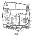
- the housing 1 is formed from two housing parts of a suitable plastics material, 14 - Fig. 2 and 15 - Fig. 3, that are formed around their mating edges with co-operating stepped surface 16 that engage when the parts are placed together.
- the parts are secured together by screws (not shown) that pass through holes 17 in part 14 and into bosses 18 located in part 15 in positions corresponding with those of the holes 17.
- the parts 15 and 16 are contoured to provide a space 19 for the motor and an adjacent space 20 for the mechanism for reciprocating the saw blade.
- the armature shaft of the motor carries a fan which circulates air over the motor during use to cool the latter.
- the housing parts 14, 15 have air inlet slots 21, 22 respectively through which the fan draws in air and outlet slots 23, 24 through which a part of the cooling air flow exits to atmosphere.
- Each housing part 14, 15 also has ribs 25, 26 respectively in the space 19 for supporting the motor and bosses 27, 28 respectively in the space 20 for locating and supporting the mechanism for reciprocating the saw blade.
- a wall separates the spaces 19 and 20 and is formed by parts 30, 31 of the housing parts 14, 15 respectively.
- the wall parts 30, 31 are contoured in a manner such that, when the housing parts are placed together, an aperture is formed in the wall which also helps to locate the reciprocating mechanism and also accommodates the drive from the shaft of the motor to that mechanism.
- the lower part of the space 19 is bounded by a transverse wall formed by half walls 32, 33 of the housing parts 14, 15 respectively. That tranverse wall is the upper boundary of a suction passage 34 whose lower surface is, in part, the lower incurved surfaces 35, 36 of the housing parts 14, 15 and in part the surface of a short wall composed of wall parts 37, 38.
- the wall parts 37, 38 are separated from the adjacent incurved surfaces of the housing parts to accommodate recesses 39 in which locate nuts (not shown) which receive screws (not shown) which secure the shoe 2 to the housing 1.
- suction passage 34 joins a downwardly inclined portion 40 formed between ribs 41, 42 of the housing parts.
- the portion 40 terminates in an outlet adjacent the saw blade 4 in the vicinity of the work area thereof.
- each housing part has a mounting adjacent rib 41 whose function will be described below.
- wall parts 32, 33 curve upwardly towards an exit aperture 43 formed between the parts 15 and 16 at the rear of the housing 1. Adjacent the aperture 43, the parts 14, 15 have internal ribs 44, 45 respectively which between them locate and support a short tube (not shown) that is flanged at one end, the flange locating on the inner side of the ribs 44, 45.
- a second short passage 46 is formed above the portion 40 between the ribs 41 and further ribs 47 of the housing parts.
- This passage 46 forms a "blow" passage and has a downward inclination similar to that of portion 40 which it joins at its lower end. At its upper end, passage 46 terminates in the vicinity of the motor cooling fan and adjacent the exit slots 23, 24.
- a flow control valve 48 Positioned laterally across portion 40 is a flow control valve 48 shown in perspective view in Fig. 12 and diagrammatically in Figs. 13 and 14.
- the valve 48 is of generally overall cylindrical form with a stub axle 49 at one end and a locking peg 50 formed on a second stub axle 49 at the other.
- the axle 49 is slotted as at 51 to enable a user to rotate the valve as will be described in more detail below.
- the valve is cut away as at 52 to form a semitubular sealing member 53.
- the valve 48 seats in the mountings referred to above and which are referenced 54 in Figs. 2 and 3.
- the mountings each comprise a tubular socket 54 formed in the housing part and in which the stub axles 49 locate and adjacent end faces 55 which maintain the valve in a correct axial location.
- Socket 54 on housing part 15 is cut away as at 56 to form end stops 57 that, in conjunction with peg 50, limit the rotational movement of the valve 48 to about 180° of arc.
- the cut away 56 ensures that the valve can be located in one orientation only - that in which the peg 50 locates in the cut away.
- Fig. 14 is a scrap view showing the valve 48 mounted in the sockets.
- the joint face of the housing halves 14, 15 is indicated at 58.
- the socket in the body part 14 extends to the outer surface of that part to give access to the slot 51 thereby enabling a user to rotate the valve as required.
- the control valve 48 is rotatable between two extreme positions identified by the end stops 57. Firstly, the position shown in Fig. 15 in which the semi-cylindrical portion 53 locates in the portion 40 and completely closes it, the passage 46 being left completely open by the cut-away 52. The second position of the valve 48 is shown in Fig. 16. The portion 53 is now located in the passage 46 completely closing it whilst portion 40 is left completely open by the cut-away 52.
- a source of vacuum which may be a vacuum cleaner or a workshop cleaner for example.
- valve 48 then turns to the position shown in Fig. 16 in which passsage 46 is closed.
- the jig-saw is then operated in the conventional manner and debris produced is entrained in the flow of air created along the passage 34 from the work area. Air enters that area through the gap between the lower edges 13 of the guard 11 and the upper surface of the shoe 2 and round the vertical side of the guard. The air flow is shown in Fig. 16 by the arrows 59.
- the vacuum source is disconnected and the valve 48 rotates to the position shown in Fig. 15. Part of the output of the cooling fan can now enter passage 46 and be directed thereby on to the work area. This is indicated in Fig. 15 by the arrows 61.
- control valve may take forms other than that described above.
- a slide valve may be used consisting of a simple component having a first position in which passage 46 is closed . with portion 40 left open, and a second position in which passage 46 is left open and portion 40 closed.
- a flap type valve may be used.
- the two valves may be separate and independently controllable so that movement of one does not affect the other. In that way, a user has complete control over the volume of air passing through the blow passage and over the degree of suction in the suction passage.
- a single valve in that passage will control the application of suction to the work area.
- the second fan may also be mounted upon the armature shaft of the motor. In that case, suction will always be present when the jig saw is in use but is prevented, when so required by the user, from being effective to draw debris away from the work area by the valve 48 or its equivalent.
- suction passage 34 may be external to the jig saw housing. It may be in the form of a separate conduit mounted upon the shoe for example and with its mouth located close to the work area and the exit of the blow passage to allow, if desired, the use of a single valve to control both suction and blow. Otherwise, separate valves may be used.
- valves one in the blow passage and the other in the suction passage
- the valves may be interlocked in a manner that prevents them being operated to positions in which both passages are open simultaneously.
- blow and suction passages share a common outlet but are otherwise separate.
- the passages may merge into a single common passage whose outlet is located adjacent the clamp 5 and in which the valve 48 is located.
- the common passage could be a continuation of the blow or of the suction passage.
- the invention may be embodied in hand-held power tools other than jig-saws, for example, routers, sabre saws and plaster saws, and sanders either belt or rotary.
- the invention is also applicable to bench mounted, i.e. stationary, tools.
Landscapes
- Engineering & Computer Science (AREA)
- Mechanical Engineering (AREA)
- Sawing (AREA)
Description
- This invention relates to power tools and has particular, but not exclusive, reference to hand-held power tools, for example jig-saws, sabre saws, plaster saws and routers.
- During the operation of such tools, debris is created, for example saw dust. Such debris tends to accumulate in the work area in the vicinity of the saw blade or cutter and can obscure guide lines marked on the work piece. It has also been the practice to provide the tool with means to generate an air blast and to direct the blast on to the work area in the vicinity of the saw blade or cutter to clear the debris from the work area. In most cases, the air blast is obtained by directing to the work area at least part of the output of a fan drawing cooling air over the power unit of the tool. It has also been proposed to control the air blast. However, the air blast tends to disperse the debris into the atmosphere and this is hazardous with certain types of debris. It has also been proposed to provide some tools with a suction passage to draw debris away from the work area. EP-A-073 693 describes a jig saw having both a suction passage and an air blast.
- In some tools, as in the jig saw described in EP-A-073 693, the suction passage is joined to a source of vacuum external of the tool.
- It has been thought that the air tends to agitate the debris in the work area and this enables the suction in the suction line to remove debris from the work area more effectively.
- Accordingly, it is an object of the present invention to provide a power tool having both a passage for directing an air blast on to the work area and a suction passage for drawing debris therefrom and in which the suction passage is operable in an effective manner.
- According to the present invention, a power tool comprises a housing accommodating a mechanism for driving a tool piece and in which there is provided a first passage arranged to direct an air flow towards a work area of the tool, and in which there is also provided a second passage extending away from the work area, characterised in that valve means are provided for selectively opening and closing the first and second passages.
- In one embodiment the first and second passages share a common outlet adjacent the work area.
- In another embodiment, the first and second passages merge into a single passage having an outlet adjacent the work area.
- The valve means may be located in or adjacent the common outlet or in the single passage.
- The valve means may comprise a valve in the first passage and a separate valve in the second passage. The valve and the separate valves may operatively be linked together in a manner such that as one of the first and second passages is closed, the other thereof is opened.
- The valve means may be such that both first and second passages cannot be open simultaneously.
- The valve means may comprise a single valve member having a first position in which one of the first and second passages is open and the other thereof closed, and a second position in which the one passage is closed and the other passage open.
- The single valve member may be rotatable from one position to the other.
- The valve member may be housed in one of the first and second passages and partly in the other.
- The valve member may be of generally cylindrical form having a central semi-cylindrical portion which in the first position closes the one passage and in the other position closes the other passage.
- Stop means may be provided for limiting the rotational movement of the valve member to about 180° of arc.
- The driving mechanism may include a driving motor and a fan for circulating air over the motor, and in which the first passage is positioned to receive a part of the air circulated by the fan.
- The second passage may be adapted, at its other end, for connection to a source of vacuum separate from the tool.
- The housing may include means for withdrawing air along the second passage from the one end thereof.
- Both first and second passages may be accommodated within the housing which may be of two part construction, the said passages being formed by co-operating portions of the housing parts.
- By way of example only, a jig-saw embodying the invention will now be described in greater detail with reference to the accompanying drawings of which:
- Fig. 1 is a side elevation of the jig-saw,
- Fig. 2 is a side elevation of one housing half,
- Fig. 3 is a side elevation of the other housing half,
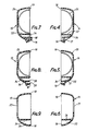
- Fig. 4 is a section on the line IV-IV of Fig. 2,
- Fig. 5 is a section on the line V-V of FIG. 2,
- Fig. 6 is a section on the line VI-VI of Fig. 2,
- Fig. 7 is a section on the line VII-VII of Fig. 3,
- Fig. 8 is a section on the line VIII-VIII of Fig. 3,
- Fig. 9 is a section on the line IX-IX of Fig. 3,
- Fig. 10 is an end view in the direction of arrow A in Fig. 2,
- Fig. 11 is an end view in the direction of arrow B in Fig. 3,
- Fig. 12 is a perspective view of a component,
- Fig. 13 is a transverse central cross section of the component,
- Fig. 14 is a scrap view showing the mounting of the component, and,
- Figs. 15 and 16 are explanatory schematic diagrams.
- The jig-saw shown in side elevation in Fig. 1 has a
housing 1 of two-part clam shell construction with ashoe 2 attached to the lower part of the housing. - The
housing 1 is formed to provide ahandle portion 3. Thehousing 1 accommodates an electric motor and a drive mechanism for reciprocating a saw blade drive shaft (not shown) to whose lower end a saw blade 4 is secured by means of areleasable clamp 5. The motor and drive mechanism are of conventional form. - Power is supplied to the motor via a
cable 6 and is controlled by a switch (not shown) operated by a trigger 7 with a 'lock-on' button 8. - Slidably mounted upon the front of the
housing 1 is a guard 9 of a transparent plastics material. The guard 9 occupies the position in which it is shown in Fig. 1 when the jig-saw is not in use. After a saw blade has been secured to the drive shaft by means of theclamp 5, the guard 9 is slid downwardly to a position in which the lower edges ofsmall projections 12 rest on the forward end of theshoe 2. On its inner face, the guard 9 has small projections indicated diagrammatically at 10 and 11 which co-operates with depressions in the surface of thehousing 1 to hold the guard in position. - When in its lowered position, the guard forms a protective shield around the front of the saw blade 4 without obscuring the user's view thereof. There is also a narrow gap left between the
lower edge 13 of the guard and the upper surface of theshoe 2 whose purpose will be described below. - The
housing 1 is formed from two housing parts of a suitable plastics material, 14 - Fig. 2 and 15 - Fig. 3, that are formed around their mating edges with co-operating steppedsurface 16 that engage when the parts are placed together. The parts are secured together by screws (not shown) that pass throughholes 17 inpart 14 and intobosses 18 located inpart 15 in positions corresponding with those of theholes 17. - The
parts space 19 for the motor and anadjacent space 20 for the mechanism for reciprocating the saw blade. - As is conventional in jig-saws, the armature shaft of the motor carries a fan which circulates air over the motor during use to cool the latter. The
housing parts air inlet slots outlet slots - Each
housing part ribs space 19 for supporting the motor andbosses space 20 for locating and supporting the mechanism for reciprocating the saw blade. A wall separates thespaces parts housing parts wall parts - The lower part of the
space 19 is bounded by a transverse wall formed byhalf walls housing parts suction passage 34 whose lower surface is, in part, the lower incurvedsurfaces housing parts wall parts wall parts recesses 39 in which locate nuts (not shown) which receive screws (not shown) which secure theshoe 2 to thehousing 1. - At its forward end adjacent the saw blade 4,
suction passage 34 joins a downwardlyinclined portion 40 formed betweenribs portion 40 terminates in an outlet adjacent the saw blade 4 in the vicinity of the work area thereof. As can be seen from Figs. 2 and 3, each housing part has a mountingadjacent rib 41 whose function will be described below. - At the other, rear end,
wall parts exit aperture 43 formed between theparts housing 1. Adjacent theaperture 43, theparts internal ribs ribs - A second
short passage 46 is formed above theportion 40 between theribs 41 andfurther ribs 47 of the housing parts. Thispassage 46 forms a "blow" passage and has a downward inclination similar to that ofportion 40 which it joins at its lower end. At its upper end,passage 46 terminates in the vicinity of the motor cooling fan and adjacent theexit slots - Positioned laterally across
portion 40 is aflow control valve 48 shown in perspective view in Fig. 12 and diagrammatically in Figs. 13 and 14. Thevalve 48 is of generally overall cylindrical form with astub axle 49 at one end and a lockingpeg 50 formed on asecond stub axle 49 at the other. Theaxle 49 is slotted as at 51 to enable a user to rotate the valve as will be described in more detail below. Between its ends, the valve is cut away as at 52 to form asemitubular sealing member 53. - The
valve 48 seats in the mountings referred to above and which are referenced 54 in Figs. 2 and 3. The mountings each comprise atubular socket 54 formed in the housing part and in which thestub axles 49 locate and adjacent end faces 55 which maintain the valve in a correct axial location.Socket 54 onhousing part 15 is cut away as at 56 to form end stops 57 that, in conjunction withpeg 50, limit the rotational movement of thevalve 48 to about 180° of arc. In addition, the cut away 56 ensures that the valve can be located in one orientation only - that in which thepeg 50 locates in the cut away. - Fig. 14 is a scrap view showing the
valve 48 mounted in the sockets. The joint face of thehousing halves body part 14 extends to the outer surface of that part to give access to theslot 51 thereby enabling a user to rotate the valve as required. - The
control valve 48 is rotatable between two extreme positions identified by the end stops 57. Firstly, the position shown in Fig. 15 in which thesemi-cylindrical portion 53 locates in theportion 40 and completely closes it, thepassage 46 being left completely open by the cut-away 52. The second position of thevalve 48 is shown in Fig. 16. Theportion 53 is now located in thepassage 46 completely closing it whilstportion 40 is left completely open by the cut-away 52. - Between those two positions of the
valve 48 either thepassage 46 is partially closed whilst theportion 40 remains fully closed or theportion 40 is partially closed and thepassage 46 remains fully closed. At no time during the rotation of thevalve 48 areportion 40 andpassage 46 simultaneously open either fully or partially. - Before using the jig saw, it is first necessary to fit the blade 4 and, if the user wishes to withdraw debris from the work area, to connect the short tube referred to above to a source of vacuum which may be a vacuum cleaner or a workshop cleaner for example.
- The
valve 48 then turns to the position shown in Fig. 16 in which passsage 46 is closed. - The jig-saw is then operated in the conventional manner and debris produced is entrained in the flow of air created along the
passage 34 from the work area. Air enters that area through the gap between thelower edges 13 of theguard 11 and the upper surface of theshoe 2 and round the vertical side of the guard. The air flow is shown in Fig. 16 by thearrows 59. - Surprisingly, such entrainment is found to be effective in the absence of the air blast on to the work area previously thought to assist such entrainment. The output of the motor cooling fan which would have entered
passage 46 had the latter not been closed is diverted, as indicated byarrows 60, out through theexit slots - If the user wishes to employ the jig saw without suction and to clear debris away from the work area by using the air blast, the vacuum source is disconnected and the
valve 48 rotates to the position shown in Fig. 15. Part of the output of the cooling fan can now enterpassage 46 and be directed thereby on to the work area. This is indicated in Fig. 15 by thearrows 61. - The effectiveness of the air blast is not affected by the simultaneous presence of suction.
- It will be appreciated that the control valve may take forms other than that described above. A slide valve may be used consisting of a simple component having a first position in which
passage 46 is closed . withportion 40 left open, and a second position in whichpassage 46 is left open andportion 40 closed. Alternatively, a flap type valve may be used. - Alternatively, the two valves may be separate and independently controllable so that movement of one does not affect the other. In that way, a user has complete control over the volume of air passing through the blow passage and over the degree of suction in the suction passage.
- In the embodiment described above with reference to the drawings, it is possible to dispense with suction merely by disconnecting the suction source. The use of the valve enables a user to terminate the air blast on to the work area when suction only is required.
- In the case in which the tool includes a second fan for creating air flow along the suction passage, a single valve in that passage will control the application of suction to the work area.
- The second fan may also be mounted upon the armature shaft of the motor. In that case, suction will always be present when the jig saw is in use but is prevented, when so required by the user, from being effective to draw debris away from the work area by the
valve 48 or its equivalent. - Furthermore, the
suction passage 34 may be external to the jig saw housing. It may be in the form of a separate conduit mounted upon the shoe for example and with its mouth located close to the work area and the exit of the blow passage to allow, if desired, the use of a single valve to control both suction and blow. Otherwise, separate valves may be used. - It is also possible to employ two valves one in the blow passage and the other in the suction passage, the valves may be interlocked in a manner that prevents them being operated to positions in which both passages are open simultaneously.
- In the embodiment described above, the blow and suction passages share a common outlet but are otherwise separate.
- In an alternative embodiment, the passages may merge into a single common passage whose outlet is located adjacent the
clamp 5 and in which thevalve 48 is located. The common passage could be a continuation of the blow or of the suction passage. - The invention may be embodied in hand-held power tools other than jig-saws, for example, routers, sabre saws and plaster saws, and sanders either belt or rotary.
- The invention is also applicable to bench mounted, i.e. stationary, tools.
Claims (18)
Applications Claiming Priority (2)
| Application Number | Priority Date | Filing Date | Title |
|---|---|---|---|
| GB858523854A GB8523854D0 (en) | 1985-09-27 | 1985-09-27 | Power tools |
| GB8523854 | 1985-09-27 |
Publications (2)
| Publication Number | Publication Date |
|---|---|
| EP0221652A1 EP0221652A1 (en) | 1987-05-13 |
| EP0221652B1 true EP0221652B1 (en) | 1990-02-28 |
Family
ID=10585808
Family Applications (1)
| Application Number | Title | Priority Date | Filing Date |
|---|---|---|---|
| EP86307006A Expired - Lifetime EP0221652B1 (en) | 1985-09-27 | 1986-09-11 | Improvements in or relating to power tools |
Country Status (3)
| Country | Link |
|---|---|
| EP (1) | EP0221652B1 (en) |
| DE (1) | DE3669123D1 (en) |
| GB (1) | GB8523854D0 (en) |
Families Citing this family (7)
| Publication number | Priority date | Publication date | Assignee | Title |
|---|---|---|---|---|
| DE8901092U1 (en) * | 1989-02-01 | 1989-03-30 | Hundegger, Hans, 8941 Hawangen | Device for chip removal on planing machines |
| DE19832005B4 (en) * | 1998-07-16 | 2011-08-11 | Robert Bosch GmbH, 70469 | Portable planer |
| JP4248766B2 (en) * | 2001-05-23 | 2009-04-02 | 株式会社マキタ | Reciprocating cutting tool |
| GB2399537A (en) | 2003-03-13 | 2004-09-22 | Black & Decker Inc | Method and apparatus for removing dust from a workpiece |
| DE102009054811B4 (en) * | 2009-12-17 | 2021-06-17 | Robert Bosch Gmbh | Hand machine tool |
| JP5526003B2 (en) | 2010-11-19 | 2014-06-18 | 株式会社マキタ | Cutting machine |
| DE102018218381B4 (en) * | 2018-10-26 | 2026-05-13 | Robert Bosch Gmbh | Hand-held power tool, in particular jigsaw with blower attachment |
Family Cites Families (4)
| Publication number | Priority date | Publication date | Assignee | Title |
|---|---|---|---|---|
| SE7309869L (en) * | 1973-07-13 | 1975-01-14 | Anders Henry Pettersson | DEVICE ON ONE TO A COMPRESSED AIR CELL CONNECTIBLE COMBINED SUCTION AND BLOWING NOZZLE. |
| US4051880A (en) * | 1976-10-29 | 1977-10-04 | The Singer Company | Dustless routers |
| DE8012652U1 (en) * | 1980-05-09 | 1982-01-28 | Scintilla Ag, Solothurn | Hand machine tool, in particular a jigsaw |
| FR2511925A1 (en) * | 1981-08-31 | 1983-03-04 | Peugeot Aciers Et Outillage | HAND TOOL MACHINE HAVING A CUTTING TOOL, ESPECIALLY A JIGSAW |
-
1985
- 1985-09-27 GB GB858523854A patent/GB8523854D0/en active Pending
-
1986
- 1986-09-11 DE DE8686307006T patent/DE3669123D1/en not_active Expired - Fee Related
- 1986-09-11 EP EP86307006A patent/EP0221652B1/en not_active Expired - Lifetime
Also Published As
| Publication number | Publication date |
|---|---|
| DE3669123D1 (en) | 1990-04-05 |
| EP0221652A1 (en) | 1987-05-13 |
| GB8523854D0 (en) | 1985-10-30 |
Similar Documents
| Publication | Publication Date | Title |
|---|---|---|
| US4414743A (en) | Circular saw | |
| US6981779B2 (en) | Power tools | |
| US6167626B1 (en) | Dust collection port for use with a saw | |
| EP1260299B1 (en) | Reciprocating cutting tools having devices for limiting scattering of cutting chips | |
| JP4733952B2 (en) | Cutting machine | |
| EP0810071B1 (en) | Viewing window for circular saw guard | |
| EP2908984B1 (en) | Outdoor power device internal cooling system | |
| US20090007441A1 (en) | Variable dust chute for circular saws | |
| GB2299051A (en) | Air assisted planer chip ejection | |
| US20050034782A1 (en) | Power tool | |
| US20050284543A1 (en) | Pre-directing insert for a bi-directional exhausting handheld planer | |
| CN111657780B (en) | Vertical dust collector | |
| EP0221652A1 (en) | Improvements in or relating to power tools | |
| WO2022044771A1 (en) | Work machine | |
| EP0818273A1 (en) | Pneumatic power tool | |
| US6173499B1 (en) | Vent cover for an electric saw | |
| CN111097963B (en) | Handheld machine tools, especially jigsaws | |
| EP1428614B1 (en) | Planer | |
| US7207874B2 (en) | Electric hand power tool | |
| CA2553395A1 (en) | Bevel quadrant and gearbox louver blower system | |
| EP4474091A1 (en) | Cut-off saw | |
| GB2111192A (en) | Power tools | |
| JP6938179B2 (en) | Desktop cutting machine | |
| US6810825B2 (en) | Wood planing machine with a shield member for a motor unit and a cutter member | |
| JP4498750B2 (en) | Circular saw |
Legal Events
| Date | Code | Title | Description |
|---|---|---|---|
| PUAI | Public reference made under article 153(3) epc to a published international application that has entered the european phase |
Free format text: ORIGINAL CODE: 0009012 |
|
| AK | Designated contracting states |
Kind code of ref document: A1 Designated state(s): DE FR GB |
|
| 17P | Request for examination filed |
Effective date: 19870701 |
|
| 17Q | First examination report despatched |
Effective date: 19881115 |
|
| GRAA | (expected) grant |
Free format text: ORIGINAL CODE: 0009210 |
|
| AK | Designated contracting states |
Kind code of ref document: B1 Designated state(s): DE FR GB |
|
| REF | Corresponds to: |
Ref document number: 3669123 Country of ref document: DE Date of ref document: 19900405 |
|
| ET | Fr: translation filed | ||
| PLBE | No opposition filed within time limit |
Free format text: ORIGINAL CODE: 0009261 |
|
| STAA | Information on the status of an ep patent application or granted ep patent |
Free format text: STATUS: NO OPPOSITION FILED WITHIN TIME LIMIT |
|
| 26N | No opposition filed | ||
| REG | Reference to a national code |
Ref country code: GB Ref legal event code: IF02 |
|
| PGFP | Annual fee paid to national office [announced via postgrant information from national office to epo] |
Ref country code: GB Payment date: 20040908 Year of fee payment: 19 |
|
| PGFP | Annual fee paid to national office [announced via postgrant information from national office to epo] |
Ref country code: FR Payment date: 20040920 Year of fee payment: 19 |
|
| PGFP | Annual fee paid to national office [announced via postgrant information from national office to epo] |
Ref country code: DE Payment date: 20041102 Year of fee payment: 19 |
|
| PG25 | Lapsed in a contracting state [announced via postgrant information from national office to epo] |
Ref country code: GB Free format text: LAPSE BECAUSE OF NON-PAYMENT OF DUE FEES Effective date: 20050911 |
|
| PG25 | Lapsed in a contracting state [announced via postgrant information from national office to epo] |
Ref country code: DE Free format text: LAPSE BECAUSE OF NON-PAYMENT OF DUE FEES Effective date: 20060401 |
|
| GBPC | Gb: european patent ceased through non-payment of renewal fee |
Effective date: 20050911 |
|
| PG25 | Lapsed in a contracting state [announced via postgrant information from national office to epo] |
Ref country code: FR Free format text: LAPSE BECAUSE OF NON-PAYMENT OF DUE FEES Effective date: 20060531 |
|
| REG | Reference to a national code |
Ref country code: FR Ref legal event code: ST Effective date: 20060531 |