EP0220437B1 - Generator for producing binary cipher sequences - Google Patents
Generator for producing binary cipher sequences Download PDFInfo
- Publication number
- EP0220437B1 EP0220437B1 EP86112345A EP86112345A EP0220437B1 EP 0220437 B1 EP0220437 B1 EP 0220437B1 EP 86112345 A EP86112345 A EP 86112345A EP 86112345 A EP86112345 A EP 86112345A EP 0220437 B1 EP0220437 B1 EP 0220437B1
- Authority
- EP
- European Patent Office
- Prior art keywords
- generator
- generators
- sequences
- sequence
- period
- Prior art date
- Legal status (The legal status is an assumption and is not a legal conclusion. Google has not performed a legal analysis and makes no representation as to the accuracy of the status listed.)
- Expired - Lifetime
Links
Images
Classifications
-
- H—ELECTRICITY
- H03—ELECTRONIC CIRCUITRY
- H03K—PULSE TECHNIQUE
- H03K3/00—Circuits for generating electric pulses; Monostable, bistable or multistable circuits
- H03K3/84—Generating pulses having a predetermined statistical distribution of a parameter, e.g. random pulse generators
-
- H—ELECTRICITY
- H04—ELECTRIC COMMUNICATION TECHNIQUE
- H04L—TRANSMISSION OF DIGITAL INFORMATION, e.g. TELEGRAPHIC COMMUNICATION
- H04L9/00—Cryptographic mechanisms or cryptographic arrangements for secret or secure communications; Network security protocols
- H04L9/06—Cryptographic mechanisms or cryptographic arrangements for secret or secure communications; Network security protocols the encryption apparatus using shift registers or memories for block-wise or stream coding, e.g. DES systems or RC4; Hash functions; Pseudorandom sequence generators
- H04L9/065—Encryption by serially and continuously modifying data stream elements, e.g. stream cipher systems, RC4, SEAL or A5/3
- H04L9/0656—Pseudorandom key sequence combined element-for-element with data sequence, e.g. one-time-pad [OTP] or Vernam's cipher
- H04L9/0662—Pseudorandom key sequence combined element-for-element with data sequence, e.g. one-time-pad [OTP] or Vernam's cipher with particular pseudorandom sequence generator
Definitions
- the invention relates to a generator for generating binary encryption sequences according to the preamble of patent claim 1.
- Such generators are used in particular for the encryption of binary coded speech, as well as binary messages and data.
- Binary sequences are often encrypted by mixing them with a "pseudo-random" cipher sequence.
- these are generated by finite deterministic generators and are therefore necessarily periodic.
- the generators themselves are designed so that some settings can be freely selected and used as a key. It is now assumed that this key is the only secret element on such a generator. Accordingly, it is desirable that different keys lead to very different encryption sequences.
- stream ciphering a corresponding element of a binary cipher sequence modulo 2 is added to each element of a binary sequence.
- the encryption sequence generated with a given key is accessible to everyone. It is therefore essential that the law of formation of the sequence is not easy to guess. If the cipher sequence is unbalanced, statistical analysis can also be used to reconstruct part of the sequence that carries the message. Therefore, the encryption sequence statistics must be balanced, i.e. The cipher sequence must not differ significantly in terms of its statistics from a sequence that is created by ideally tossing an ideal coin.
- a cipher generator with several subgenerators is also known from document DE-A-24 51711. These are located on different hierarchical levels, with several subgenerators running in parallel at a certain level. The data outputs of a stage are linked together and passed on as input data to the subsequent generators.
- the shift registers, which act as partial generators, are all controlled by an external clock generator.
- the invention solves the problem of specifying a generator of the type mentioned, for which not only the quantities defined under 1) to 5) can be calculated, but also their associated conditions are all met.
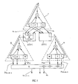
- ⁇ , ⁇ and ⁇ 1 three partial generators, shown schematically as dashed triangles, are designated, which binary sequences K , ⁇ and ⁇ with a period of K, M and M.
- K 2 k-1
- M 2 m-1
- M 2 m -1
- the length k, m and m can be implemented.
- part or all of the bits of the shift register, added to one another, for example, modulo-2, are fed back to its input.
- the subgenerators ⁇ , ⁇ and ⁇ must be clocked and each have clock inputs c.
- the partial generator r receives its clock from an external clock generator (not shown in FIG. 1).
- the clocks of the two other subgenerators ⁇ and ⁇ are derived from outputs of the partial generator r via function transmitters ⁇ f (t) and ⁇ f (t).
- the sequence K should be able to be tapped at each of these outputs, specifically at a different time position (phase) at each output. With a length K of the period of the sequence K , K such different temporal positions Kt ... K t- (K-1) are possible in principle.
- the sequences ⁇ and ⁇ can of the partial generators ⁇ and ⁇ are generated in different temporal positions.
- the M or m different temporal positions can in turn be realized by suitable linear combinations of only m or m successive outputs of the shift register. Therefore, only m or M of such outputs are shown in FIG. 1.
- the at the outputs of the subgenerators ⁇ and ⁇ Available sequences are, not necessarily all, linked via at least one linking unit X to the cipher sequence w t , which may also be available in different temporal positions w t , ..., ⁇ t- (T-1) .
- the elements described are the three subgenerators ⁇ , ⁇ and ⁇ , the two function transmitters ⁇ f (t) and ⁇ f (t) and the combination unit X in their combination form a generator according to the invention.
- the function generator ⁇ f (t) can, for example, forward the sequence K alone in the time position t to the clock input c of the subgenerator ⁇ , while by the function generator ⁇ f (t) for example, the complement of the sequence K in the time position t and modulo-2 added to the product of the sequence K in all time positions, that is modulo-2 to K t- (k-1) ... K t-1 K t adds to the clock input c of the sub-generator ⁇ can be led.
- the linking unit X allows certain temporal positions of the subgenerators ⁇ and ⁇ generated sequences ⁇ and ⁇ be modulo-2 added, which for the ⁇ f (t) , ... ⁇ f (t) - (m-1 ) in FIG. 1 is also shown, for example, within the rectangle forming the linking unit X.
- the generator according to the invention has the properties explained below with regard to the sizes and conditions defined at 1) to 5):
- the subgenerators ⁇ , ⁇ and ⁇ 1 need not necessarily be implemented by linear feedback shift registers. Any other implementations are also possible.
- a generator of the type described can also be used as a partial generator in the sense of cascading.
- K, ⁇ (1) , ..., ⁇ (n) are sequences of the periods K, M (1) , ..., M (n) which are generated by n + 1 arbitrary subgenerators r, ⁇ (1), ⁇ (n) are generated and if ⁇ f (1) , ..., ⁇ f (n) are arbitrary K-periodic functions of K and t, the sequence generated by the composite generator is complete given, where f (i) (t) by was defined.
Description
Die Erfindung betrifft einen Generator zur Erzeugung binärer Chiffriersequenzen gemäss dem Oberbegriff des Patentanspruchs 1.The invention relates to a generator for generating binary encryption sequences according to the preamble of
Solche Generatoren werden insbesondere zur Verschlüsselung von binär codierter Sprache, sowie von binären Nachrichten und Daten eingegesetzt. Binäre Sequenzen werden häufig dadurch verschlüsselt, dass sie mit einer "pseudozufälligen" Chiffriersequenz vermischt werden. Diese werden per definitionem durch endliche deterministische Generatoren erzeugt und sind damit zwangsläufig periodisch. Die Generatoren selbst werden so ausgelegt, dass einige Einstellungen frei wählbar sind und als Schlüssel verwendet werden können. Man geht heute davon aus, dass dieser Schlüssel das einzige geheime Element an einem solchen Generator ist. Entsprechend ist es wünschenswert, dass verschiedene Schlüssel zu stark verschiedenen Chiffriersequenzen führen.Such generators are used in particular for the encryption of binary coded speech, as well as binary messages and data. Binary sequences are often encrypted by mixing them with a "pseudo-random" cipher sequence. By definition, these are generated by finite deterministic generators and are therefore necessarily periodic. The generators themselves are designed so that some settings can be freely selected and used as a key. It is now assumed that this key is the only secret element on such a generator. Accordingly, it is desirable that different keys lead to very different encryption sequences.
Beim sogenannten "stream ciphering" wird zu jedem Element einer binären Sequenz ein entsprechendes Element einer binären Chiffriersequenz modulo 2 hinzuaddiert. Bei diesem einfachen Verfahren muss damit gerechnet werden, dass die mit einem gegebenen Schlüssel erzeugte Chiffriersequenz jedermann zugänglich ist. Es ist deshalb wesentlich, dass das Bildungsgesetz der Sequenz nicht leicht zu erraten ist. Bei unausgeglichener Statistik der Chiffriersequenz kann man ferner durch statistische Analysen einen Teil der die Botschaft tragenden Sequenz rekonstruieren. Deshalb muss die Statistik der Chiffriersequenz ausgeglichen sein, d.h. die Chiffriersequenz darf sich in Bezug auf ihre Statistik nicht wesentlich von einer Sequenz unterscheiden, die durch ideales Werfen einer idealen Münze entsteht.In so-called "stream ciphering", a corresponding element of a binary
Ein Generator der eingangs genannten Art wurde in den folgenden Veröffentlichungen untersucht:
- W. G. Chambers and S. M. Jennings, "Linear equivalence of certain BRM shiftregister sequences", Electronics Letters, vol. 20, pp. 1018-1019, Nov. 1984.
- K. Kjeldsen and E. Andresen, "Some randomness properties of cascaded sequences", IEEE Trans. Inform. Theory, vol. IT-26, pp. 227-232, March 1980.
- B. Smeets, "On the autocorrelation function of some sequences generated by clock controlled shift registers", Proceedings of the Second Joint Swedish-Soviet Intern. Workshop on Inform. Theory, pp. 130-136 (1985).
- R. Vogel, "On the Linear Complexity of Cascaded Sequences", Adv. in Cryptology - EUROCRYPT'84, Lecture Notes in Computer Science, Vol. 209, p. 99-109, Springer Verlag 1985.
- WG Chambers and SM Jennings, "Linear equivalence of certain BRM shift register sequences", Electronics Letters, vol. 20, pp. 1018-1019, Nov. 1984.
- K. Kjeldsen and E. Andresen, "Some randomness properties of cascaded sequences", IEEE Trans. Inform. Theory, vol. IT-26, pp. 227-232, March 1980.
- B. Smeets, "On the autocorrelation function of some sequences generated by clock controlled shift registers", Proceedings of the Second Joint Swedish-Soviet Intern. Workshop on Inform. Theory, pp. 130-136 (1985).
- R. Vogel, "On the Linear Complexity of Cascaded Sequences", Adv. In Cryptology - EUROCRYPT'84, Lecture Notes in Computer Science, Vol. 209, p. 99-109, Springer Verlag 1985.
Aus der Patentschrift DE-C-977 715 ist ein aus mehreren Teilgeneratoren bestehender Zufallsgenerator bekannt. Die einzelnen Teilgeneratoren sind linear rückgekoppelte Schieberegister, die mit Abtast- und Antriebsorganen versehen sind. Sie sind derart in Serie geschaltet, dass ein Ausgang eines bestimmten Schieberegisters in Verbindung mit einem externen Signal auf das Antriebsorgan aller nachfolgender Schieberegister einwirkt. Die Impulse der Ableseorgane werden modulo-2 verknüpft und an einer Klemme ausgegeben.From the patent DE-C-977 715 a random generator consisting of several partial generators is known. The individual subgenerators are linear feedback shift registers which are provided with scanning and drive elements. They are connected in series in such a way that an output of a specific shift register in conjunction with an external signal acts on the drive element of all subsequent shift registers. The pulses from the reading organs are linked modulo-2 and output at a terminal.
Ans der Schrift DE-A-24 51711 ist ebenfalls ein Chiffriergenerator mit mehreren Teilgeneratoren bekannt. Diese sind auf verschiedenen Hierarchiestufen untergebracht, wobei auf einer bestimmten Stufe jeweils mehrere Teilgeneratoren parallel laufen. Die Datenausgänge einer Stufe werden miteinander verknüpft und als Eingangsdaten an die nachfolgenden Generatoren weitergegeben. Die als Teilgeneratoren wirkenden Schieberegister werden alle von einem externen Taktgeber gesteuert.A cipher generator with several subgenerators is also known from document DE-A-24 51711. These are located on different hierarchical levels, with several subgenerators running in parallel at a certain level. The data outputs of a stage are linked together and passed on as input data to the subsequent generators. The shift registers, which act as partial generators, are all controlled by an external clock generator.
Im folgenden werden nun einige für die Beurteilung der Generatoreigenschaften wichtige Grössen eingeführt. Diese lauten zusammen mit den notwendigen Bedingungen, welche sich für diese Grössen ergeben, wie folgt:
- 1) Periode: Unter der Periode T(w) einer Sequenz w verstehen wir die minimale Periode dieser Sequenz, das ist die kleinste Zahl T, so dass

- 2) Lineare Komplexität: Die lineare Komplexität L(w) einer Sequenz w ist die Länge des kürzesten linear rückgekoppelten Schieberegisters das die Sequenz w erzeugt. Bemerkung: Die Kenntnis der Sequenz in 2L (w) aufeinanderfolgenden Zeitpunkten erlaubt ihre vollständige Bestimmung durch Anwendung des sogenannten Massey-Algorithmus. Bedingung: Die lineare Komplexität einer Chiffriersequenz muss gross sein.
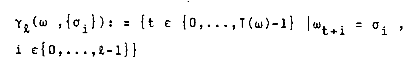
- 3) Häufigkeit von Konfigurationen kleiner Länge: (Poker-Test) Die Häufigkeit γ(ω, {σi}) der Konfiguration {σi}I-1 o der Länge I in w ist definiert durch:
- - Für eine periodisch fortgesetzte Folge statistisch unabhängiger gleichverteilter Zufallsvariablen gilt:

- - Fur eine Chiffriersequenz kann dies i.A. nicht gelten, z.B. kommt bis auf zyklische Vertauschungen nur eine einzige Konfiguration der Länge T vor. Für eine solche Sequenz kann die Aussage aber noch für I ≦ I* gelten, wobei I* von der Grössenordnung log2T ist. Mit dieser Einschränkung muss sie sogar gelten, da sonst statistische Analysen möglich werden.
- Bedingung: Für eine Chiffriersequenz w muss mit einem "gross genügendem" 1*(w) gelten:


- Bedingung: Für eine Chiffriersequenz w muss mit einem "gross genügendem" 1*(w) gelten:
- - Für eine periodisch fortgesetzte Folge statistisch unabhängiger gleichverteilter Zufallsvariablen gilt:
- 4) 2-Punkt-Autokorrelationen:
- Die 2-Punkt-Autokorrelationen Cω(τ) der Sequenz w sind definiert durch:

- Sie liefern ein Mass für den Uebereinstimmungsgrad einer Sequenz mit ihren zyklischen Permutationen.
- Bedingung: Schränkt man τ auf {0, ... , T-1} ein, so muss für eine Chiffriersequenz w der Periode T für fast alle τ gelten:
- Die 2-Punkt-Autokorrelationen Cω(τ) der Sequenz w sind definiert durch:
-

- 5) 2-Punkt-Kreuzkorrelationen zwischen zwei Sequenzen ω(1) und ω(2) die mit zwei verschiedenen Schlüsseln S(1) und S(2) erzeugt wurden:
- Diese Grössen sind definiert durch

- Sie bilden ein Mass für die Schlüsselabhängigkeit der erzeugten Sequenzen.
- Bedingung: Sind ω(1) und ω(2) zwei Chiffriersequenzen die durch einen gegebenen Generator mit verschiedenen Schlüsseleinstellungen S(1) und S(2) erzeugt wurden, so muss für fast alle T ε{0, ... , T-1 gelten:
- Diese Grössen sind definiert durch
- 1) Period: The period T (w) of a sequence w means the minimum period of this sequence, that is the smallest number T, so that
- 2) Linear complexity: The linear complexity L (w) of a sequence w is the length of the shortest linear feedback shift register that generates the sequence w. Note: Knowing the sequence in 2L (w) consecutive times allows its complete determination by using the so-called Massey algorithm. Condition: The linear complexity of a cipher sequence must be great.
- 3) Frequency of configurations of short length: (Poker test) The frequency γ (ω, {σ i }) of the configuration {σ i } I-1 o of length I in w is defined by:
- - For a periodically continued sequence of statistically independent, equally distributed random variables:
- - This cannot generally apply to a cipher sequence, for example, apart from cyclical interchanges, there is only one configuration of length T. For such a sequence, however, the statement can still apply to I ≦ I *, where I * is of the order of log 2 T. With this limitation, it must even apply, otherwise statistical analyzes are possible.
- Condition: For a cipher sequence w the following must apply with a "large enough" 1 * (w):
- Condition: For a cipher sequence w the following must apply with a "large enough" 1 * (w):
- - For a periodically continued sequence of statistically independent, equally distributed random variables:
- 4) 2-point autocorrelations:
- The 2-point autocorrelations C ω (τ) of the sequence w are defined by:
- They provide a measure of the degree of agreement of a sequence with its cyclic permutations.
- Condition: If τ is restricted to {0, ..., T-1}, then for a cipher sequence w of period T the following must apply to almost all τ:
- The 2-point autocorrelations C ω (τ) of the sequence w are defined by:
-
- 5) 2-point cross-correlations between two sequences ω (1) and ω (2) with two different keys S (1) and S (2) were produced:
- These sizes are defined by
- They form a measure of the key dependency of the sequences generated.
- Condition: If ω (1) and ω (2) are two cipher sequences generated by a given generator with different key settings S (1) and S (2) , then for almost all T ε {0, ..., T- 1 apply:
- These sizes are defined by
![]()
![]()
Bei dem bekannten Generator sind die unter 1) und 2) genannten Bedingungen erfüllt. Weiter sind bei dem bekannten Generator die unter 3) und 4) definierten Grössen zwar berechenbar, die zugehörigen Bedingungen jedoch nicht erfüllt.In the known generator, the conditions mentioned under 1) and 2) are met. Furthermore, the variables defined under 3) and 4) can be calculated in the known generator, but the associated conditions are not met.
Die Erfindung, wie sie in den Patentansprüchen gekennzeichnet ist, löst die Aufgabe, einen Generator der eingangs genannten Art anzugeben, für den nicht nur die unter 1) bis 5) definierten Grössen berechenbar, sondern zudem ihre zugehörigen Bedingungen sämtlich erfüllt sind.The invention, as characterized in the claims, solves the problem of specifying a generator of the type mentioned, for which not only the quantities defined under 1) to 5) can be calculated, but also their associated conditions are all met.
Die durch die Erfindung erreichten Vorteile sind im wesentlichen darin zu sehen, dass neben der Tatsache, dass der erfindungsgemässe Generator hervorragende Eigenschaften im Sinne der unter 1) bis 5) genannten Bedingungen aufweist, er darüber hinaus äusserst einfach zu implementieren ist.The advantages achieved by the invention can essentially be seen in the fact that, in addition to the fact that the generator according to the invention has excellent properties in the sense of the conditions mentioned under 1) to 5), it is also extremely easy to implement.
Im folgenden wird die Erfindung anhand von Ausführungsbeispielen näher erläutert, wobei auf die Zeichnung Bezug genommen wird. Es zeigt:
- Fig. 1 einen Generator, welcher unter Verwendung von drei Teilgeneratoren aufgebaut ist und
- Fig. 2 einen Generator, welcher sich durch Verallgemeinerung des Generators nach Fig. 1 ergibt.
- Fig. 1 shows a generator, which is constructed using three sub-generators and
- Fig. 2 shows a generator, which results from generalization of the generator of FIG. 1.
Mit Γ,ψ und
Die drei Teilgeneratoren Γ, ψ und
Die Teilgeneratoren Γ, ψ und
Auch die Sequenzen µ und
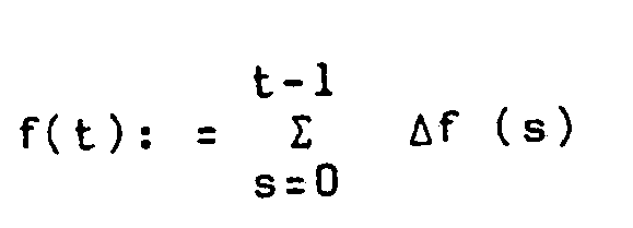
Die Funktionen f und f sind definiert durchThe functions f and f are defined by

Die an den Ausgängen der Teilgeneratoren ψ und
Die beschriebenen Elemente, das sind die drei Teilgeneratoren Γ, ψ und
Wie in Fig. 1 innerhalb der die Funktionsgeber Δf(t) und Δf(t) darstellenden Rechtecke gezeigt, kann durch den Funktionsgeber Δf(t) beispielsweise die Sequenz K allein in der zeitlichen Lage t an den Takteingang c des Teilgenerators ψ weitergegeben sein, während durch den Funktionsgeber Δ
Mit den vorgenannten speziellen Ausbildungen der Teilgeneratoren r, ψ und
Es seien:

![]()
![]()
- (Φ und
Φ sind Schlüssel, welche die Phase zwischen den Teilgeneratoren Γ und ψ einerseits und rundψ andererseits festlegen), dann definiert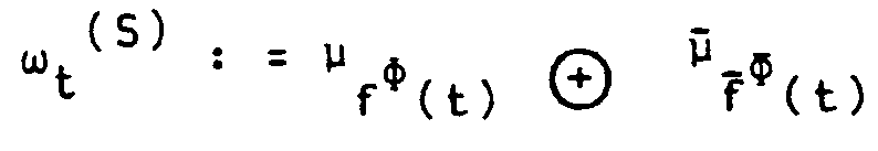
φ ).
- (Φ and
Φ are keys that round the phase between the partial generators Γ and ψ on the one handψ on the other hand), then definedφ ).
Im oben beschriebenen Fall, d.h. wenn r, ψ, ![]()
![]()
- 1. für die Periode

- 2. für die lineare Komplexität:

- 3a. für die relative Häufigkeit von "1":
- 3b. für die relative Häufigkeit von Konfigurationen einer Länge I ≦ min (k,m,m):

- 1. for the period
- 2. for linear complexity:
- 3a. for the relative frequency of "1":
- 3b. for the relative frequency of configurations with a length I ≦ min (k, m, m):
Hier, wie auch im folgenden, soll 0( ... ) so verstanden sein, dass
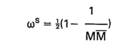
- 4. für die 2-Punkt-Autokorrelationen:


- 5. für die 2-Punkt-Kreuzkorrelationen zwischen zwei Sequenzen die
mit 2 verschiedenen Schlüsseln S(1) und S(2) erzeugt werden:


- 4. for the 2-point autocorrelations:
- 5. for the 2-point cross correlations between two sequences that are generated with 2 different keys S (1) and S (2) :
Diese Ergebnisse, welche für realistische Wahlen der Parameter (z.B. k = m = 127, m = 255) hervorragende Eigenschaften im Sinn von 1) bis 5) garantieren, zusammen mit der äusserst einfachen Implementierung, prädestinieren die beschriebene Struktur für kryptographische Anwendungen.These results, which guarantee excellent properties in the sense of 1) to 5) for realistic selection of the parameters (e.g. k = m = 127, m = 255), together with the extremely simple implementation, predestine the structure described for cryptographic applications.
Die Teilgeneratoren Γ, ψ und
Sind K, µ, ![]()
![]()

![]()
![]()
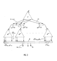
Eine Verallgemeinerung des bisher beschriebenen und in Fig. 1 dargestellten Generators ergibt sich weiter indem man an Stelle von 3 beliebigen Teilgeneratoren n+1 beliebige Teilgeneratoren in entsprechender Weise verknüpft, wie dies in Fig. 2 dargestellt ist. D.h. sind K, µ(1), ..., µ(n) Sequenzen der Perioden K, M(1),..., M(n) die durch n+1 beliebige Teilgeneratoren r, ψ(1), ψ(n) erzeugt werden und sind Δf(1),..., Δf(n) beliebige K-periodische Funktionen von K und t, so ist die durch den zusammengesetzten Generator erzeugte Sequenz durch

Schliesslich können im Beispiel von Fig. 1 wie im Beispiel von Fig. 2 die von den Teilgeneratoren ψ und 

Claims (8)
Applications Claiming Priority (2)
| Application Number | Priority Date | Filing Date | Title |
|---|---|---|---|
| CH4482/85 | 1985-10-17 | ||
| CH4482/85A CH668340A5 (en) | 1985-10-17 | 1985-10-17 | GENERATOR FOR GENERATING BINARY CIFFERENTIAL SEQUENCES. |
Publications (2)
| Publication Number | Publication Date |
|---|---|
| EP0220437A1 EP0220437A1 (en) | 1987-05-06 |
| EP0220437B1 true EP0220437B1 (en) | 1990-06-06 |
Family
ID=4276924
Family Applications (1)
| Application Number | Title | Priority Date | Filing Date |
|---|---|---|---|
| EP86112345A Expired - Lifetime EP0220437B1 (en) | 1985-10-17 | 1986-09-06 | Generator for producing binary cipher sequences |
Country Status (4)
| Country | Link |
|---|---|
| US (1) | US4817145A (en) |
| EP (1) | EP0220437B1 (en) |
| CH (1) | CH668340A5 (en) |
| DE (1) | DE3671817D1 (en) |
Families Citing this family (8)
| Publication number | Priority date | Publication date | Assignee | Title |
|---|---|---|---|---|
| US5363448A (en) * | 1993-06-30 | 1994-11-08 | United Technologies Automotive, Inc. | Pseudorandom number generation and cryptographic authentication |
| US5608801A (en) * | 1995-11-16 | 1997-03-04 | Bell Communications Research, Inc. | Efficient cryptographic hash functions and methods for amplifying the security of hash functions and pseudo-random functions |
| US6009135A (en) * | 1997-10-10 | 1999-12-28 | Interdigtal Technology Corporation | Method and apparatus for generating a stream cipher |
| DE19757370C2 (en) * | 1997-12-22 | 2000-03-23 | Siemens Ag | Process for the tactile generation of pseudo-random data words |
| EP1111785A1 (en) * | 1999-12-22 | 2001-06-27 | TELEFONAKTIEBOLAGET L M ERICSSON (publ) | Method and device for self-clock controlled pseudo random noise (PN) sequence generation |
| US6522210B1 (en) * | 2000-02-16 | 2003-02-18 | Honeywell International Inc. | Random pulse generator |
| GB0123302D0 (en) * | 2001-09-28 | 2001-11-21 | Hw Comm Ltd | Cipher apparatus |
| US8121292B2 (en) * | 2002-02-26 | 2012-02-21 | Qualcomm Incorporated | Method and apparatus for scrambling information bits on a channel in a communications system |
Family Cites Families (10)
| Publication number | Priority date | Publication date | Assignee | Title |
|---|---|---|---|---|
| DE977715C (en) * | 1962-05-18 | 1968-08-29 | Philips Usfa Nv | Encryption device |
| US3548174A (en) * | 1966-08-10 | 1970-12-15 | Burroughs Corp | Random number generator |
| US3728529A (en) * | 1969-10-08 | 1973-04-17 | Sperry Rand Corp | Two-way communication system employing two-clock frequency pseudo-noise signal modulation |
| US3986168A (en) * | 1975-06-02 | 1976-10-12 | Ncr Corporation | Multichannel error signal generator |
| US4115657A (en) * | 1976-11-11 | 1978-09-19 | Datotek, Inc. | Random digital code generator |
| US4202051A (en) * | 1977-10-03 | 1980-05-06 | Wisconsin Alumni Research Foundation | Digital data enciphering and deciphering circuit and method |
| US4161041A (en) * | 1978-10-06 | 1979-07-10 | The United States Of America As Represented By The Secretary Of The Air Force | Pseudo random number generator apparatus |
| US4375620A (en) * | 1980-12-15 | 1983-03-01 | The United States Of America As Represented By The Secretary Of The Navy | Pseudo-atmospheric noise generator with control of temporal characteristics |
| JPS57194621A (en) * | 1981-05-26 | 1982-11-30 | Nec Corp | Random number generator |
| GB2178535B (en) * | 1985-07-27 | 1988-11-09 | Rolls Royce | Digital noise generator |
-
1985
- 1985-10-17 CH CH4482/85A patent/CH668340A5/en not_active IP Right Cessation
-
1986
- 1986-09-06 DE DE8686112345T patent/DE3671817D1/en not_active Expired - Fee Related
- 1986-09-06 EP EP86112345A patent/EP0220437B1/en not_active Expired - Lifetime
- 1986-10-15 US US06/918,884 patent/US4817145A/en not_active Expired - Fee Related
Also Published As
| Publication number | Publication date |
|---|---|
| CH668340A5 (en) | 1988-12-15 |
| EP0220437A1 (en) | 1987-05-06 |
| US4817145A (en) | 1989-03-28 |
| DE3671817D1 (en) | 1990-07-12 |
Similar Documents
| Publication | Publication Date | Title |
|---|---|---|
| DE19744961B4 (en) | Generate unique and unpredictable values | |
| DE1537062C3 (en) | Key generator | |
| DE69929251T2 (en) | ENCRYPTION SYSTEM WITH A KEY OF CHANGING LENGTH | |
| DE19827904C2 (en) | Block cipher or decipher method and block cipher or decipher device | |
| EP0012974B1 (en) | Method for enciphering data blocks of a given length | |
| EP0482154A1 (en) | Device for converting a digital block and the use thereof. | |
| DE112011106024B4 (en) | Device specific information generating apparatus and device specific information generating method | |
| DE1512617B1 (en) | Circuit arrangement for generating a pulse code from an incoming pulse train | |
| DE10339999B4 (en) | Pseudorandom number generator | |
| EP0220437B1 (en) | Generator for producing binary cipher sequences | |
| DE69333257T2 (en) | System for signal switching and processing | |
| DE10347455B4 (en) | Pseudo-random number generator for a stream cipher | |
| EP0189734B1 (en) | Method and apparatus for converting a digital data sequence into an enciphered form | |
| EP0002478B1 (en) | Cryptographic apparatus | |
| DE60004409T2 (en) | Circuit and method for generating random numbers | |
| DE19757370C2 (en) | Process for the tactile generation of pseudo-random data words | |
| WO2001013218A1 (en) | Method for generating pseudo random numbers and method for electronic signatures | |
| DE2058796C3 (en) | Method and device for the synchronization of random character generators | |
| WO2000054406A1 (en) | Random signal generator and method for generating a random signals | |
| EP0146865B1 (en) | Method of generating pseudo-random trains of binary signals | |
| DE60119254T2 (en) | Arithmetic unit for determining the inverse of an integer modulus of a large number | |
| DE1188123B (en) | Electronic encryptor with an arrangement that delivers each plaintext letter to be encrypted in the form of a group of binary signals | |
| DE10206065A1 (en) | Symmetrical encryption of message, by determining which datum of key that is marked with pointer is linked with retrieved datum of message | |
| DE59100171C5 (en) | DEVICE FOR CONVERTING A DIGITAL BLOCK AND USE THEREOF. | |
| DE1512617C (en) |
Legal Events
| Date | Code | Title | Description |
|---|---|---|---|
| PUAI | Public reference made under article 153(3) epc to a published international application that has entered the european phase |
Free format text: ORIGINAL CODE: 0009012 |
|
| AK | Designated contracting states |
Kind code of ref document: A1 Designated state(s): CH DE GB LI SE |
|
| RAP1 | Party data changed (applicant data changed or rights of an application transferred) |
Owner name: BBC BROWN BOVERI AG |
|
| 17P | Request for examination filed |
Effective date: 19870917 |
|
| 17Q | First examination report despatched |
Effective date: 19890406 |
|
| GRAA | (expected) grant |
Free format text: ORIGINAL CODE: 0009210 |
|
| AK | Designated contracting states |
Kind code of ref document: B1 Designated state(s): CH DE GB LI SE |
|
| REF | Corresponds to: |
Ref document number: 3671817 Country of ref document: DE Date of ref document: 19900712 |
|
| GBT | Gb: translation of ep patent filed (gb section 77(6)(a)/1977) | ||
| PLBE | No opposition filed within time limit |
Free format text: ORIGINAL CODE: 0009261 |
|
| STAA | Information on the status of an ep patent application or granted ep patent |
Free format text: STATUS: NO OPPOSITION FILED WITHIN TIME LIMIT |
|
| 26N | No opposition filed | ||
| EAL | Se: european patent in force in sweden |
Ref document number: 86112345.3 |
|
| PGFP | Annual fee paid to national office [announced via postgrant information from national office to epo] |
Ref country code: CH Payment date: 19990813 Year of fee payment: 14 |
|
| PGFP | Annual fee paid to national office [announced via postgrant information from national office to epo] |
Ref country code: SE Payment date: 19990816 Year of fee payment: 14 |
|
| PGFP | Annual fee paid to national office [announced via postgrant information from national office to epo] |
Ref country code: GB Payment date: 19990818 Year of fee payment: 14 |
|
| PGFP | Annual fee paid to national office [announced via postgrant information from national office to epo] |
Ref country code: DE Payment date: 19990825 Year of fee payment: 14 |
|
| PG25 | Lapsed in a contracting state [announced via postgrant information from national office to epo] |
Ref country code: GB Free format text: LAPSE BECAUSE OF NON-PAYMENT OF DUE FEES Effective date: 20000906 |
|
| PG25 | Lapsed in a contracting state [announced via postgrant information from national office to epo] |
Ref country code: SE Free format text: THE PATENT HAS BEEN ANNULLED BY A DECISION OF A NATIONAL AUTHORITY Effective date: 20000929 |
|
| PG25 | Lapsed in a contracting state [announced via postgrant information from national office to epo] |
Ref country code: LI Free format text: LAPSE BECAUSE OF NON-PAYMENT OF DUE FEES Effective date: 20000930 Ref country code: CH Free format text: LAPSE BECAUSE OF NON-PAYMENT OF DUE FEES Effective date: 20000930 |
|
| GBPC | Gb: european patent ceased through non-payment of renewal fee |
Effective date: 20000906 |
|
| REG | Reference to a national code |
Ref country code: CH Ref legal event code: PL |
|
| EUG | Se: european patent has lapsed |
Ref document number: 86112345.3 |
|
| PG25 | Lapsed in a contracting state [announced via postgrant information from national office to epo] |
Ref country code: DE Free format text: LAPSE BECAUSE OF NON-PAYMENT OF DUE FEES Effective date: 20010601 |