EP0219800A2 - Mixing device for liquids - Google Patents
Mixing device for liquids Download PDFInfo
- Publication number
- EP0219800A2 EP0219800A2 EP86114192A EP86114192A EP0219800A2 EP 0219800 A2 EP0219800 A2 EP 0219800A2 EP 86114192 A EP86114192 A EP 86114192A EP 86114192 A EP86114192 A EP 86114192A EP 0219800 A2 EP0219800 A2 EP 0219800A2
- Authority
- EP
- European Patent Office
- Prior art keywords
- line
- liquid
- pressure
- inlet
- outlet
- Prior art date
- Legal status (The legal status is an assumption and is not a legal conclusion. Google has not performed a legal analysis and makes no representation as to the accuracy of the status listed.)
- Withdrawn
Links
Images


Classifications
-
- B—PERFORMING OPERATIONS; TRANSPORTING
- B01—PHYSICAL OR CHEMICAL PROCESSES OR APPARATUS IN GENERAL
- B01F—MIXING, e.g. DISSOLVING, EMULSIFYING OR DISPERSING
- B01F23/00—Mixing according to the phases to be mixed, e.g. dispersing or emulsifying
- B01F23/40—Mixing liquids with liquids; Emulsifying
- B01F23/49—Mixing systems, i.e. flow charts or diagrams
-
- B—PERFORMING OPERATIONS; TRANSPORTING
- B01—PHYSICAL OR CHEMICAL PROCESSES OR APPARATUS IN GENERAL
- B01F—MIXING, e.g. DISSOLVING, EMULSIFYING OR DISPERSING
- B01F35/00—Accessories for mixers; Auxiliary operations or auxiliary devices; Parts or details of general application
- B01F35/20—Measuring; Control or regulation
- B01F35/21—Measuring
- B01F35/211—Measuring of the operational parameters
- B01F35/2112—Level of material in a container or the position or shape of the upper surface of the material
-
- B—PERFORMING OPERATIONS; TRANSPORTING
- B01—PHYSICAL OR CHEMICAL PROCESSES OR APPARATUS IN GENERAL
- B01F—MIXING, e.g. DISSOLVING, EMULSIFYING OR DISPERSING
- B01F35/00—Accessories for mixers; Auxiliary operations or auxiliary devices; Parts or details of general application
- B01F35/20—Measuring; Control or regulation
- B01F35/22—Control or regulation
- B01F35/2201—Control or regulation characterised by the type of control technique used
- B01F35/2209—Controlling the mixing process as a whole, i.e. involving a complete monitoring and controlling of the mixing process during the whole mixing cycle
-
- B—PERFORMING OPERATIONS; TRANSPORTING
- B01—PHYSICAL OR CHEMICAL PROCESSES OR APPARATUS IN GENERAL
- B01F—MIXING, e.g. DISSOLVING, EMULSIFYING OR DISPERSING
- B01F25/00—Flow mixers; Mixers for falling materials, e.g. solid particles
- B01F25/30—Injector mixers
- B01F25/31—Injector mixers in conduits or tubes through which the main component flows
- B01F25/312—Injector mixers in conduits or tubes through which the main component flows with Venturi elements; Details thereof
Definitions
- the invention relates to a device for mixing liquids according to the preamble of claim 1.
- a device for mixing water and a disinfectant concentrate is known.
- the water is removed from the water network via a line and flows via an electrical low water protection device, a removal valve and an electrically operated solenoid valve as well as a pipe aerator with a flow regulator to an injector metering head, which is designed as a water jet pump, which draws in disinfectant concentrate from a canister via a suction line and mixed with the flowing water.
- a sensor monitors the conductivity and temperature of the disinfectant solution produced. The determined values are compared with setpoints in a control unit. If there is a deviation from the setpoint, the solenoid valve is activated, which blocks the water supply to the water jet pump, which simultaneously stops the supply of the solvent concentrate.
- the disadvantage is that the dosage depends directly on the water pressure. Since a sufficiently precise dosage can only be achieved at constant water pressure, the known device works imprecisely in the event of pressure fluctuations. There is a risk that the measured conductivity value deviates too much from the setpoint value, which results in a forced shutdown of the device via the solenoid valve and an error message.
- Another disadvantage is that the separation between the water network and disinfectant concentrate or disinfectant solution is not guaranteed, since the valves used do not offer sufficient security against a backflow of disinfectant solution and thus against contamination of the tap water.
- the object of the present invention is to design a device according to the preamble of claim 1 so that the metering accuracy is maintained even with pressure fluctuations of the liquid under pressure and a backflow is prevented with certainty.
- a uniform liquid pressure is set for the injector regardless of the pressure of the liquid supplied, as a result of which a uniform dosage can be achieved for each adjustable mixing ratio of the liquids.
- the air gap provided makes it possible to achieve an absolute separation between the liquids to be mixed and, in particular, between the liquid fed to the injector under pressure and the liquid mixture, thereby reliably avoiding contamination of the liquid fed under pressure.
- the drawing shows a device 1 for mixing liquids.
- the device 1 has an inlet line 2, via which liquid under pressure, for example water, can be supplied from the water network.
- the inlet line 2 leads to a pressure expansion tank 3, in the exemplary embodiment according to the drawing specifically into an outlet line 4 of the pressure expansion tank 3.
- the outlet line 4 connects the outlet 5 of the pressure expansion tank 3 to an inlet 6 of an injector 7.
- a pressure reducer 8 and a solenoid valve 9 are located in the inlet line 2.
- a pressure switch 10 is connected to the outlet line 4 of the pressure compensating container 3.
- the end of the outlet line 4 is designed as a nozzle 11, in front of which a jet regulator 12 is arranged in the outlet line.
- the injector 7 is designed in the manner of a water jet pump.
- a further nozzle 13 is connected to the inlet 6 of the injector 7 or the inlet 6 is designed as a nozzle 13.
- the nozzles 11 and 13 are not firmly connected to one another, but there is an air gap 14 of approximately 20 mm between the two.
- the injector 7 has a suction nozzle 15, to which a suction line is connected, which is connected to a suction lance 17, which projects into a storage tank 18, the second one, which is under pressure Contains liquid to be mixed, for example a disinfectant concentrate.
- a backflow preventer 19 and a nozzle 20 are arranged in the suction line 16.
- An outlet line 22, in which a jet regulator 23 is arranged, is connected to the outlet 21 of the injector 7.
- a sensor 24 for level monitoring is connected to the nozzle 13.
- the sensor 24 is intended to prevent the nozzle 13 from overflowing.
- a sensor 25 which carries out a conductivity measurement.
- a measuring probe for level control is connected to the suction lance.
- the output signals of the pressure switch 10, the level monitoring sensor 24, the flow control sensor 25 and the fill level measuring probe 26 are fed to a control device 27 for processing and outputting control signals.
- the device works as follows: The pressurized liquid flowing in via the feed line 2 flows into the pressure compensation container 3 after passing through the pressure reducer 8 and the solenoid valve 9.
- the pressure compensation container When the pressure compensation container is filled, the air column 28 in the pressure compensation container is compressed until a certain liquid pressure is reached, which is achieved by the pressure switch 10 is scanned, the output signal of which is evaluated in the control device 27, which controls when the presettable pressure of the solenoid valve is reached to close. In this way, a specific liquid pressure of the liquid to be fed to the injector 7 can be adjusted, which fluctuates slightly around an average value.
- the liquid emerging from the surge tank leaves the nozzle 11 well bundled as a liquid jet and then flows after flowing through the air gap 14 into the nozzle 13 of the inlet 6 of the injector 7.
- a constant negative pressure is generated in the injector by the liquid jet leaving the nozzle 13. through which the liquid to be mixed is sucked in from the reservoir 18 via the suction line 16. This liquid is mixed in the injector 7 with the liquid from the surge tank and the mixture flows out of the outlet line 22.
- the amount of liquid drawn from the reservoir 18 is determined by the setting of the nozzle 20 in the suction line and by the pressure held constant in the surge tank, which means that the mixing ratio is determined by the nozzle 20 and the pressure in the surge tank.
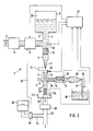
- FIG. 2 shows a modified embodiment which basically works exactly like the device according to FIG. 1.
- the device shown in FIG. 2 differs from that according to FIG. 1 in that measures are still taken on the consumer side in order to close the device to make a pressure device, for example for connecting bedpans (for example in hospitals), foot showers, spray lances, spray hoses and the like.
- a check valve 33 is arranged in the outlet line 22, to which is connected on the outlet side a line 32 which can be connected to a consumer and which is connected via a branch line 34 to a pressure expansion tank 38.
- a pressure switch 36 by means of which the inlet line 2 can be blocked as a function of the outlet pressure, which can be done by appropriately controlling the solenoid valve 9 via a line 40, as shown in FIG. 2.
- the pressure accumulator 38 is pressurized with compressed air.
- the pressure switch 36 closes the solenoid valve 9 at a presettable outlet pressure (for example 2 bar), so that a further inflow into the outlet line is blocked until the outlet pressure again falls below the threshold value (here for example 2 bar). Blocking the inlet line via the solenoid valve 9 creates a pressure difference in the lines 22 and 32, as a result of which the check valve 30 closes. If the outlet pressure then falls below the threshold value, the pressure difference also disappears. The solenoid valve releases the feed line again and the check valve opens again.
- a presettable outlet pressure for example 2 bar
- a collecting container 44 is provided, the amount of liquid of which can be scanned with the aid of a liquid level sensor 46.
- This scanner 46 is preferably connected to the control device 27, as shown, for signaling a maximum liquid level.
- FIG. 3 shows a simplified embodiment of the device according to FIGS. 1 or 2.
- the inlet line 2 is connected directly to the inlet connection 6 of the injector 7.
- a tube aerator 48 is arranged in the inlet line 2 or the outlet line 4.
- a liquid level sensor 10 ' can also be provided, which directly senses the liquid level in the pressure equalization container 3 and whose measurement signal is fed to the control device 27 for evaluation, as shown in broken lines in FIG. 1.
Abstract
Description
Die Erfindung betrifft eine Vorrichtung zum Mischen von Flüssigkeiten gemäß Oberbegriff des Anspruchs 1.The invention relates to a device for mixing liquids according to the preamble of
Durch die DE-OS 34 00 263 ist eine Vorrichtung zum Mischen von Wasser und einem Desinfektionsmittelkonzentrat bekannt. Das Wasser wird über eine Leitung aus dem Wassernetz entnommen und strömt über eine elektrische Wassermangelsicherung, ein Entnahmeventil und ein elektrisch betätigbares Magnetventil sowie einen Rohrbelüfter mit einem Durchflußmengenregler zu einem Injektordosierkopf, der als Wasserstrahlpumpe ausgebildet ist, die über eine Saugleitung Desinfektionsmittelkonzentrat aus einem Kanister ansaugt und dem durchfließenden Wasser zumischt. Ein Sensor überwacht die Leitfähigkeit und Temperatur der hergestellten Desinfektionsmittellösung. In einem Steuergerät werden die ermittelten Werte mit Sollwerten verglichen. Bei Abweichung wom Sollwert wird das Magnetventil angesteuert, das die Wasserzufuhr zur Wasserstrahlpumpe sperrt, wodurch gleichzeitig die Zufuhr des Lösungsmittelkonzentrats gestoppt wird. Nachteilig ist, daß die Dosierung unmittelbar vom Wasserdruck abhängt. Da nur bei konstantem Wasserdruck eine ausreichend genaue Dosierung erreichbar ist, arbeitet die bekannte Vorrichtung bei Druckschwankungen ungenau. Es besteht die Gefahr, daß hierdurch der gemessene Leitfähigkeitswert zu stark vom Sollwert abweicht, was eine Zwangsabschaltung der Vorrichtung über das Magnetventil und eine Fehlermeldung zur Folge hat. Nachteilig ist ferner, daß die Trennung zwischen Wassernetz und Desinfektionsmittelkonzentrat bzw. Desinfektionsmittellösung nicht gewährleistet ist, da die eingesetzten Ventile keine ausreichende Sicherheit gegen einen Rückfluß von Desinfektionsmittellösung und damit gegen eine Verunreinigung des Leitungswassers bieten.From DE-OS 34 00 263 a device for mixing water and a disinfectant concentrate is known. The water is removed from the water network via a line and flows via an electrical low water protection device, a removal valve and an electrically operated solenoid valve as well as a pipe aerator with a flow regulator to an injector metering head, which is designed as a water jet pump, which draws in disinfectant concentrate from a canister via a suction line and mixed with the flowing water. A sensor monitors the conductivity and temperature of the disinfectant solution produced. The determined values are compared with setpoints in a control unit. If there is a deviation from the setpoint, the solenoid valve is activated, which blocks the water supply to the water jet pump, which simultaneously stops the supply of the solvent concentrate. The disadvantage is that the dosage depends directly on the water pressure. Since a sufficiently precise dosage can only be achieved at constant water pressure, the known device works imprecisely in the event of pressure fluctuations. There is a risk that the measured conductivity value deviates too much from the setpoint value, which results in a forced shutdown of the device via the solenoid valve and an error message. Another disadvantage is that the separation between the water network and disinfectant concentrate or disinfectant solution is not guaranteed, since the valves used do not offer sufficient security against a backflow of disinfectant solution and thus against contamination of the tap water.
Die Aufgabe der vorliegenden Erfindung besteht darin, eine Vorrichtung gemäß Oberbegriff des Anspruchs 1 so auszubilden, daß die Dosiergenauigkeit auch bei Druckschwankungen der unter Druck befindlichen Flüssigkeit erhalten bleibt und ein Rückfluß mit Sicherheit verhindert ist.The object of the present invention is to design a device according to the preamble of
Diese Aufgabe wird durch die Ausbildung gemäß Kennzeichen des Anspruchs 1 gelöst.This object is achieved by the training according to the characterizing part of
Durch die erfindungsgemäße Ausbildung wird unabhängig vom Druck der zugeführten Flüssigkeit ein gleichmäßiger Flüssigkeitsdruck für den Injektor eingestellt, wodurch eine gleichmäßige Dosierung für jedes einstellbare Mischungsverhältnis der Flüssigkeiten erzielbar ist. Durch den vorgesehenen Luftspalt ist eine absolute Trennung zwischen den zu mischenden Flüssigkeiten und insbesondere zwischen der unter Druck dem Injektor zugeführten Flüssigkeit und der Flüssigkeitsmischung erzielbar, wodurch eine Verunreinigung der unter Druck zugeführten Flüssigkeit mit Sicherheit vermieden ist. Für die Herstellung von Desinfektionsmittellösungen aus Wasser, das aus dem Wassernetz zugeführt wird und einem Desinfektionsmittelkonzentrat bedeutet dies, daß mit Sicherheit die Gefahr einer Kontermination des Leitungswassers des Wassernetzes durch Rückfluß von Desinfektionsmittellösung verhindert ist.By means of the design according to the invention, a uniform liquid pressure is set for the injector regardless of the pressure of the liquid supplied, as a result of which a uniform dosage can be achieved for each adjustable mixing ratio of the liquids. The air gap provided makes it possible to achieve an absolute separation between the liquids to be mixed and, in particular, between the liquid fed to the injector under pressure and the liquid mixture, thereby reliably avoiding contamination of the liquid fed under pressure. For the production of disinfectant solutions from water that is supplied from the water network and a disinfectant concentrate, this means that the risk of contamination of the tap water of the water network by backflow of disinfectant solution is prevented with certainty.
Vorteilhafte und zweckmäßige Weiterbildungen der erfindungsgemäßen Aufgabenlösung sind in den Unteransprüchen gekennzeichnet.Advantageous and expedient developments of the task solution according to the invention are characterized in the subclaims.
Die Erfindung soll nachfolgend anhand der beigefügten Zeichnung, in der ein Ausführungsbeispiel dargestellt ist, näher erläutert werden.The invention will be explained below with reference to the accompanying drawing, in which an embodiment is shown.
Es zeigt
- Fig. 1 eine erste Ausfürhrungsform der erfindungsgemäßen Vorrichtung,
- Fig. 2 eine zweite Ausführungsform der erfindungsgemäßen Vorrichtung und
- Fig. 3 eine vereinfachte Ausführungsform der erfindungsgemäßen Vorrichtung nach Fig. 1 oder Fig. 2.
- 1 shows a first embodiment of the device according to the invention,
- Fig. 2 shows a second embodiment of the device according to the invention and
- 3 shows a simplified embodiment of the device according to the invention according to FIG. 1 or FIG. 2.
Die Zeichnung zeigt eine Vorrichtung 1 zum Mischen von Flüssigkeiten. Die Vorrichtung 1 weist eine Zulaufleitung 2 auf, über die unter Druck stehende Flüssigkeit, beispielsweise Wasser,aus dem Wassernetz zuführbar ist. Die Zulaufleitung 2 führt zu einem Druckausgleichsbehälter 3, bei dem Ausführungsbeispiel nach der Zeichnung speziell in eine Auslaßleitung 4 des Druckausgleichsbehälters 3. Die Auslaßleitung 4 verbindet den Ausgang 5 des Druckausgleichsbehälters 3 mit einem Einlaß 6 eines Injektors 7.The drawing shows a
In der Zulaufleitung 2 befinden sich ein Druckminderer 8 sowie ein Magnetventil 9. An die Auslaßleitung 4 des Druckausgleichsbehälters 3 ist ein Druckschalter 10 angeschlossen. Das Ende der Auslaßleitung 4 ist als Düse 11 ausgebildet, vor der in der Auslaßleitung ein Strahlregler 12 angeordnet ist.A
Der Injektor 7 ist nach Art einer Wasserstrahlpumpe ausgebildet. Am Einlaß 6 des Injektors 7 ist eine weitere Düse 13 angeschlossen bzw. der Einlaß 6 ist als Düse 13 ausgebildet. Die Düsen 11 und 13 sind nicht fest miteinander verbunden, sondern zwischen beiden befindet sich ein Luftspalt 14 von etwa 20 mm.The injector 7 is designed in the manner of a water jet pump. A
Der Injektor 7 weist einen Saugstutzen 15 auf, an den eine Saugleitung angeschlossen ist, die mit einer Sauglanze 17 verbunden ist, die in einen Vorratzbehälter 18 rägt, der eine zweite, der unter Druck befindlichen Flüssigkeit zuzumischende Flüssigkeit, beispielsweise ein Desinfektionsmittelkonzentrat, enthält. In der Saugleitung 16 sind ein Rückflußverhinderer 19 und eine Düse 20 angeordnet.The injector 7 has a
An den Auslaß 21 des Injektors 7 ist eine Ausgangsleitung 22 angeschlossen, in der ein Strahlregler 23 angeordnet ist.An
An die Düse 13 ist ein Sensor 24 zur Niveauüberwachung angeschlossen. Der Sensor 24 soll ein überlaufen der Düse 13 verhindern.A
Zur Durchflußkontrolle der Flüssigkeit aus dem Vorratsbehälter 18 ist ein Sensor 25 vorgesehen, der eine Leitwertmessung durchführt. An die Sauglanze ist eine Meßsonde zur Füllstandskontrolle angeschlossen.To control the flow of the liquid from the
Die Ausgangssignale des Druckschalters 10, des Niveauüberwachungssensors 24, des Durchflußkontrollsensors 25 und der Füllstandsmeßsonde 26 werden einer Steuereinrichtung 27 zur Verarbeitung und Ausgabe von Steuersignalen zugeführt.The output signals of the
Die Vorrichtung arbeitet wie folgt:
Die über die Zulaufleitung 2 zulaufende unter Druck befindliche Flüssigkeit strömt in den Druckausgleichsbehälter 3 nach Durchlaufen des Druckminderers 8 und des Magnetventiles 9. Beim Füllen des Druckausgleichsbehälters wird die im Druckausgleichsbehälter befindliche Luftsäule 28 komprimiert, bis ein bestimmter Flüssigkeitsdruck erreicht ist, der durch den Druckschalter 10 abgetastet wird, dessen Ausgangssignal in der Steuereinrichtung 27 ausgewertet wird, die bei Erreichen des Voreinstellbaren Druckes des Magnetventil zum Schließen ansteuert. Auf diese Weise kann ein bestimmter Flüssigkeitsdruck der dem Injektor 7 zuzuführenden Flüssigkeit eingeregelt werden, welcher geringfügig um einen Mittelwert schwankt.The device works as follows:
The pressurized liquid flowing in via the
Die aus dem Druckausgleichsbehälter aus tretende Flüssigkeit verläßt als Flüssigkeitsstrahl gut gebündelt die Düse 11 und strömt dann nach dem Durchströmen des Luftspaltes 14 in die Düse 13 des Einlasses 6 des Injektors 7. Durch den die Düse 13 verlassenden Flüssigkeitsstrahl wird im Injektor ein konstanter Unterdruck erzeugt, durch den über die Saugleitung 16 aus dem Vorratsbehälter 18 die zuzumischende Flüssigkeit angesaugt wird. Diese Flüssigkeit wird im Injektor 7 der Flüssigkeit aus dem Druckausgleichsbehälter zugemischt und die Mischung fließt aus der Ausgangsleitung 22 ab.The liquid emerging from the surge tank leaves the
Die Menge der aus dem Vorratsbehälter 18 angesaugten Flüssigkeit wird bestimmt durch die Einstellung der Düse 20 in der Saugleitung und durch den im Druckausgleichsbehälter konstant gehaltenen Druck, was bedeutet, daß das Mischungsverhältnis durch die Düse 20 und den Druck im Druckausgleichsbehälter bestimmt wird.The amount of liquid drawn from the
Die Fig. 2 zeigt eine modifizierte Ausführungsform, welche grundsätzlich genauso arbeitet wie die Vorrichtung nach Fig. 1. Die in der Fig. 2 dargestellte Vorrichtung unterscheidet sich von der nach Fig. 1 dadurch, daß Verbraucherseitig noch Maßnahmen getroffen sind, um die Vorrichtung zu einem Druckgerät, beispielsweise zum Anschluß von Steckbecken (beispielsweise in Krankenhäusern), Fußduschen, Sprühlanzen, Spritzschläuchen und dergleichen zu machen. Hierzu ist in der Ausgangsleitung 22 ein Rückschlagventil 33 angeordnet, an das sich ausgangsseitig eine an einen Verbraucher anschließbare Leitung 32 anschließt, die über eine Abzweigleitung 34 mit einem Druckausgleichsbehälter 38 verbunden ist. In der Leitung 34 befindet sich ein Druckschalter 36, durch den die Zulaufleitung 2 in Abhängigkeit vom Ausgangsdruck sperrbar ist, was durch entsprechende Steuerung des Magnetventiles 9 über eine Leitung 40 erfolgen kann, wie dies in der Fig. 2 dargestellt ist. Der Druckspeicher 38 ist mit Druckluft beaufschlagt.FIG. 2 shows a modified embodiment which basically works exactly like the device according to FIG. 1. The device shown in FIG. 2 differs from that according to FIG. 1 in that measures are still taken on the consumer side in order to close the device to make a pressure device, for example for connecting bedpans (for example in hospitals), foot showers, spray lances, spray hoses and the like. For this purpose, a check valve 33 is arranged in the
Der Druckschalter 36 schließt das Magnetventil 9 bei einem voreinstellbaren Ausgangsdruck (beispielsweise 2 bar), so daß ein weiterer Zufluß in die Ausgangsleitung gesperrt ist, bis der Ausgangsdruck den Schwellwert (hier beispielsweise 2 bar) wieder unterschreitet. Durch das Sperren der Zulaufleitung über das Magnetventil 9 entsteht ein Druckunterschied in den Leitungen 22 und 32, wodurch das Rückschlagventil 30 schließt. Wenn danach der Ausgangsdruck wieder unter den Schwellwert fällt, verschwindet auch der Druckunterschied. Das Magnetventil gibt die Zulaufleitung wieder frei, und das Rückschlagventil geht wieder in Offenstellung.The
Es kann unter Umständen etwas Tropfwasser bei der Vorrichtung gemäß Fig. 2 über den Spalt 14 austreten. Zum Auffangen dieses Tropfwassers ist ein Auffangebehälter 44 vorgesehen, dessen Flüssigkeitsmenge mit Hilfe eines Flüssigkeitspegeltasters 46 abtastbar ist. Dieser Abtaster 46 ist vorzugsweise mit der Steuereinrichtung 27 verbunden, wie dies dargestellt ist, zur Signalisierung eines maximalen Flüssigkeitsstandes.Under certain circumstances, some dripping water can escape through the
Die Fig. 3 zeigt eine vereinfachte Ausführungsform der Vorrichtung nach den Fig. 1 oder 2. Unter Weglassung des Luftspaltes 14 ist die Zulaufleitung 2 direkt mit dem Einlaßstutzen 6 des Injektors 7 verbunden. Zur Verbesserung des Strömungsverhaltens ist in der Zulaufleitung 2 oder der Auslaßleitung 4 ein Rohrbelüfter 48 angeordnet. In Verbindung mit der Beschreibung der Fig. 1 ist oben angegeben, den Flüssigkeitsdruck mit Hilfe eines Druckschalters 10 abzutasten. Anstelle eines solchen Druckschalters 10 kann auch ein Flüssigkeitspegeltaster 10' vorgesehen sein, der den Flüssigkeitsstand im Druckausgleichsbehälter 3 unmittelbar abtastet und dessen Meßsignal der Steuereinrichtung 27 zur Auswertung zugeführt wird, wie dies in der Fig. 1 gestrichelt eingezeichnet ist.3 shows a simplified embodiment of the device according to FIGS. 1 or 2. With the
Claims (16)
Applications Claiming Priority (2)
| Application Number | Priority Date | Filing Date | Title |
|---|---|---|---|
| DE3536992A DE3536992C1 (en) | 1985-10-17 | 1985-10-17 | Device for mixing liquids |
| DE3536992 | 1985-10-17 |
Publications (2)
| Publication Number | Publication Date |
|---|---|
| EP0219800A2 true EP0219800A2 (en) | 1987-04-29 |
| EP0219800A3 EP0219800A3 (en) | 1988-03-09 |
Family
ID=6283796
Family Applications (1)
| Application Number | Title | Priority Date | Filing Date |
|---|---|---|---|
| EP86114192A Withdrawn EP0219800A3 (en) | 1985-10-17 | 1986-10-14 | Mixing device for liquids |
Country Status (3)
| Country | Link |
|---|---|
| EP (1) | EP0219800A3 (en) |
| JP (1) | JPS6415124A (en) |
| DE (1) | DE3536992C1 (en) |
Cited By (3)
| Publication number | Priority date | Publication date | Assignee | Title |
|---|---|---|---|---|
| EP0443963A1 (en) * | 1990-02-23 | 1991-08-28 | Hospal Industrie | Detector for detection of the flow of a first liquid in a circulation of a second liquid |
| EP0465336A1 (en) * | 1990-07-03 | 1992-01-08 | Claude-Jean Desvigne | Liquid products dosing device for agricultural vehicles |
| US20140169121A1 (en) * | 2011-07-20 | 2014-06-19 | Seko, S.P.A. | Mixing apparatus assembly with air gap separation, in particular for backflow prevention |
Families Citing this family (1)
| Publication number | Priority date | Publication date | Assignee | Title |
|---|---|---|---|---|
| DE102016001626B4 (en) | 2015-02-13 | 2022-02-17 | Schulz Gmbh | Process for providing a disinfectant or cleaning concentrate |
Citations (6)
| Publication number | Priority date | Publication date | Assignee | Title |
|---|---|---|---|---|
| DE307544C (en) * | ||||
| US206427A (en) * | 1878-07-30 | Improvement in printersj chases | ||
| US3094135A (en) * | 1959-03-10 | 1963-06-18 | Hydraulique & Urbanisme | Arrangement for feeding a reagent in amounts proportional to the output of water to be treated by said reagent |
| US3376886A (en) * | 1966-06-03 | 1968-04-09 | Chemagnetics Controls Corp | Universal chemical feeder |
| US4094786A (en) * | 1977-10-11 | 1978-06-13 | Bury John R | Treatment control apparatus for water systems |
| EP0143294A2 (en) * | 1983-10-29 | 1985-06-05 | Weber Apparatebau GmbH | Apparatus for dosing a component to a solvent or diluent |
Family Cites Families (1)
| Publication number | Priority date | Publication date | Assignee | Title |
|---|---|---|---|---|
| DE3400263A1 (en) * | 1984-01-05 | 1985-07-18 | Göldner - Vieregge-Bruns Hygienetechnik GmbH, 3070 Nienburg | Device for monitoring the concentration at which disinfectant solutions are used |
-
1985
- 1985-10-17 DE DE3536992A patent/DE3536992C1/en not_active Expired
-
1986
- 1986-10-14 EP EP86114192A patent/EP0219800A3/en not_active Withdrawn
- 1986-10-17 JP JP61245625A patent/JPS6415124A/en active Pending
Patent Citations (6)
| Publication number | Priority date | Publication date | Assignee | Title |
|---|---|---|---|---|
| DE307544C (en) * | ||||
| US206427A (en) * | 1878-07-30 | Improvement in printersj chases | ||
| US3094135A (en) * | 1959-03-10 | 1963-06-18 | Hydraulique & Urbanisme | Arrangement for feeding a reagent in amounts proportional to the output of water to be treated by said reagent |
| US3376886A (en) * | 1966-06-03 | 1968-04-09 | Chemagnetics Controls Corp | Universal chemical feeder |
| US4094786A (en) * | 1977-10-11 | 1978-06-13 | Bury John R | Treatment control apparatus for water systems |
| EP0143294A2 (en) * | 1983-10-29 | 1985-06-05 | Weber Apparatebau GmbH | Apparatus for dosing a component to a solvent or diluent |
Cited By (5)
| Publication number | Priority date | Publication date | Assignee | Title |
|---|---|---|---|---|
| EP0443963A1 (en) * | 1990-02-23 | 1991-08-28 | Hospal Industrie | Detector for detection of the flow of a first liquid in a circulation of a second liquid |
| EP0465336A1 (en) * | 1990-07-03 | 1992-01-08 | Claude-Jean Desvigne | Liquid products dosing device for agricultural vehicles |
| FR2664179A1 (en) * | 1990-07-03 | 1992-01-10 | Desvigne Claude Jean | APPARATUS FOR METERING LIQUID PRODUCTS FOR AGRICULTURAL MACHINERY. |
| US20140169121A1 (en) * | 2011-07-20 | 2014-06-19 | Seko, S.P.A. | Mixing apparatus assembly with air gap separation, in particular for backflow prevention |
| US9375688B2 (en) * | 2011-07-20 | 2016-06-28 | Seko S.P.A. | Mixing apparatus assembly with air gap separation, in particular for backflow prevention |
Also Published As
| Publication number | Publication date |
|---|---|
| JPS6415124A (en) | 1989-01-19 |
| EP0219800A3 (en) | 1988-03-09 |
| DE3536992C1 (en) | 1987-02-19 |
Similar Documents
| Publication | Publication Date | Title |
|---|---|---|
| DE69809394T3 (en) | CLEANING DEVICE AND METHOD FOR CLEANING AT LEAST ONE PART OF A MELKING MACHINE WITH A RINSING LIQUID | |
| DE2720210B2 (en) | Apparatus for calibrating a probe in a blood sample measuring device | |
| DE69826804T2 (en) | Liquid distribution device and method | |
| DE3400263C2 (en) | ||
| DE3339420C2 (en) | ||
| DE1646030A1 (en) | Powder feed device for a flame spray gun | |
| DE102005002448B4 (en) | Apparatus and method for measuring, controlling or testing | |
| DE2313407A1 (en) | DEVICE FOR SUPPLYING PRESSURE LIQUID TO A SERVO DEVICE | |
| EP0219800A2 (en) | Mixing device for liquids | |
| DE3015215A1 (en) | DEVICE FOR THE DOSED DELIVERY OF A COMPRESSED GAS-SHAPED MEDIUM | |
| EP0432673A2 (en) | Mobile apparatus for producing active water-based solutions | |
| DE1947549A1 (en) | Milking system | |
| WO2016150993A1 (en) | Method and device for the regulated transfer of a gas into a fluid medium | |
| EP0155683B1 (en) | Method and device for the preparation of liquids for fertilizer pouring of plants for household or hobby gardeners | |
| EP0028364A2 (en) | Apparatus for the infusion of liquids | |
| DE2738531C2 (en) | Device for dosing an additional liquid into a main liquid | |
| DE602004001491T2 (en) | Ventilation system with a reverse osmosis filter cartridge | |
| DE102009017126B4 (en) | Water treatment process and device therefor | |
| DE2556245C2 (en) | Mixing device for a foam extinguisher | |
| EP0580881A1 (en) | Apparatus for degassing liquids in liquid circuits | |
| CH639566A5 (en) | DOSING DEVICE FOR DOSING A GAS ADDED IN LIQUIDS. | |
| EP1517213B1 (en) | Dosing device for the production of a ready-to-use disinfectant solution from concentrates | |
| DE4329784A1 (en) | Drinks tapping system having a drinks metering device and a cleaning device | |
| DE19936374A1 (en) | Gas pressure control system | |
| DE2658451A1 (en) | Liq. volume control for field sprayer - has return lines connected to three way taps, and with servo-elements to vary flow cross-section |
Legal Events
| Date | Code | Title | Description |
|---|---|---|---|
| PUAI | Public reference made under article 153(3) epc to a published international application that has entered the european phase |
Free format text: ORIGINAL CODE: 0009012 |
|
| AK | Designated contracting states |
Kind code of ref document: A2 Designated state(s): AT BE CH DE FR GB IT LI LU NL SE |
|
| PUAL | Search report despatched |
Free format text: ORIGINAL CODE: 0009013 |
|
| AK | Designated contracting states |
Kind code of ref document: A3 Designated state(s): AT BE CH DE FR GB IT LI LU NL SE |
|
| STAA | Information on the status of an ep patent application or granted ep patent |
Free format text: STATUS: THE APPLICATION IS DEEMED TO BE WITHDRAWN |
|
| 18D | Application deemed to be withdrawn |
Effective date: 19880912 |