EP0218464B1 - Chair and method of producing a chair - Google Patents
Chair and method of producing a chair Download PDFInfo
- Publication number
- EP0218464B1 EP0218464B1 EP86307545A EP86307545A EP0218464B1 EP 0218464 B1 EP0218464 B1 EP 0218464B1 EP 86307545 A EP86307545 A EP 86307545A EP 86307545 A EP86307545 A EP 86307545A EP 0218464 B1 EP0218464 B1 EP 0218464B1
- Authority
- EP
- European Patent Office
- Prior art keywords
- tubular means
- chair
- engaging
- frame
- tubular
- Prior art date
- Legal status (The legal status is an assumption and is not a legal conclusion. Google has not performed a legal analysis and makes no representation as to the accuracy of the status listed.)
- Expired - Lifetime
Links
- 238000000034 method Methods 0.000 title claims description 9
- NJPPVKZQTLUDBO-UHFFFAOYSA-N novaluron Chemical compound C1=C(Cl)C(OC(F)(F)C(OC(F)(F)F)F)=CC=C1NC(=O)NC(=O)C1=C(F)C=CC=C1F NJPPVKZQTLUDBO-UHFFFAOYSA-N 0.000 claims abstract description 9
- 238000000576 coating method Methods 0.000 claims description 18
- 239000011248 coating agent Substances 0.000 claims description 15
- 238000000465 moulding Methods 0.000 claims description 4
- 238000003780 insertion Methods 0.000 claims description 2
- 230000037431 insertion Effects 0.000 claims description 2
- 238000007493 shaping process Methods 0.000 claims description 2
- 230000008878 coupling Effects 0.000 claims 7
- 238000010168 coupling process Methods 0.000 claims 7
- 238000005859 coupling reaction Methods 0.000 claims 7
- 239000004033 plastic Substances 0.000 abstract description 2
- 229920003023 plastic Polymers 0.000 abstract description 2
- 238000005253 cladding Methods 0.000 abstract 2
- 229910000831 Steel Inorganic materials 0.000 description 17
- 239000010959 steel Substances 0.000 description 17
- JOYRKODLDBILNP-UHFFFAOYSA-N Ethyl urethane Chemical compound CCOC(N)=O JOYRKODLDBILNP-UHFFFAOYSA-N 0.000 description 4
- 238000004519 manufacturing process Methods 0.000 description 4
- 238000012423 maintenance Methods 0.000 description 2
- 239000002991 molded plastic Substances 0.000 description 2
- 229920002635 polyurethane Polymers 0.000 description 2
- 239000004814 polyurethane Substances 0.000 description 2
- 239000007787 solid Substances 0.000 description 2
- 238000005452 bending Methods 0.000 description 1
- 238000005266 casting Methods 0.000 description 1
- 239000000428 dust Substances 0.000 description 1
- 239000013536 elastomeric material Substances 0.000 description 1
- 239000006260 foam Substances 0.000 description 1
- 230000003068 static effect Effects 0.000 description 1
- 230000003319 supportive effect Effects 0.000 description 1
- 238000003466 welding Methods 0.000 description 1
- 238000013316 zoning Methods 0.000 description 1
Images





Classifications
-
- A—HUMAN NECESSITIES
- A47—FURNITURE; DOMESTIC ARTICLES OR APPLIANCES; COFFEE MILLS; SPICE MILLS; SUCTION CLEANERS IN GENERAL
- A47C—CHAIRS; SOFAS; BEDS
- A47C5/00—Chairs of special materials
- A47C5/04—Metal chairs, e.g. tubular
- A47C5/08—Tubular chairs having sheathed tubes; Adaptation of sheathed tubes thereto
-
- A—HUMAN NECESSITIES
- A47—FURNITURE; DOMESTIC ARTICLES OR APPLIANCES; COFFEE MILLS; SPICE MILLS; SUCTION CLEANERS IN GENERAL
- A47C—CHAIRS; SOFAS; BEDS
- A47C5/00—Chairs of special materials
- A47C5/04—Metal chairs, e.g. tubular
Definitions
- the present invention relates to a chair comprising a frame including first and second tubular means for a differentiated rigidity and to a method for producing the same.
- the invention is concerned more specifically with a chair as set forth in the introductory part of claim 1 and with a method as set forth in the introductory part of claim 8.
- a chair with a frame made of first and second tubular means is known (GB-A-451909) wherein a seat portion of the chair frame includes a first tubular means of given outer and inner surfaces, wherein the back portion of the frame is formed with a second tubular means of outer cylindrical surface having a diameter smaller than the diameter of the first tubular means and wherein the second tubular means is partially lodged in the first tubular means to increase the rigidity of the back portion of the frame.
- the desired configuration of the frame is obtained by mechanical deformation of the first tubular means and the portion of the second tubular means lodged therein.
- the two tubular means provide common bends through 90° which guarantee a substantial rigidity to the back portion and a certain flexibility to its back portion. No covering of the tubular means is provided.
- Such a chair has the disadvantage of questionable aesthetics and comfort, and requiring three-dimensional deformations of tube members and/or weldings to reach the desired configuration of the frame. It also does not allow obtaining shapes of complex type in the frame.
- Another chair is known (US-A-4,361,357) wherein the frame is formed by a single tubing member defining the seat portion and the back portion of the chair and which is covered by a single elastomeric coating.
- the seat portion of the frame is engaged with suitable ends of a four arm base which increases the rigidity of the seat portion.
- This chair is costly in view of the high cost in shaping the frame and the base three-dimensionally, in covering the same with the elastomeric coating in its three-dimensional shape and in the requirements of the connections between the back portion of the frame and the ends of the base member.
- the object of the present invention is to provide a chair which is comfortable, inexpensive, rugged and decorative and a method for simple production of the said chair.
- the present invention provides a chair according to claim 1.
- the invention further provides a method of producing a chair according to claim 8.
- a chair embodying the invention has a frame which is black self-skinning urethane moulded on to a tubular steel frame.
- the steel frame is made of separate parts with a difference in the diameters of the tubular parts designed to enable each section of the frame to respond to the flexibility demands made upon it.
- the configuration of the frame provides slots for the insertion and removal of the seat and back shells.
- the seat and the back of the chair are flexible moulded plastics shells which attach to the frame with a snap-in or slide-in configuration for easy assembly, maintenance and replacement.
- a pin is used for additional security to prevent any accidental or unintended removal of the shell.
- the upright of the chair will accommodate a wide variety of standard or custom designed raise and lower swivel devices.
- a five legged star base can accommodate casters and glides, and can be manufactured by various techniques including steel stamping and plastics casting.
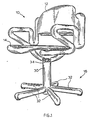
- a first chair embodying the invention is shown in Figs. 1, 2 and 3 in fully assembled condition.
- the main portions of the chair as seen in these figures are frame 10, back 12, seat 14 and pedestal 16.
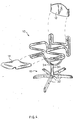
- Fig.4 The chair is shown in exploded view in Fig.4 which illustrates generally the manner in which these parts go together.
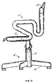
- the frame 10 is the primary portion of the chair and is shown particularly in Figs. 5 to 9 in various stages of fabrication and assembly.
- a back support member 18, right arm support member 20, left arm support member 22, left seat support member 24 and right seat support member 26 are steel members which, when assembled, provide the mechanical or structural support for the frame 10 with the elastomeric coating which is indicated by the numeral 28 providing clothing or covering thereof.
- the back support member 18 comprises a single steel rod which can be hollow tubing or solid with each of the ends formed into the shape of a "U".
- Back support legs 18a and 18b are respective legs of the ends so formed.
- the arm support members 20 and 22 are each a single hollow steel rod or steel tubing with a respective end of each formed into the shape of a "U" with respective legs 20a and 22b constructed and arranged to respectively receive back support legs 18a and 18b in the tubing in the assembled condition of the chair.
- the other ends of the arm support members 20 and 22 are formed generally into the shape of a "Z" with legs 20c and 22d respectively thereto lying generally in the same plane, which plane is generally perpendicular to the axes of the legs 20a and 22b.
- the term "generally” is used herein to indicate that these conditions are not critical and need not be precise to the chair design, assembly and/or usage.
- the seat support members 24 and 26 are also formed of hollow steel rods or tubing with a respective end of each formed into the shape of a "U" with respective legs 24c and 26c constructed and arranged to respectively receive seat support legs 20c and 22d in the tubing in the assembled condition of the chair.
- each seat support member slopes arcuately downwardly and is terminated in an end 24e, 26e designed to be attached to a suitable base or pedestal 16.
- the steel members are formed and bent as shown primarily in Fig.5.
- the diameter of the seat support members is greater than the diameter of the arm support members which is greater than the diameter of the back support members so that the various sections can be received in one another.
- the diameter of the seat support member is largest since it supports the greatest load in use.
- Different diameters of different sections allow the frame to be assembled, after forming and bending of individual frame members, by inserting one section into the next and also provides for "zoning" of flexibility throughout the frame.
- the frame is assembled generally in one plane as shown in Fig.6, without fasteners by sliding one section into the next, and placed in a two part mould where urethane foam, or other suitable elastomeric material is moulded onto the steel to provide a coating or clothing 28 as is illustrated in Fig. 7.
- the frame is then twisted into its three dimensional configuration and mounted in the upright 30 of the base 16.
- the twisting and rotational movement of the frame is achievable since the steel members can rotate with respect to each other.
- the urethane in addition to being a cover holds the steel members together.
- the urethane has a uniform outside diameter with differing inside diameters since it is moulded around the steel members of differing outside diameter.
- the frame 10 is mounted on the base by attaching seat support member ends 24e and 26e to the base upright 30.
- the base can be any suitable base and may be conventional.
- the base 16 has five legs 32, an upright 30 and swivel vertical 34 to which the ends 24e and 26e are suitably connected.
- the member 34 is supported within the upright 30 for rotational motion about a vertical axis.
- a tilt mechanism and/or means for raising or lowering the seat with respect to the floor can be incorporated.
- a cover 36 is provided for ornamental purposes and to protect the mechanism from dust and other foreign objects.
- the seat 14 and back 12 are flexible, moulded plastics shells which are attached to the frame with a snap-in or slide-in configuration for easy assembly, maintenance and replacement. Upholstering can be added if desired. Pins, not shown, can be used for additional security to prevent any accidental or unintended shell removal.
- the flexibility and shape of the seat and back shells, integrated with the flexibility and configuration of the frame provide a unique ergonomical comfort which eliminates the need for a tilt mechanism, although such can be included if desired.
- Fig.3 the solid lines indicate the static or unoccupied condition of the chair while the broken lines indicate the loaded or occupied condition.
- the application of load to the chair causes rotational movement of back and seat in the direction of the arrows "A" and a decrease in angle ⁇ without the use of a tilt mechanism, to a degree determined by the magnitude of the load.
- the degree of such rotational movement will be less for a person of lesser weight and greater for a person of greater weight, whereby the relationship of chair sections alters to provide a position unique to each user and his or her distributioon of weight.
- the chair sections will move to provide a comfortable and properly supportive chair to relative positions.
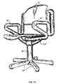
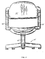
- FIG. 10 to 14 An alternative embodiment of the chair is shown in Figs. 10 to 14 wherein similar parts are identified by the numerals used in describing the embodiment of Fig. 1 with added primes.
- the essential difference in the second embodiment is in the introduction of the concept that the frame of the chair can be realized also with separate parts (every part made of a bended steel tube covered with a coat of polyurethane). Separate parts are coupled by fasteners as will be explained below.
- the main portions of the chair as seen in Figs. 10 to 14 are the frame 10', back 12', seat 14' and pedestal 16'.
- the frame 10' is the primary portion of the chair as explained in connection with the first embodiment.
- the back support member 18', right arm support member 20', left arm support member 22', left seat support member 26' and right seat support member 24' when assembled provide the mechanical or structural support for frame 10' with the elastomeric coating which is indicated by the numeral 28' providing clothing or covering thereof as seen best in Fig. 14.
- Each of these parts comprises a single steel rod, which can be hollow tubing or solid, bent to shape and covered with a suitable coating such as polyurethane before assembly.
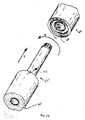
- the parts are coupled by means of any suitable fastening device 40, such as that shown in Fig.14 by way of example, for fastening two typical parts 42 and 44.
- Fastener 40 is provided with a spiral, bayonet slot 46 to receive a pin 48 of member 42 which is inserted therein in the direction of the arrow "A” and rotated in the direction of arrow "B” to fasten the parts 42 and 44 together.
- Fig. 14 is illustrative of the assembly of each of the pairs in the second embodiment of the invention as shown in Figs. 10 to 14.
Landscapes
- Chair Legs, Seat Parts, And Backrests (AREA)
- Chairs Characterized By Structure (AREA)
- Mutual Connection Of Rods And Tubes (AREA)
- Blow-Moulding Or Thermoforming Of Plastics Or The Like (AREA)
Abstract
Description
- The present invention relates to a chair comprising a frame including first and second tubular means for a differentiated rigidity and to a method for producing the same.
- The invention is concerned more specifically with a chair as set forth in the introductory part of claim 1 and with a method as set forth in the introductory part of claim 8.
- A chair with a frame made of first and second tubular means is known (GB-A-451909) wherein a seat portion of the chair frame includes a first tubular means of given outer and inner surfaces, wherein the back portion of the frame is formed with a second tubular means of outer cylindrical surface having a diameter smaller than the diameter of the first tubular means and wherein the second tubular means is partially lodged in the first tubular means to increase the rigidity of the back portion of the frame. In particular the desired configuration of the frame is obtained by mechanical deformation of the first tubular means and the portion of the second tubular means lodged therein. The two tubular means provide common bends through 90° which guarantee a substantial rigidity to the back portion and a certain flexibility to its back portion. No covering of the tubular means is provided. Such a chair has the disadvantage of questionable aesthetics and comfort, and requiring three-dimensional deformations of tube members and/or weldings to reach the desired configuration of the frame. It also does not allow obtaining shapes of complex type in the frame.
- Another chair is known (US-A-4,361,357) wherein the frame is formed by a single tubing member defining the seat portion and the back portion of the chair and which is covered by a single elastomeric coating. The seat portion of the frame is engaged with suitable ends of a four arm base which increases the rigidity of the seat portion. This chair is costly in view of the high cost in shaping the frame and the base three-dimensionally, in covering the same with the elastomeric coating in its three-dimensional shape and in the requirements of the connections between the back portion of the frame and the ends of the base member.
- The object of the present invention is to provide a chair which is comfortable, inexpensive, rugged and decorative and a method for simple production of the said chair.
- In accordance with this object, the present invention provides a chair according to claim 1. The invention further provides a method of producing a chair according to claim 8.
- A chair embodying the invention has a frame which is black self-skinning urethane moulded on to a tubular steel frame. The steel frame is made of separate parts with a difference in the diameters of the tubular parts designed to enable each section of the frame to respond to the flexibility demands made upon it. The configuration of the frame provides slots for the insertion and removal of the seat and back shells.
- The seat and the back of the chair are flexible moulded plastics shells which attach to the frame with a snap-in or slide-in configuration for easy assembly, maintenance and replacement. A pin is used for additional security to prevent any accidental or unintended removal of the shell.
- The upright of the chair will accommodate a wide variety of standard or custom designed raise and lower swivel devices. A five legged star base can accommodate casters and glides, and can be manufactured by various techniques including steel stamping and plastics casting.
- The invention will be described in more detail, by way of example, with reference to the accompanying drawings, in which:
- Fig.1 is a front perspective view of a fully assembled chair embodying the invention;
- Fig.2 is a front elevation of the chair shown in Fig. 1;
- Fig.3 is a side view of the chair shown in Fig.1 with the ergonomical movements of the chair illustrated by broken lines;
- Fig.4 is an exploded perspective view of the chair of Fig.1 illustrating the parts thereof;
- Fig.5 is an exploded perspective view of the steel frame of the chair with the elastomeric clothing absent;
- Fig.6 is a plan view of the steel frame in assembled condition in position for moulding of the elastomeric clothing thereon;
- Fig.7 is a sectional view of a section of frame with clothing:
- Fig.8 is a plan view of the frame with clothing prior to rotation of the various members for attachment to the pedestal;
- Fig.9 is a perspective view of the frame as shown in Fig.8 but with members rotated into position for attachment to the pedestal;
- Fig.10 is a view similar to Fig.1 but of an alternative embodiment of the invention;
- Fig.11 is a view similar to that of Fig.2 but of the chair shown in Fig.10;
- Fig.12 is a view somewhat similar to that of Fig.3 but of the chair shown in Fig.10;
- Fig.13 is a rear view of the chair shown in Fig. 10; and
- Fig.14 is a perspective exploded view of a segment of the chair of Fig.10 illustrating the manner of joint assembly of that embodiment.
- A first chair embodying the invention is shown in Figs. 1, 2 and 3 in fully assembled condition. The main portions of the chair as seen in these figures are
frame 10,back 12,seat 14 andpedestal 16. - The chair is shown in exploded view in Fig.4 which illustrates generally the manner in which these parts go together.
- The
frame 10 is the primary portion of the chair and is shown particularly in Figs. 5 to 9 in various stages of fabrication and assembly. Aback support member 18, rightarm support member 20, leftarm support member 22, leftseat support member 24 and rightseat support member 26 are steel members which, when assembled, provide the mechanical or structural support for theframe 10 with the elastomeric coating which is indicated by thenumeral 28 providing clothing or covering thereof. - The
back support member 18 comprises a single steel rod which can be hollow tubing or solid with each of the ends formed into the shape of a "U". Backsupport legs - The
arm support members respective legs 20a and 22b constructed and arranged to respectively receiveback support legs - The other ends of the
arm support members legs legs 20a and 22b. The term "generally" is used herein to indicate that these conditions are not critical and need not be precise to the chair design, assembly and/or usage. - The
seat support members respective legs 24c and 26c constructed and arranged to respectively receiveseat support legs - The remaining portion of each seat support member slopes arcuately downwardly and is terminated in an
end pedestal 16. - The steel members are formed and bent as shown primarily in Fig.5. The diameter of the seat support members is greater than the diameter of the arm support members which is greater than the diameter of the back support members so that the various sections can be received in one another. The diameter of the seat support member is largest since it supports the greatest load in use.
- Different diameters of different sections allow the frame to be assembled, after forming and bending of individual frame members, by inserting one section into the next and also provides for "zoning" of flexibility throughout the frame.
- The frame is assembled generally in one plane as shown in Fig.6, without fasteners by sliding one section into the next, and placed in a two part mould where urethane foam, or other suitable elastomeric material is moulded onto the steel to provide a coating or
clothing 28 as is illustrated in Fig. 7. - The frame is then twisted into its three dimensional configuration and mounted in the upright 30 of the
base 16. - The twisting and rotational movement of the frame is achievable since the steel members can rotate with respect to each other. The urethane in addition to being a cover holds the steel members together. The urethane has a uniform outside diameter with differing inside diameters since it is moulded around the steel members of differing outside diameter.
- As stated above, after fabrication the
frame 10 is mounted on the base by attaching seatsupport member ends base 16 has fivelegs 32, an upright 30 and swivel vertical 34 to which theends member 34 is supported within the upright 30 for rotational motion about a vertical axis. A tilt mechanism and/or means for raising or lowering the seat with respect to the floor can be incorporated. - A
cover 36 is provided for ornamental purposes and to protect the mechanism from dust and other foreign objects. - The
seat 14 andback 12 are flexible, moulded plastics shells which are attached to the frame with a snap-in or slide-in configuration for easy assembly, maintenance and replacement. Upholstering can be added if desired. Pins, not shown, can be used for additional security to prevent any accidental or unintended shell removal. - The flexibility and shape of the seat and back shells, integrated with the flexibility and configuration of the frame provide a unique ergonomical comfort which eliminates the need for a tilt mechanism, although such can be included if desired.
- In Fig.3 the solid lines indicate the static or unoccupied condition of the chair while the broken lines indicate the loaded or occupied condition. As shown therein, the application of load to the chair, as when one sits in it, causes rotational movement of back and seat in the direction of the arrows "A" and a decrease in angle ϑ without the use of a tilt mechanism, to a degree determined by the magnitude of the load. Hence the degree of such rotational movement will be less for a person of lesser weight and greater for a person of greater weight, whereby the relationship of chair sections alters to provide a position unique to each user and his or her distributioon of weight. Additionally as one moves within the chair the chair sections will move to provide a comfortable and properly supportive chair to relative positions.
- An alternative embodiment of the chair is shown in Figs. 10 to 14 wherein similar parts are identified by the numerals used in describing the embodiment of Fig. 1 with added primes.
- The essential difference in the second embodiment is in the introduction of the concept that the frame of the chair can be realized also with separate parts (every part made of a bended steel tube covered with a coat of polyurethane). Separate parts are coupled by fasteners as will be explained below.
- The main portions of the chair as seen in Figs. 10 to 14 are the frame 10', back 12', seat 14' and pedestal 16'.
- The frame 10' is the primary portion of the chair as explained in connection with the first embodiment. The back support member 18', right arm support member 20', left arm support member 22', left seat support member 26' and right seat support member 24' when assembled provide the mechanical or structural support for frame 10' with the elastomeric coating which is indicated by the numeral 28' providing clothing or covering thereof as seen best in Fig. 14.
- Each of these parts comprises a single steel rod, which can be hollow tubing or solid, bent to shape and covered with a suitable coating such as polyurethane before assembly.
- The parts are coupled by means of any
suitable fastening device 40, such as that shown in Fig.14 by way of example, for fastening twotypical parts 42 and 44. -
Fastener 40 is provided with a spiral,bayonet slot 46 to receive apin 48 ofmember 42 which is inserted therein in the direction of the arrow "A" and rotated in the direction of arrow "B" to fasten theparts 42 and 44 together. Fig. 14 is illustrative of the assembly of each of the pairs in the second embodiment of the invention as shown in Figs. 10 to 14. - The remainder of the assembly and operation and use of the chair of Figs. 10 to 14 are the same as in Figs. 1 to 9.
Claims (10)
- A chair comprising a frame (10) having a seat portion and a back portion, and first and second tubular means (24, 26; 20, 22), each having an outer cylindrical surface and an inner cylindrical surface and wherein the second tubular means (20, 22) defines the back portion and comprises engaging portions of their outer surfaces engaged in the inner surfaces of the first means (24, 26), characterized in that
the first tubular means (24, 26) defines the seat portion of the frame, has a rigidity greater than the rigidity of the second means (20, 22) and comprises two receiving ends (24c, 26d) in the said inner surfaces, close to the sides of a seat member (14) of the chair;
the engaging portions of the second tubular (20, 22) comprise two engaging ends of the outer surfaces which are engaged within the said two receiving ends;
the receiving ends in the first tubular means and the engaging ends of the second tubular means are connected to each other through a slidable and rotatable coupling; and
an elastomeric coating (28) covers the outer surface of the first means (24, 26) and the outer surface of the second means (20, 22) except for the engaging ends and includes sections rotated relative to each other between the first tubular means and the second tubular means adjacent to said receiving ends, and provides a substantial uniform outside surface on the said seat portion and back portion. - A chair in accordance with claim 1, characterized in that the frame (10) further comprises a pedestal (30) providing an upper end (34), the first tubular means (24, 26) comprises two lower portions which slope arcuately downwardly with respect to the seat member (14) and in that the first tubular means comprises two further receiving ends (24e, 26e) in the inner surfaces for engaging the upper end (34) of the pedestal (30).
- A chair in accordance with clad 1 or 2, characterized in that the second tubular means (20, 22) comprises two receiving ends (20a, 22b) in the inner cylindrical surface, opposite to said engaging ends (20c, 22d) and the back portion of the frame further comprises a third tubular means (18), having an outer cylindrical surface, an inner cylindrical surface and two engaging ends (18a, 18b) on the outer surface opposite each other, in which the engaging ends in the third tubular means are engaged in the receiving ends of the second tubular means through a further slidable and rotatable coupling and in which an elastomeric coating (28) is further provided to cover also the outer surface of the third tubular means except the said engaging ends (18a, 18b).
- A chair in accordance with any of the preceding claims, characterized in that the said first tubular means (24, 26) further comprises two seat tubing members ending with two "U" shaped portions close to the sides of the seat member (14) of the chair and each including an intermediate arm and a terminal arm, and in which the two receiving ends (24e, 26e) are located at the respective terminal arms in the said "U" shaped portions.
- A chair in accordance with claim 4, characterized in that the second tubular means (20, 22) comprises two arm tubing members including two respective vertical "Z" shaped portions each having a lower portion, an upper portion and a diagonal portion between the lower portion and the upper portion, in which the lower portions are disposed at the sides of the said seat member and the said engaging ends (20c, 22d) are located at the ends of the said lower portions and engage the said terminal arms in the "U" shaped portions, and in which the diagonal portions and the upper portions of the said "Z" shaped arms define an angle (ϑ) which is yieldably decreasable upon application of load to the chair.
- A chair in accordance with claims 3 and 5, characterized in that the third tubular means (18) comprises a back tubing member including a main horizontal portion and two vertical "U" shaped portions located at the sides of a back member (12) of the chair and each having an upward arm following the main portion and a downward arm defining one of said engaging ends (18a, 18b), in which the two arm tubing members end with two vertical "U" shaped portions each include each one a downward arm which follows said upper portion and an upward arm which defines one of the receiving ends (20a, 22b) to receive a respective engaging end (18a, 18b) of the downward arm of the back tubing member (18), and in which the said back member (12) has two sides located between the "U" shaped portions of the said back tubing member.
- A chair in accordance with any of the preceding claims characterized in that the slidable and rotatable coupling between the first tubular means (24, 26) and the second tubular means (20, 22), and optionally between the second tubular means (20, 22) and the third tubular means (18), includes a pin and slot connection between an engaging end and a respective receiving end, and wherein the elastomeric coating covers the said pin and slot connection and comprises a discontinuity adjacent to the said receiving ends.
- A method of producing a chair comprising a base member (16), a frame (10) having a seat portion and a back portion, and first and second tubular means (24, 26; 20, 22), each having an outer cylindrical surface and an inner cylindrical surface and wherein the second tubular means defines the back portion and comprises engaging portions of the outer surface engaged in the inner surface of the first means, the method being characterized by the steps of:
shaping the first tubular means (24, 26) to form the seat portion of the frame and to include two receiving ends (24c, 26d) in the said inner surface;
providing the engaging portions in the second tubular means (20, 22) to include two engaging ends in the outer surfaces to define a slidable and rotatable coupling with the two receiving ends in the first tubular means;
connecting the receiving ends of the first tubular means with the engaging ends of the second tubular means through sliding in the slidable and rotatable coupling;
covering the outer surface of the first means (24, 26) and the outer surface of the second means (20, 22) except the engaging ends with an elastomeric coating, either before the engaging of the engaging ends by moulding of singular elastomeric coatings on the first tubular means and the second tubular means or, in alternative, after insertion of the engaging ends in the receiving ends by moulding a continuous covering of the said first and second tubular means with an elastomeric coating, in order to obtain a substantially uniform outside surface in the said seat portion and back portion;
twisting the slideable and rotatable coupling to define the desired frame configuration, either through reciprocal rotation between the elastomeric coatings of the first tubular means and the second tubular means in the case of individual coatings, or, in alternative, through twisting of the elastomeric coating in the case of continuous covering; and
attaching and locking the said first tubular means to the base member (16) of the chair. - A method according to claim 8, characterized in that the slideable and rotatable coupling comprises a spiral bayonet slot (46) on the receiving end covered by the elastomeric coating and a pin (48) on the engaging end close to the elastomeric coating.
- A method according to claim 8, characterized in that, in the alternative case of continuous covering, the continuous covering is obtained by placing the first and the second tubular means in a generally flat posture within a mould, moulding the elastomeric coating about the tubular means and then removing the coated first and second tubular means from the mould.
Priority Applications (1)
| Application Number | Priority Date | Filing Date | Title |
|---|---|---|---|
| AT86307545T ATE63440T1 (en) | 1985-10-01 | 1986-10-01 | CHAIR AND METHOD OF MAKING A CHAIR. |
Applications Claiming Priority (2)
| Application Number | Priority Date | Filing Date | Title |
|---|---|---|---|
| US78250585A | 1985-10-01 | 1985-10-01 | |
| US782505 | 1985-10-01 |
Publications (3)
| Publication Number | Publication Date |
|---|---|
| EP0218464A2 EP0218464A2 (en) | 1987-04-15 |
| EP0218464A3 EP0218464A3 (en) | 1987-10-14 |
| EP0218464B1 true EP0218464B1 (en) | 1991-05-15 |
Family
ID=25126269
Family Applications (1)
| Application Number | Title | Priority Date | Filing Date |
|---|---|---|---|
| EP86307545A Expired - Lifetime EP0218464B1 (en) | 1985-10-01 | 1986-10-01 | Chair and method of producing a chair |
Country Status (6)
| Country | Link |
|---|---|
| EP (1) | EP0218464B1 (en) |
| JP (1) | JPS62167511A (en) |
| AT (1) | ATE63440T1 (en) |
| AU (1) | AU603997B2 (en) |
| DE (1) | DE3679270D1 (en) |
| ES (1) | ES2022121B3 (en) |
Families Citing this family (2)
| Publication number | Priority date | Publication date | Assignee | Title |
|---|---|---|---|---|
| AU603997B2 (en) * | 1985-10-01 | 1990-12-06 | Olivetti Synthesis, S.P.A. | Chair |
| JP4896631B2 (en) * | 2006-08-29 | 2012-03-14 | 株式会社イトーキ | Chair |
Family Cites Families (5)
| Publication number | Priority date | Publication date | Assignee | Title |
|---|---|---|---|---|
| DK51865C (en) * | 1935-01-23 | 1936-07-13 | Anton Lorenz | Furniture frame. |
| US4529246A (en) * | 1980-01-07 | 1985-07-16 | Leib Roger K | Patient chair |
| US4361357A (en) * | 1980-04-21 | 1982-11-30 | Pollock Charles R | Chair |
| BE900471A (en) * | 1984-08-30 | 1984-12-17 | Brasseur Thierry | Tubular furniture covering - consists of flexible, cylindrical sheaths which cover tube sections of seats etc. |
| AU603997B2 (en) * | 1985-10-01 | 1990-12-06 | Olivetti Synthesis, S.P.A. | Chair |
-
1986
- 1986-09-30 AU AU63519/86A patent/AU603997B2/en not_active Ceased
- 1986-10-01 EP EP86307545A patent/EP0218464B1/en not_active Expired - Lifetime
- 1986-10-01 DE DE8686307545T patent/DE3679270D1/en not_active Expired - Fee Related
- 1986-10-01 JP JP61234241A patent/JPS62167511A/en active Pending
- 1986-10-01 AT AT86307545T patent/ATE63440T1/en not_active IP Right Cessation
- 1986-10-01 ES ES86307545T patent/ES2022121B3/en not_active Expired - Lifetime
Also Published As
| Publication number | Publication date |
|---|---|
| ATE63440T1 (en) | 1991-06-15 |
| DE3679270D1 (en) | 1991-06-20 |
| EP0218464A3 (en) | 1987-10-14 |
| EP0218464A2 (en) | 1987-04-15 |
| AU603997B2 (en) | 1990-12-06 |
| JPS62167511A (en) | 1987-07-23 |
| ES2022121B3 (en) | 1991-12-01 |
| AU6351986A (en) | 1987-04-02 |
Similar Documents
| Publication | Publication Date | Title |
|---|---|---|
| US4892356A (en) | Chair shell | |
| EP0130229B1 (en) | One-piece shell chair | |
| US5320411A (en) | Flip-up seat construction | |
| US6705950B2 (en) | Non-motorized object hanger | |
| EP0608635B1 (en) | A bed base structure | |
| EP0824880A3 (en) | Stackable chair for a row of chairs in an auditorium or the like | |
| US20190053626A1 (en) | Connection Assembly for a Backrest and Office or Conference Chair | |
| IT9020119A1 (en) | ERGONOMIC SEAT | |
| US4361357A (en) | Chair | |
| US5501419A (en) | Chair leg assembly with three legs | |
| EP0386832A1 (en) | Pedestal with radial arms for chairs, furniture and the like, of variable dimensions | |
| KR0166388B1 (en) | Bed floor constructions | |
| US10932571B2 (en) | Rotatable chair back | |
| EP0405681A1 (en) | Reversibly deformable frame with upper members flexible in any direction and a lower horizontally deformable band for the backs of chairs and the like | |
| EP0345758B1 (en) | Chair base | |
| EP0262337B1 (en) | Conductive caster | |
| EP0218464A2 (en) | Chair and method of producing a chair | |
| EP0508516A1 (en) | Upholstered element with continuously unidirectionally shapable flat internal frame | |
| GB2169194A (en) | Undermattress | |
| EP3810060B1 (en) | Support structure | |
| JPH0111096Y2 (en) | ||
| EP0608025A1 (en) | Seat and bed frames rotating in relation to the variable-setting back | |
| EP0344718A1 (en) | Lounger | |
| CN215776736U (en) | Deformable furniture | |
| JPH0337469Y2 (en) |
Legal Events
| Date | Code | Title | Description |
|---|---|---|---|
| PUAI | Public reference made under article 153(3) epc to a published international application that has entered the european phase |
Free format text: ORIGINAL CODE: 0009012 |
|
| AK | Designated contracting states |
Kind code of ref document: A2 Designated state(s): AT BE CH DE ES FR GB IT LI NL |
|
| PUAL | Search report despatched |
Free format text: ORIGINAL CODE: 0009013 |
|
| AK | Designated contracting states |
Kind code of ref document: A3 Designated state(s): AT BE CH DE ES FR GB IT LI NL |
|
| 17P | Request for examination filed |
Effective date: 19880413 |
|
| 17Q | First examination report despatched |
Effective date: 19890811 |
|
| GRAA | (expected) grant |
Free format text: ORIGINAL CODE: 0009210 |
|
| AK | Designated contracting states |
Kind code of ref document: B1 Designated state(s): AT BE CH DE ES FR GB IT LI NL |
|
| PG25 | Lapsed in a contracting state [announced via postgrant information from national office to epo] |
Ref country code: NL Effective date: 19910515 Ref country code: LI Effective date: 19910515 Ref country code: CH Effective date: 19910515 Ref country code: AT Effective date: 19910515 |
|
| REF | Corresponds to: |
Ref document number: 63440 Country of ref document: AT Date of ref document: 19910615 Kind code of ref document: T |
|
| ITF | It: translation for a ep patent filed | ||
| REF | Corresponds to: |
Ref document number: 3679270 Country of ref document: DE Date of ref document: 19910620 |
|
| ET | Fr: translation filed | ||
| REG | Reference to a national code |
Ref country code: CH Ref legal event code: PL |
|
| NLV1 | Nl: lapsed or annulled due to failure to fulfill the requirements of art. 29p and 29m of the patents act | ||
| PLBE | No opposition filed within time limit |
Free format text: ORIGINAL CODE: 0009261 |
|
| STAA | Information on the status of an ep patent application or granted ep patent |
Free format text: STATUS: NO OPPOSITION FILED WITHIN TIME LIMIT |
|
| 26N | No opposition filed | ||
| PGFP | Annual fee paid to national office [announced via postgrant information from national office to epo] |
Ref country code: GB Payment date: 19930921 Year of fee payment: 8 |
|
| PGFP | Annual fee paid to national office [announced via postgrant information from national office to epo] |
Ref country code: DE Payment date: 19930922 Year of fee payment: 8 |
|
| PGFP | Annual fee paid to national office [announced via postgrant information from national office to epo] |
Ref country code: ES Payment date: 19931001 Year of fee payment: 8 |
|
| PGFP | Annual fee paid to national office [announced via postgrant information from national office to epo] |
Ref country code: FR Payment date: 19931011 Year of fee payment: 8 |
|
| PGFP | Annual fee paid to national office [announced via postgrant information from national office to epo] |
Ref country code: BE Payment date: 19931027 Year of fee payment: 8 |
|
| PG25 | Lapsed in a contracting state [announced via postgrant information from national office to epo] |
Ref country code: GB Effective date: 19941001 |
|
| PG25 | Lapsed in a contracting state [announced via postgrant information from national office to epo] |
Ref country code: ES Free format text: LAPSE BECAUSE OF THE APPLICANT RENOUNCES Effective date: 19941003 |
|
| PG25 | Lapsed in a contracting state [announced via postgrant information from national office to epo] |
Ref country code: BE Effective date: 19941031 |
|
| BERE | Be: lapsed |
Owner name: OLIVETTI SYNTHESIS S.P.A. Effective date: 19941031 |
|
| GBPC | Gb: european patent ceased through non-payment of renewal fee |
Effective date: 19941001 |
|
| PG25 | Lapsed in a contracting state [announced via postgrant information from national office to epo] |
Ref country code: FR Effective date: 19950630 |
|
| PG25 | Lapsed in a contracting state [announced via postgrant information from national office to epo] |
Ref country code: DE Effective date: 19950701 |
|
| REG | Reference to a national code |
Ref country code: FR Ref legal event code: ST |
|
| REG | Reference to a national code |
Ref country code: ES Ref legal event code: FD2A Effective date: 19991007 |
|
| PG25 | Lapsed in a contracting state [announced via postgrant information from national office to epo] |
Ref country code: IT Free format text: LAPSE BECAUSE OF NON-PAYMENT OF DUE FEES;WARNING: LAPSES OF ITALIAN PATENTS WITH EFFECTIVE DATE BEFORE 2007 MAY HAVE OCCURRED AT ANY TIME BEFORE 2007. THE CORRECT EFFECTIVE DATE MAY BE DIFFERENT FROM THE ONE RECORDED. Effective date: 20051001 |