EP0217725B1 - Safety vented cover for sealed container and method of manufacturing same - Google Patents
Safety vented cover for sealed container and method of manufacturing same Download PDFInfo
- Publication number
- EP0217725B1 EP0217725B1 EP86630145A EP86630145A EP0217725B1 EP 0217725 B1 EP0217725 B1 EP 0217725B1 EP 86630145 A EP86630145 A EP 86630145A EP 86630145 A EP86630145 A EP 86630145A EP 0217725 B1 EP0217725 B1 EP 0217725B1
- Authority
- EP
- European Patent Office
- Prior art keywords
- strip
- cover
- zone
- uncovered
- thickness
- Prior art date
- Legal status (The legal status is an assumption and is not a legal conclusion. Google has not performed a legal analysis and makes no representation as to the accuracy of the status listed.)
- Expired - Lifetime
Links
Images


Classifications
-
- B—PERFORMING OPERATIONS; TRANSPORTING
- B65—CONVEYING; PACKING; STORING; HANDLING THIN OR FILAMENTARY MATERIAL
- B65D—CONTAINERS FOR STORAGE OR TRANSPORT OF ARTICLES OR MATERIALS, e.g. BAGS, BARRELS, BOTTLES, BOXES, CANS, CARTONS, CRATES, DRUMS, JARS, TANKS, HOPPERS, FORWARDING CONTAINERS; ACCESSORIES, CLOSURES, OR FITTINGS THEREFOR; PACKAGING ELEMENTS; PACKAGES
- B65D41/00—Caps, e.g. crown caps or crown seals, i.e. members having parts arranged for engagement with the external periphery of a neck or wall defining a pouring opening or discharge aperture; Protective cap-like covers for closure members, e.g. decorative covers of metal foil or paper
- B65D41/32—Caps or cap-like covers with lines of weakness, tearing-strips, tags, or like opening or removal devices, e.g. to facilitate formation of pouring openings
-
- C—CHEMISTRY; METALLURGY
- C23—COATING METALLIC MATERIAL; COATING MATERIAL WITH METALLIC MATERIAL; CHEMICAL SURFACE TREATMENT; DIFFUSION TREATMENT OF METALLIC MATERIAL; COATING BY VACUUM EVAPORATION, BY SPUTTERING, BY ION IMPLANTATION OR BY CHEMICAL VAPOUR DEPOSITION, IN GENERAL; INHIBITING CORROSION OF METALLIC MATERIAL OR INCRUSTATION IN GENERAL
- C23F—NON-MECHANICAL REMOVAL OF METALLIC MATERIAL FROM SURFACE; INHIBITING CORROSION OF METALLIC MATERIAL OR INCRUSTATION IN GENERAL; MULTI-STEP PROCESSES FOR SURFACE TREATMENT OF METALLIC MATERIAL INVOLVING AT LEAST ONE PROCESS PROVIDED FOR IN CLASS C23 AND AT LEAST ONE PROCESS COVERED BY SUBCLASS C21D OR C22F OR CLASS C25
- C23F1/00—Etching metallic material by chemical means
- C23F1/02—Local etching
-
- H—ELECTRICITY
- H01—ELECTRIC ELEMENTS
- H01M—PROCESSES OR MEANS, e.g. BATTERIES, FOR THE DIRECT CONVERSION OF CHEMICAL ENERGY INTO ELECTRICAL ENERGY
- H01M50/00—Constructional details or processes of manufacture of the non-active parts of electrochemical cells other than fuel cells, e.g. hybrid cells
- H01M50/30—Arrangements for facilitating escape of gases
- H01M50/342—Non-re-sealable arrangements
- H01M50/3425—Non-re-sealable arrangements in the form of rupturable membranes or weakened parts, e.g. pierced with the aid of a sharp member
-
- Y—GENERAL TAGGING OF NEW TECHNOLOGICAL DEVELOPMENTS; GENERAL TAGGING OF CROSS-SECTIONAL TECHNOLOGIES SPANNING OVER SEVERAL SECTIONS OF THE IPC; TECHNICAL SUBJECTS COVERED BY FORMER USPC CROSS-REFERENCE ART COLLECTIONS [XRACs] AND DIGESTS
- Y02—TECHNOLOGIES OR APPLICATIONS FOR MITIGATION OR ADAPTATION AGAINST CLIMATE CHANGE
- Y02E—REDUCTION OF GREENHOUSE GAS [GHG] EMISSIONS, RELATED TO ENERGY GENERATION, TRANSMISSION OR DISTRIBUTION
- Y02E60/00—Enabling technologies; Technologies with a potential or indirect contribution to GHG emissions mitigation
- Y02E60/10—Energy storage using batteries
Definitions
- the present invention relates to a method of making safety vents in metallic covers for hermetically sealed battery containers and a circular steel alloy battery cover for hermetically sealed containers.
- the present invention recognizing the importance of such uniformity in thin safety membranes in potentially explosive sealed containers and further recognizing the importance of carefully controlling the dimensions and pressure sensitive characteristics of such membranes so as to be uniformily responsive to predetermined pressures provides a unique and novel method of manufacturing safety vent membranes in covers for hermetically sealed containers in an efficient, straightforward and economical manner to permit mass production of a novel and inventive product without sacrifice of desired critical pressure responsive uniformity.
- the present invention provides a method of making a safety vent in a cover for a hermetically sealed container comprising: feeding a container cover blank into a printing zone; printing the container cover blank while in the printing zone with a masking resist pattern having an uncovered channel area to correspond to a safety vent area; feeding the masked printed container cover blank to an etching zone; subjecting the container cover blank while in the etching zone to a controlled etching process to etch the uncovered channel area to a uniform preselected depth to leave a uniform preselected material thickness which serves as a safety vent membrane capable of withstanding a preselected pressure before rupturing; and, feeding the uniformly etched cover through a rinsing zone to remove the resist and etching materials.
- the present invention provides a cover for a hermetically sealed container, the cover having at least one channel etched therein to extend in spaced relation from the surrounding peripheral edge thereof, the channel being of a preselected uniform depth to provide a safety vent membrane of preselected uniform thickness capable of withstanding a preselected pressure before rupturing.
- the method of the present invention comprises continuously feeding a metallic strip of steel alloy material having a thickness of approximately 0.50 mm (0.020 inches) from a coil in a supply zone through a printing zone; printing said strip while in said printing zone on at least one surface thereof with a chemical masking resist pattern which includes spaced uncovered channel areas in the form of opposed mirror image circular arcs of less than 360 0 with the spaced arcs on at least one surface of said strip each surrounding an uncovered hole defining central area; feeding said masked printed strip to an etching zone; subjecting said strip while in said etching zone to a chemical etching process to etch said uncovered arc-like channel areas and surrounded holes to uniform preselected depths leaving said channel areas with a uniform metal thickness which serves as safety vent membranes capable of withstanding a preselected pressure in the range of approximately 0.34 to approximately 3.10 MPa (approximately 50 to approximately 450 pounds per square inch) before rupture and said uncovered central hole defining areas to at least half the depth of said channels,
- the invention also comprises a circular steel alloy battery cover for a hermetically sealed container, said cover having a thickness in the range of 0.20 to 1.52 mm (0.008 to 0.06 inches) and having at least one chemically etched channel therein in the form of mirror image circular arcs of less than 360° spaced from the peripheral edge of said cover to provide a safety vent membrane of uniform preselected thickness in the range of 0.02 to 0.101 mm (0.001 to 0.004 inches) capable of uniformly responding to and withstanding a preselected pressure in the range of approximately 0.34 to 3.10 MPa (50 to 450 pounds per square inch) before rupture, said arcs surrounding an aperture therein sized to receive an assembly part to be fused therein.
- a strip 2 of material is fed from a supply zone 3 where it can be stored in the form of a coil to a printing zone 4.
- the strip 2 of coiled material can be any one of a number of known materials used in the manufacture of covers for hermetically sealed containers, which is responsive to the hereinafter described controlled etching processes and, in the manufacture of battery covers such as those utilized for hermetically sealed batteries of the button type, a suitable metallic alloy such as cold rolled alloyed carbon steel (for example "C1010") having a thickness in the range of 0.20 to 1.52 mm (0.008 to 0.06 inches), and, advantageously, approximately 0.50 mm (0.020 inches) plus or minus 0.05 mm (0.002 inches) can be used. It is to be understood that prior to carrying out the etching process, an appropriate cleaning and degreasing of the metallic alloy can be accomplished in a satisfactory cleansing and degreasing bath (not shown).
- opposed printing rolls 6, frequently or continuously treated with a suitable masking resist agent or etching ground which can be selected from appropriate chemical materials in accordance with the material to be etched and the subsequent chemicals to be used in the etching process, mask all surfaces of the strip of material not to be etched with an appropriate etching resist coating, for example, a synthetic resin capable of resisting the particular etching step to be employed.
- a suitable masking resist agent or etching ground which can be selected from appropriate chemical materials in accordance with the material to be etched and the subsequent chemicals to be used in the etching process, mask all surfaces of the strip of material not to be etched with an appropriate etching resist coating, for example, a synthetic resin capable of resisting the particular etching step to be employed.
- the unmasked portion of the strip of material to which no resist coating has been applied in printing zone 4 by rolls 6 can be in any one of several geometric pattern forms in accordance with the present invention.
- the geometric pattern includes spaced uncovered channel areas in the form of circular arcs 7 of less than 360 degrees, with a portion of each otherwise complete circle being masked to provide a retention portion.
- each of the circular arcs 7 surrounds an uncovered hole defining central area 8 on at least one surface thereof and in the embodiments of Figures 5-8, the arcs 7 are on opposite surfaces of material strips 2 in opposed mirror image relationship.
- the geometric pattern of unmasked mirror image circular arcs 7 on opposite surfaces of the strip of material 2 each include an enlarged unmasked chord section 9 located at the base of the arc.
- one surface of the strip of material 2 in the Figures 9-12 also includes a triangular resist mask area that extends into chord section 9 of each channel 7 so that upon etching each channel 7 on one side incorporates a sharp piercing point 11 therein.
- Piercing point 11 is geometrically disposed opposite to the masked covered retention portion of the otherwise circle defining circular arc 7 so as to facilitate tearing and retention of the torn portion when preselected pressure on the etched portion of the cover is exceeded.
- a plurality of unmasked channels 7 can be positioned on strip 2 in any one of a number of different geometric orientations, depending upon material grains and the results desired.
- each of the horse-shoe shaped channels 7 in the lower half of strip 2 are shown as oriented in a position which is at 90 degrees to the horse-shoe shaped channels 7 in the upper half of the strip 2 for purposes of illustration. It is to be understood that other positions can also be utilized and that, generally, all channels on a strip are oriented in a similarly selected position.
- strip 2 can be in the form of individual sheets rather than a continuous coil as disclosed in Figure 1.
- strip 2 is fed along spaced idle rollers 10 through an etching zone 12, a rinsing zone 13, a lubricating zone 14 and finally a stamping or forming zone 16 where individual container covers 17, such as disclosed in Figures 4, 8, 11 and 12, are formed.
- etching zone 12 a rinsing zone 13
- lubricating zone 14 a stamping or forming zone 16 where individual container covers 17, such as disclosed in Figures 4, 8, 11 and 12, are formed.
- strip 2, after passing through rinsing zone 13, could be again coiled for subsequent treatment elsewhere.
- various types of rims 20 can be formed on covers 17 or rims can be eliminated, if so desired.
- strip 2 In passing through zones 12, 13 and 14 strip 2 is fed along suitable idle rollers 10, as above noted.
- strip 2 In etching zone 12, strip 2 can be fed through a suitable acid etching bath, such as ferric chloride if the material to be etched is a steel alloy.
- a suitable acid etching bath such as ferric chloride if the material to be etched is a steel alloy.
- the density and temperature of the etching bath and even the number of baths can be controlled to avoid gas bubbling. Also, such parameters as the rate of feed or residence time of the strip within the bath or baths, the acidity concentrations of the bath and bath temperatures are all carefully controlled so that the etching depth and thus the thickness of the material is carefully predetermined and maintained uniform along the unmasked surfaces.
- the etching is controlled to provide a uniform membrane thickness in the range of 0.02 to 0.101 mm (0.001 to 0.004 inches) plus or minus 0.005 mm (0.0002 inches) throughout the uncovered area. It is to be understood that advantageously, when battery covers for hermetically sealed containers are being processed, the depth of etching is so controlled as to leave safety membranes of metal thickness capable of withstanding a preselected pressure within the sealed containers of which such covers form a part in the range of approximately 0.34 to approximately 3.10 MPa (approximately 50 to approximately 450 pounds per square inch) before the safety membranes rupture.
- rinsing zone 13 can include three stages, namely, a neutralizing stage 18, a resist stripping stage 19 and a washing stage 21.
- the neutralizing stage 18 can include a bath of suitable caustic or alkaline solution such as sodium hydroxide.
- the stripping stage can include an appropriate acidic bath depending upon the chemistry of the mask resist coating applied to printing rolls 6 in printing zone 4 and the washing stage 21 can be a plain tap water bath.
- strip 2 can be fed to a suitable oil lubricating zone 14 before it is fed into a forming or stamping zone 16 to form covers 17 from strip 2.
- the residence times and bath concentrations in the rinsing zone 13, stages 18,19 and 21 can be controlled in accordance with the results desired.
Landscapes
- Chemical & Material Sciences (AREA)
- Chemical Kinetics & Catalysis (AREA)
- General Chemical & Material Sciences (AREA)
- Engineering & Computer Science (AREA)
- Mechanical Engineering (AREA)
- Materials Engineering (AREA)
- Metallurgy (AREA)
- Organic Chemistry (AREA)
- Electrochemistry (AREA)
- Closures For Containers (AREA)
- ing And Chemical Polishing (AREA)
- Gas Exhaust Devices For Batteries (AREA)
- Filling Or Discharging Of Gas Storage Vessels (AREA)
- Sealing Battery Cases Or Jackets (AREA)
- Agricultural Chemicals And Associated Chemicals (AREA)
- Pressure Vessels And Lids Thereof (AREA)
Abstract
Description
- The present invention relates to a method of making safety vents in metallic covers for hermetically sealed battery containers and a circular steel alloy battery cover for hermetically sealed containers.
- It is generally well known to provide hermetically sealed containers with a rupturable safety vent membrane in the container body so that if gas pressures develop within the container beyond a predetermined limit, the membrane ruptures to permit release of gas, avoiding uncontrollable container explosion or disintegration and possible personal and property damages occasionally associated therewith. Several such arrangements as taught by the prior art include: a pressure frangible safety device as disclosed in US-A-3 617 386, issued to Robert J. Bosben on November 2, 1971; a reduced area of container wall thickness designed to rupture in response to predetermined circumferential stresses occurring within the container, as disclosed in US-A-4175 166, issued to M. G. Rosansky on Nov. 20, 1979; a cruciform shaped incision in a sealed container of V-shaped cross-section as disclosed in US-A-4 256 812, issued to K. Tamura, et al, on Mar. 17, 1981; and, pressure relief safety membranes as disclosed in US-A-4 476 200, issued to C. Markin,etal,on Oct. 9,1984. The formation of such safety vents in the past has generally been accomplished by mechanical means such as stamping. Such past forming means have caused stress corrosion and non-uniformity in metal thickness and metal grain structure which, in turn, has resulted in ununiform pressure sensitivity and pressure responsivity characteristics.
- The present invention recognizing the importance of such uniformity in thin safety membranes in potentially explosive sealed containers and further recognizing the importance of carefully controlling the dimensions and pressure sensitive characteristics of such membranes so as to be uniformily responsive to predetermined pressures provides a unique and novel method of manufacturing safety vent membranes in covers for hermetically sealed containers in an efficient, straightforward and economical manner to permit mass production of a novel and inventive product without sacrifice of desired critical pressure responsive uniformity.
- Although the broad use of producing tearing lines in containers by etching is old, as disclosed in US-A-3 723 269, issued to E. Hofling on March 27, 1973, the present invention, recognizing the desirability and importance of uniformity in pressure sensitivity, and responsivity of safety vent membranes for sealed containers, provides a new and novel method and a unique product which affords such pressure sensitivity and responsivity in a manner previously unknown in the art.
- Various other features of the present invention will become obvious to one skilled in the art upon reading the disclosure set forth herein.
- The present invention provides a method of making a safety vent in a cover for a hermetically sealed container comprising: feeding a container cover blank into a printing zone; printing the container cover blank while in the printing zone with a masking resist pattern having an uncovered channel area to correspond to a safety vent area; feeding the masked printed container cover blank to an etching zone; subjecting the container cover blank while in the etching zone to a controlled etching process to etch the uncovered channel area to a uniform preselected depth to leave a uniform preselected material thickness which serves as a safety vent membrane capable of withstanding a preselected pressure before rupturing; and, feeding the uniformly etched cover through a rinsing zone to remove the resist and etching materials. In addition, the present invention provides a cover for a hermetically sealed container, the cover having at least one channel etched therein to extend in spaced relation from the surrounding peripheral edge thereof, the channel being of a preselected uniform depth to provide a safety vent membrane of preselected uniform thickness capable of withstanding a preselected pressure before rupturing.
- More particularly the method of the present invention comprises continuously feeding a metallic strip of steel alloy material having a thickness of approximately 0.50 mm (0.020 inches) from a coil in a supply zone through a printing zone; printing said strip while in said printing zone on at least one surface thereof with a chemical masking resist pattern which includes spaced uncovered channel areas in the form of opposed mirror image circular arcs of less than 3600 with the spaced arcs on at least one surface of said strip each surrounding an uncovered hole defining central area; feeding said masked printed strip to an etching zone; subjecting said strip while in said etching zone to a chemical etching process to etch said uncovered arc-like channel areas and surrounded holes to uniform preselected depths leaving said channel areas with a uniform metal thickness which serves as safety vent membranes capable of withstanding a preselected pressure in the range of approximately 0.34 to approximately 3.10 MPa (approximately 50 to approximately 450 pounds per square inch) before rupture and said uncovered central hole defining areas to at least half the depth of said channels, feeding said etched strip through a rinsing zone which includes a chemical neutralizing stage, a resist stripping stage and a washing stage; and then feeding said rinsed strip to a stamping zone to stamp said etched strip into a plurality of battery covers, each cover including an arc-like safety relief vent membrane surrounding a central aperture.
- The invention also comprises a circular steel alloy battery cover for a hermetically sealed container, said cover having a thickness in the range of 0.20 to 1.52 mm (0.008 to 0.06 inches) and having at least one chemically etched channel therein in the form of mirror image circular arcs of less than 360° spaced from the peripheral edge of said cover to provide a safety vent membrane of uniform preselected thickness in the range of 0.02 to 0.101 mm (0.001 to 0.004 inches) capable of uniformly responding to and withstanding a preselected pressure in the range of approximately 0.34 to 3.10 MPa (50 to 450 pounds per square inch) before rupture, said arcs surrounding an aperture therein sized to receive an assembly part to be fused therein.
- It is to be understood that various changes can be made by one skilled in the art in the several steps of the method and in the several parts of the product disclosed herein without departing from the scope of the present invention. For example, the etching step, the container cover material, the rupture limits and geometry of the safety vent, all can be changed by one skilled in the art to obtain desired results without departing from the inventive scope of the disclosure herein.
- Referring to the drawings which disclose one advantageous embodiment of the present invention and several modifications thereof:
- Figure 1 is a flow diagram setting forth schematically the several steps involved in carrying out the inventive process;
- Figure 2 is an enlarged plan view of a portion of a strip of material which has been subjected to the inventive process of Figure 1;
- Figure 3 is a further enlarged cross-sectional view of the material of figure 2 taken in a plane passing through line 3-3 of Figure 2;
- Figure 4 is a perspective view of an inventive cover for a hermetically sealed container, further disclosing a central aperture therein;
- Figure 5 is a plan view of a sheet of material disclosing two possible positions in which a plurality of modified safety vent members can be formed on a single sheet of material in accordance with the present invention.
- Figure 6 is an enlarged plan view of a portion of the sheet of material of Figure 5;
- Figure 7 is a cross-sectional view taken in a plane through line 7-7 of Figure 6, disclosing a safety vent membrane formed by treating the sheet in mirror image fashion on opposed surfaces thereof;
- Figure 8 is a perspective view of one face of a cover for a hermetically sealed container in accordance with Figures 5-7;
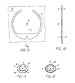
- Figure 9 is an enlarged plan view of a further modified safety vent membrane, disclosing a piercing point on one face thereof;
- Figure 10 is a cross-sectional view of the membrane of Figure 9 taken in a plane through line 10-10 of Figure 9;
- Figure 11 is a perspective view of one face of a cover for a hermetically sealed container, in accordance with Figures 9 and 10; and
- Figure 12 is a perspective view of the other face of a cover for a hermetically sealed container, in accordance with Figures 9 and 10.
- Referring to Figure 1 of the drawings, a
strip 2 of material is fed from asupply zone 3 where it can be stored in the form of a coil to a printing zone 4. Thestrip 2 of coiled material can be any one of a number of known materials used in the manufacture of covers for hermetically sealed containers, which is responsive to the hereinafter described controlled etching processes and, in the manufacture of battery covers such as those utilized for hermetically sealed batteries of the button type, a suitable metallic alloy such as cold rolled alloyed carbon steel (for example "C1010") having a thickness in the range of 0.20 to 1.52 mm (0.008 to 0.06 inches), and, advantageously, approximately 0.50 mm (0.020 inches) plus or minus 0.05 mm (0.002 inches) can be used. It is to be understood that prior to carrying out the etching process, an appropriate cleaning and degreasing of the metallic alloy can be accomplished in a satisfactory cleansing and degreasing bath (not shown). - In the event a metallic steel alloy strip is used, as in the example hereinafter described, a suitable bath using a caustic cleansing agent would suffice.
- In printing zone 4, opposed printing rolls 6, frequently or continuously treated with a suitable masking resist agent or etching ground which can be selected from appropriate chemical materials in accordance with the material to be etched and the subsequent chemicals to be used in the etching process, mask all surfaces of the strip of material not to be etched with an appropriate etching resist coating, for example, a synthetic resin capable of resisting the particular etching step to be employed.
- The unmasked portion of the strip of material to which no resist coating has been applied in printing zone 4 by rolls 6 can be in any one of several geometric pattern forms in accordance with the present invention. In the embodiment of Figures 2 and 3, the geometric pattern includes spaced uncovered channel areas in the form of
circular arcs 7 of less than 360 degrees, with a portion of each otherwise complete circle being masked to provide a retention portion. In the embodiment of Figures 4-12, each of thecircular arcs 7 surrounds an uncovered hole definingcentral area 8 on at least one surface thereof and in the embodiments of Figures 5-8, thearcs 7 are on opposite surfaces ofmaterial strips 2 in opposed mirror image relationship. In Figures 9-12, the geometric pattern of unmasked mirror imagecircular arcs 7 on opposite surfaces of the strip ofmaterial 2, each include an enlargedunmasked chord section 9 located at the base of the arc. It is to be noted that one surface of the strip ofmaterial 2 in the Figures 9-12 also includes a triangular resist mask area that extends intochord section 9 of eachchannel 7 so that upon etching eachchannel 7 on one side incorporates asharp piercing point 11 therein.Piercing point 11 is geometrically disposed opposite to the masked covered retention portion of the otherwise circle definingcircular arc 7 so as to facilitate tearing and retention of the torn portion when preselected pressure on the etched portion of the cover is exceeded. - Referring to Figure 5, it can be seen that a plurality of
unmasked channels 7 can be positioned onstrip 2 in any one of a number of different geometric orientations, depending upon material grains and the results desired. In the embodiment of Figure 5, each of the horse-shoe shapedchannels 7 in the lower half ofstrip 2 are shown as oriented in a position which is at 90 degrees to the horse-shoe shapedchannels 7 in the upper half of thestrip 2 for purposes of illustration. It is to be understood that other positions can also be utilized and that, generally, all channels on a strip are oriented in a similarly selected position. As also will be noted in Figure 5,strip 2 can be in the form of individual sheets rather than a continuous coil as disclosed in Figure 1. - In accordance with the inventive process and again referring to Figure 1, after
strip 2 has been suitably masked with a resist coating in the manner above discussed,strip 2 is fed along spacedidle rollers 10 through anetching zone 12, arinsing zone 13, alubricating zone 14 and finally a stamping or forming zone 16 where individual container covers 17, such as disclosed in Figures 4, 8, 11 and 12, are formed. It is to be understood thatstrip 2, after passing throughrinsing zone 13, could be again coiled for subsequent treatment elsewhere. It, also, is to be noted that various types ofrims 20 can be formed oncovers 17 or rims can be eliminated, if so desired. - In passing through
zones strip 2 is fed along suitableidle rollers 10, as above noted. Inetching zone 12,strip 2 can be fed through a suitable acid etching bath, such as ferric chloride if the material to be etched is a steel alloy. The density and temperature of the etching bath and even the number of baths can be controlled to avoid gas bubbling. Also, such parameters as the rate of feed or residence time of the strip within the bath or baths, the acidity concentrations of the bath and bath temperatures are all carefully controlled so that the etching depth and thus the thickness of the material is carefully predetermined and maintained uniform along the unmasked surfaces. For example, when a steel alloy of 0.50 mm (0.020 inches) is used, the etching is controlled to provide a uniform membrane thickness in the range of 0.02 to 0.101 mm (0.001 to 0.004 inches) plus or minus 0.005 mm (0.0002 inches) throughout the uncovered area. It is to be understood that advantageously, when battery covers for hermetically sealed containers are being processed, the depth of etching is so controlled as to leave safety membranes of metal thickness capable of withstanding a preselected pressure within the sealed containers of which such covers form a part in the range of approximately 0.34 to approximately 3.10 MPa (approximately 50 to approximately 450 pounds per square inch) before the safety membranes rupture. - Once
strip 2 has been properly etched inetching zone 12, it is then fed throughrinsing zone 13. In the inventive embodiment of Figure 1,rinsing zone 13 can include three stages, namely, a neutralizingstage 18, a resiststripping stage 19 and awashing stage 21. The neutralizingstage 18 can include a bath of suitable caustic or alkaline solution such as sodium hydroxide. - The stripping stage can include an appropriate acidic bath depending upon the chemistry of the mask resist coating applied to printing rolls 6 in printing zone 4 and the
washing stage 21 can be a plain tap water bath. From the last stage ofrinsing zone 13,strip 2 can be fed to a suitable oil lubricatingzone 14 before it is fed into a forming or stamping zone 16 to formcovers 17 fromstrip 2. As inetching zone 12, the residence times and bath concentrations in therinsing zone 13,stages - As aforenoted, it is to be understood that various changes can be made in the several steps of the method and product disclosed without departing from the invention. For example, other covers besides those for hermetically sealed containers can be so manufactured and other container materials besides steel alloys can be used in the inventive process and the etching treatments and channel geometries can be varied to provide safety membranes which will accommodate other predetermined pressures for containers.
Claims (7)
Priority Applications (1)
| Application Number | Priority Date | Filing Date | Title |
|---|---|---|---|
| AT86630145T ATE52816T1 (en) | 1985-09-30 | 1986-09-29 | SAFETY CAP WITH OUTFLOW MEANS FOR SELF CONTAINERS AND PROCESS FOR ITS MANUFACTURE. |
Applications Claiming Priority (2)
| Application Number | Priority Date | Filing Date | Title |
|---|---|---|---|
| US78204885A | 1985-09-30 | 1985-09-30 | |
| US782048 | 1985-09-30 |
Publications (2)
| Publication Number | Publication Date |
|---|---|
| EP0217725A1 EP0217725A1 (en) | 1987-04-08 |
| EP0217725B1 true EP0217725B1 (en) | 1990-05-16 |
Family
ID=25124793
Family Applications (1)
| Application Number | Title | Priority Date | Filing Date |
|---|---|---|---|
| EP86630145A Expired - Lifetime EP0217725B1 (en) | 1985-09-30 | 1986-09-29 | Safety vented cover for sealed container and method of manufacturing same |
Country Status (13)
| Country | Link |
|---|---|
| EP (1) | EP0217725B1 (en) |
| JP (1) | JPS6297256A (en) |
| KR (1) | KR910007158B1 (en) |
| CN (1) | CN1016712B (en) |
| AT (1) | ATE52816T1 (en) |
| AU (1) | AU590611B2 (en) |
| BR (1) | BR8604254A (en) |
| DE (1) | DE3671251D1 (en) |
| DK (1) | DK462186A (en) |
| HK (1) | HK891A (en) |
| IL (1) | IL79994A (en) |
| MX (1) | MX168738B (en) |
| SG (1) | SG63190G (en) |
Families Citing this family (13)
| Publication number | Priority date | Publication date | Assignee | Title |
|---|---|---|---|---|
| IL83406A (en) * | 1986-09-19 | 1991-07-18 | Emerson Electric Co | Modified safety vented cover for sealed container and method of manufacturing same |
| DE3728546A1 (en) * | 1987-08-27 | 1989-03-09 | Sonnenschein Lithium Gmbh | PRESSURE VESSEL |
| CA2041062C (en) * | 1991-02-14 | 2000-11-28 | D. Gregory Beckett | Demetallizing procedure |
| TW373348B (en) | 1997-05-09 | 1999-11-01 | Toyo Kohan Co Ltd | Closed battery and closing member |
| MY124164A (en) * | 1997-05-09 | 2006-06-30 | Fukuda Metal Foil Powder | Closed battery and closing member |
| JPH11144705A (en) | 1997-11-11 | 1999-05-28 | Matsushita Electric Ind Co Ltd | Explosion-proof non-aqueous electrolyte secondary battery and method for setting its rupture pressure |
| GB2334812A (en) * | 1998-02-27 | 1999-09-01 | Motorola Betriebsfunk Berlin G | Battery housing |
| USRE38518E1 (en) | 1998-08-21 | 2004-05-18 | Eveready Battery Company, Inc. | Battery constructions having increased internal volume for active components |
| US6265101B1 (en) | 1998-08-21 | 2001-07-24 | Eveready Battery Company, Inc. | Battery constructions having increased internal volume for active components |
| US6294283B1 (en) | 1998-08-21 | 2001-09-25 | Eveready Battery Company, Inc. | Electrochemical cell having low profile seal assembly |
| US6632558B1 (en) | 1998-08-21 | 2003-10-14 | Eveready Battery Company, Inc. | Battery construction having pressure release mechanism |
| GB201214716D0 (en) * | 2012-08-17 | 2012-10-03 | Crown Packaging Technology Inc | Metal cans with peelable lids |
| CN111740065A (en) * | 2020-07-15 | 2020-10-02 | 池州市骏智机电科技有限公司 | A kind of power battery explosion-proof valve with stable structure and its processing technology |
Family Cites Families (8)
| Publication number | Priority date | Publication date | Assignee | Title |
|---|---|---|---|---|
| US3723269A (en) * | 1971-04-06 | 1973-03-27 | Alusuisse | Method of producing tearing lines in metal containers |
| CH552520A (en) * | 1971-06-23 | 1974-08-15 | Alusuisse | SAFETY BOX INTENDED TO CONTAIN A FLUID UNDER PRESSURE. |
| AT322438B (en) * | 1972-09-25 | 1975-05-26 | Hoell Metallwarenfab Karl | CONTAINER FOR RECEIVING PRESSURIZED MEDIA |
| US4122595A (en) * | 1977-08-12 | 1978-10-31 | Black, Sivalls & Bryson, Inc. | Scored rupture disk manufacturing method |
| DE2941749A1 (en) * | 1979-10-16 | 1981-04-30 | Varta Batterie Ag, 3000 Hannover | Electrolytic battery cell with pressure burst section - has relief section in cover in shape of plus sign |
| JPS58210169A (en) * | 1982-06-02 | 1983-12-07 | Kyodo Printing Co Ltd | Production of etched article |
| JPH0612451B2 (en) * | 1982-10-14 | 1994-02-16 | 株式会社東芝 | Corrosion resistant photosensitive film |
| JPS5979965A (en) * | 1982-10-28 | 1984-05-09 | Japan Storage Battery Co Ltd | Thionyl chloride-lithium cell |
-
1986
- 1986-09-04 BR BR8604254A patent/BR8604254A/en not_active IP Right Cessation
- 1986-09-05 AU AU62504/86A patent/AU590611B2/en not_active Ceased
- 1986-09-09 IL IL79994A patent/IL79994A/en not_active IP Right Cessation
- 1986-09-27 CN CN86106513A patent/CN1016712B/en not_active Expired
- 1986-09-29 AT AT86630145T patent/ATE52816T1/en not_active IP Right Cessation
- 1986-09-29 DK DK462186A patent/DK462186A/en not_active Application Discontinuation
- 1986-09-29 EP EP86630145A patent/EP0217725B1/en not_active Expired - Lifetime
- 1986-09-29 KR KR1019860008135A patent/KR910007158B1/en not_active Expired
- 1986-09-29 DE DE8686630145T patent/DE3671251D1/en not_active Expired - Lifetime
- 1986-09-30 JP JP61233132A patent/JPS6297256A/en active Pending
- 1986-09-30 MX MX003887A patent/MX168738B/en unknown
-
1990
- 1990-07-31 SG SG631/90A patent/SG63190G/en unknown
-
1991
- 1991-01-03 HK HK8/91A patent/HK891A/en not_active IP Right Cessation
Also Published As
| Publication number | Publication date |
|---|---|
| AU6250486A (en) | 1987-04-02 |
| KR910007158B1 (en) | 1991-09-18 |
| IL79994A0 (en) | 1986-12-31 |
| IL79994A (en) | 1991-07-18 |
| KR870002992A (en) | 1987-04-14 |
| HK891A (en) | 1991-01-11 |
| BR8604254A (en) | 1987-04-28 |
| JPS6297256A (en) | 1987-05-06 |
| CN86106513A (en) | 1987-04-01 |
| EP0217725A1 (en) | 1987-04-08 |
| DK462186A (en) | 1987-03-31 |
| DK462186D0 (en) | 1986-09-29 |
| AU590611B2 (en) | 1989-11-09 |
| MX168738B (en) | 1993-06-07 |
| CN1016712B (en) | 1992-05-20 |
| DE3671251D1 (en) | 1990-06-21 |
| SG63190G (en) | 1990-11-23 |
| ATE52816T1 (en) | 1990-06-15 |
Similar Documents
| Publication | Publication Date | Title |
|---|---|---|
| US4803136A (en) | Method of manufacturing a safety vented container and product | |
| EP0217725B1 (en) | Safety vented cover for sealed container and method of manufacturing same | |
| EP0262070B1 (en) | Modified safety vented cover for sealed container and method of manufacturing same | |
| US7600527B2 (en) | Reverse acting rupture disc with laser-defined electropolished line of weakness and method of forming the line of weakness | |
| US4122595A (en) | Scored rupture disk manufacturing method | |
| US4829319A (en) | Plastic orifice plate for an ink jet printhead and method of manufacture | |
| DE69715600T2 (en) | Coated material for a pressure relief valve | |
| KR930702087A (en) | Manufacturing method of steel sheet and dull rolling roll with excellent paint clarity and press formability | |
| US3723269A (en) | Method of producing tearing lines in metal containers | |
| JPH10172529A (en) | Manufacturing method of explosion-proof safety pieces for batteries | |
| US3563819A (en) | Mechanochemical sheet metal blanking system | |
| US3245851A (en) | Method of patterning metal surfaces | |
| US3654023A (en) | Mechanochemical sheet metal blanking system | |
| GB2102707A (en) | Manufacture of anti-slip decking | |
| SU1337155A1 (en) | Method of rolling lithium | |
| US3764276A (en) | Mechanochemical sheet metal blanking system | |
| JPH03297053A (en) | Manufacture of sealed cell | |
| HK1174885B (en) | Method of forming a reverse acting rupture disc with laser-defined electropolished line of weakness | |
| HK1120096B (en) | Reverse acting rupture disc with laser-defined electropolished line of weakness and method of forming the line of weakness | |
| DE1929033A1 (en) | Printed circuits and printed cable forms | |
| JPS56158234A (en) | Production of handle for can | |
| JPH0394080A (en) | Production of high friction roller |
Legal Events
| Date | Code | Title | Description |
|---|---|---|---|
| PUAI | Public reference made under article 153(3) epc to a published international application that has entered the european phase |
Free format text: ORIGINAL CODE: 0009012 |
|
| AK | Designated contracting states |
Kind code of ref document: A1 Designated state(s): AT CH DE FR GB IT LI NL |
|
| 17P | Request for examination filed |
Effective date: 19870819 |
|
| 17Q | First examination report despatched |
Effective date: 19880928 |
|
| GRAA | (expected) grant |
Free format text: ORIGINAL CODE: 0009210 |
|
| AK | Designated contracting states |
Kind code of ref document: B1 Designated state(s): AT CH DE FR GB IT LI NL |
|
| REF | Corresponds to: |
Ref document number: 52816 Country of ref document: AT Date of ref document: 19900615 Kind code of ref document: T |
|
| ET | Fr: translation filed | ||
| REF | Corresponds to: |
Ref document number: 3671251 Country of ref document: DE Date of ref document: 19900621 |
|
| ITF | It: translation for a ep patent filed | ||
| PLBE | No opposition filed within time limit |
Free format text: ORIGINAL CODE: 0009261 |
|
| STAA | Information on the status of an ep patent application or granted ep patent |
Free format text: STATUS: NO OPPOSITION FILED WITHIN TIME LIMIT |
|
| 26N | No opposition filed | ||
| ITTA | It: last paid annual fee | ||
| REG | Reference to a national code |
Ref country code: GB Ref legal event code: IF02 |
|
| PGFP | Annual fee paid to national office [announced via postgrant information from national office to epo] |
Ref country code: AT Payment date: 20030902 Year of fee payment: 18 |
|
| PGFP | Annual fee paid to national office [announced via postgrant information from national office to epo] |
Ref country code: FR Payment date: 20030918 Year of fee payment: 18 |
|
| PGFP | Annual fee paid to national office [announced via postgrant information from national office to epo] |
Ref country code: DE Payment date: 20031031 Year of fee payment: 18 |
|
| PGFP | Annual fee paid to national office [announced via postgrant information from national office to epo] |
Ref country code: NL Payment date: 20040829 Year of fee payment: 19 |
|
| PGFP | Annual fee paid to national office [announced via postgrant information from national office to epo] |
Ref country code: GB Payment date: 20040922 Year of fee payment: 19 |
|
| PGFP | Annual fee paid to national office [announced via postgrant information from national office to epo] |
Ref country code: CH Payment date: 20040924 Year of fee payment: 19 |
|
| PG25 | Lapsed in a contracting state [announced via postgrant information from national office to epo] |
Ref country code: AT Free format text: LAPSE BECAUSE OF NON-PAYMENT OF DUE FEES Effective date: 20040929 |
|
| PG25 | Lapsed in a contracting state [announced via postgrant information from national office to epo] |
Ref country code: DE Free format text: LAPSE BECAUSE OF NON-PAYMENT OF DUE FEES Effective date: 20050401 |
|
| PG25 | Lapsed in a contracting state [announced via postgrant information from national office to epo] |
Ref country code: FR Free format text: LAPSE BECAUSE OF NON-PAYMENT OF DUE FEES Effective date: 20050531 |
|
| REG | Reference to a national code |
Ref country code: FR Ref legal event code: ST |
|
| PG25 | Lapsed in a contracting state [announced via postgrant information from national office to epo] |
Ref country code: IT Free format text: LAPSE BECAUSE OF NON-PAYMENT OF DUE FEES;WARNING: LAPSES OF ITALIAN PATENTS WITH EFFECTIVE DATE BEFORE 2007 MAY HAVE OCCURRED AT ANY TIME BEFORE 2007. THE CORRECT EFFECTIVE DATE MAY BE DIFFERENT FROM THE ONE RECORDED. Effective date: 20050929 Ref country code: GB Free format text: LAPSE BECAUSE OF NON-PAYMENT OF DUE FEES Effective date: 20050929 |
|
| PG25 | Lapsed in a contracting state [announced via postgrant information from national office to epo] |
Ref country code: LI Free format text: LAPSE BECAUSE OF NON-PAYMENT OF DUE FEES Effective date: 20050930 Ref country code: CH Free format text: LAPSE BECAUSE OF NON-PAYMENT OF DUE FEES Effective date: 20050930 |
|
| PG25 | Lapsed in a contracting state [announced via postgrant information from national office to epo] |
Ref country code: NL Free format text: LAPSE BECAUSE OF NON-PAYMENT OF DUE FEES Effective date: 20060401 |
|
| REG | Reference to a national code |
Ref country code: CH Ref legal event code: PL |
|
| GBPC | Gb: european patent ceased through non-payment of renewal fee |
Effective date: 20050929 |
|
| NLV4 | Nl: lapsed or anulled due to non-payment of the annual fee |
Effective date: 20060401 |