EP0216514A1 - Electromagnetic clutches - Google Patents
Electromagnetic clutches Download PDFInfo
- Publication number
- EP0216514A1 EP0216514A1 EP86306515A EP86306515A EP0216514A1 EP 0216514 A1 EP0216514 A1 EP 0216514A1 EP 86306515 A EP86306515 A EP 86306515A EP 86306515 A EP86306515 A EP 86306515A EP 0216514 A1 EP0216514 A1 EP 0216514A1
- Authority
- EP
- European Patent Office
- Prior art keywords
- rotor
- projections
- armature plate
- electromagnetic clutch
- frictional surfaces
- Prior art date
- Legal status (The legal status is an assumption and is not a legal conclusion. Google has not performed a legal analysis and makes no representation as to the accuracy of the status listed.)
- Granted
Links
- 238000007747 plating Methods 0.000 claims abstract description 28
- 239000002184 metal Substances 0.000 claims abstract description 18
- 229910052751 metal Inorganic materials 0.000 claims abstract description 18
- 239000000696 magnetic material Substances 0.000 claims abstract description 7
- HCHKCACWOHOZIP-UHFFFAOYSA-N Zinc Chemical compound [Zn] HCHKCACWOHOZIP-UHFFFAOYSA-N 0.000 claims description 4
- 229910052725 zinc Inorganic materials 0.000 claims description 4
- 239000011701 zinc Substances 0.000 claims description 4
- ATJFFYVFTNAWJD-UHFFFAOYSA-N Tin Chemical compound [Sn] ATJFFYVFTNAWJD-UHFFFAOYSA-N 0.000 claims description 3
- 238000005246 galvanizing Methods 0.000 claims description 3
- 230000001464 adherent effect Effects 0.000 description 10
- 230000005540 biological transmission Effects 0.000 description 7
- 230000003247 decreasing effect Effects 0.000 description 4
- 238000010276 construction Methods 0.000 description 3
- 230000004907 flux Effects 0.000 description 3
- 238000003754 machining Methods 0.000 description 3
- 229910000831 Steel Inorganic materials 0.000 description 2
- 239000003507 refrigerant Substances 0.000 description 2
- 239000010959 steel Substances 0.000 description 2
- 229910001128 Sn alloy Inorganic materials 0.000 description 1
- 229910001297 Zn alloy Inorganic materials 0.000 description 1
- 238000005299 abrasion Methods 0.000 description 1
- 238000004378 air conditioning Methods 0.000 description 1
- 238000005552 hardfacing Methods 0.000 description 1
- 238000010438 heat treatment Methods 0.000 description 1
- 230000001788 irregular Effects 0.000 description 1
- 239000000463 material Substances 0.000 description 1
- 239000011135 tin Substances 0.000 description 1
Images
Classifications
-
- F—MECHANICAL ENGINEERING; LIGHTING; HEATING; WEAPONS; BLASTING
- F16—ENGINEERING ELEMENTS AND UNITS; GENERAL MEASURES FOR PRODUCING AND MAINTAINING EFFECTIVE FUNCTIONING OF MACHINES OR INSTALLATIONS; THERMAL INSULATION IN GENERAL
- F16D—COUPLINGS FOR TRANSMITTING ROTATION; CLUTCHES; BRAKES
- F16D27/00—Magnetically- or electrically- actuated clutches; Control or electric circuits therefor
- F16D27/10—Magnetically- or electrically- actuated clutches; Control or electric circuits therefor with an electromagnet not rotating with a clutching member, i.e. without collecting rings
- F16D27/108—Magnetically- or electrically- actuated clutches; Control or electric circuits therefor with an electromagnet not rotating with a clutching member, i.e. without collecting rings with axially movable clutching members
- F16D27/112—Magnetically- or electrically- actuated clutches; Control or electric circuits therefor with an electromagnet not rotating with a clutching member, i.e. without collecting rings with axially movable clutching members with flat friction surfaces, e.g. discs
-
- F—MECHANICAL ENGINEERING; LIGHTING; HEATING; WEAPONS; BLASTING
- F16—ENGINEERING ELEMENTS AND UNITS; GENERAL MEASURES FOR PRODUCING AND MAINTAINING EFFECTIVE FUNCTIONING OF MACHINES OR INSTALLATIONS; THERMAL INSULATION IN GENERAL
- F16D—COUPLINGS FOR TRANSMITTING ROTATION; CLUTCHES; BRAKES
- F16D27/00—Magnetically- or electrically- actuated clutches; Control or electric circuits therefor
- F16D27/14—Details
-
- F—MECHANICAL ENGINEERING; LIGHTING; HEATING; WEAPONS; BLASTING
- F16—ENGINEERING ELEMENTS AND UNITS; GENERAL MEASURES FOR PRODUCING AND MAINTAINING EFFECTIVE FUNCTIONING OF MACHINES OR INSTALLATIONS; THERMAL INSULATION IN GENERAL
- F16D—COUPLINGS FOR TRANSMITTING ROTATION; CLUTCHES; BRAKES
- F16D2300/00—Special features for couplings or clutches
- F16D2300/10—Surface characteristics; Details related to material surfaces
Definitions
- This invention relates to electromagnetic clutches, and more particularly, relates to frictional surfaces for rotatable members of the electromagnetic clutches.
- Electromagnetic clutches are well known in the prior art and are often used for controlling the transfer of power from an automobile engine to the refrigerant compressor of an automobile air conditioning system.
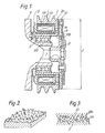
- Figure l being a cross-sectional view showing an electromagnetic clutch l mounted on a refrigerant compressor housing 3.
- the electromagnetic clutch l has a ring-shaped rotor 2 rotatably supported on tubular projecting portion 3a of the compressor housing 3 through radial bearing 4.
- An electromagnet 5 is stationarily disposed in hollow portion 6 which is formed in rotor 2 and fixed on the compressor housing 3 by means of bolts.
- Electromagnet 5 comprises annular U-shaped housing 5a and electromagnetic coil 5b contained in housing 5a.
- Drive shaft 7 is rotatably supported in compressor housing 3 through a radial bearing (not shown) which is mounted in tubular projecting portion 3a.
- Hub 8 is secured on the outer end of drive shaft 7 which extends from tubular projecting portion 3a and connected to ring-shaped armature plate l0 through a plurality of leaf springs 9.
- Armature plate l0 is thus supported by leaf springs 9 around hub 8 with a radial gap and faces annular pole faces 2a of rotor 2 with an axial gap.
- Armature plate l0 may be disposed between rotor 2 and a flange portion on hub 8.
- armature plate l0 is provided with concentric annular magnetic pole faces l0a.
- a frictional surface defined by pole faces 2a of rotor 2 and a frictional surface defined by pole faces l0a of armature plate l0 are formed by turning, and then plated and thereafter treated by grinding. These frictional surfaces are thus provided with irregular depressions and projections as shown in Figure 2.
- the materials of the frictional surfaces have the same hardness. Therefore, if there is only partial contact between the frictional surfaces in the initial stage of engagement in an electromagnetic clutch, a weld deposit with high hardness is formed between the frictional surfaces. The frictional surfaces become rough.
- Possible solutions to obtain large torque transfer in the initial stage of engagement, such as below fifty times, are to enlarge the area of the frictional surfaces by increasing dimension D in Figure l, or to increase the magnetic force by enlarging the sectional area of coil 5b, but these solutions increase the size and weight of the electromagnetic clutch.
- the rotor or armature plate has a thin layer made of soft metal, which is softer and has a higher frictional factor than magnetic material forming both frictional surfaces.
- An electromagnetic clutch comprises a first rotatable member rotatably supported on a bearing, said first rotatable member having an axial end magnetic frictional surface, a second rotatable member rotatably supported on a second bearing, an annular magnetic armature member supported on said second rotatable member so as to be capable of limited axial movement, and having an axial end magnetic frictional surface which faces said axial end magnetic frictional surface of said first rotatable member with an axial gap therebetween, and electromagnetic means for attracting the facing frictional surfaces into contact with one another, characterised in that at least one of said facing frictional surfaces of said first rotatable member and said armature member is provided with spirally curved depressions and projections with a predetermined pitch and further provided with a layer of metal plating with lower hardness than the magnetic materials of said rotatable member and said armature member.
- the electromagnetic clutch of this invention can have a high level of torque transfer, can be compact and light in weight, and can at the same time be low in cost and high in effectiveness.
- Said layer of metal plating can be galvanising, or said layer of metal plating can be tin and zinc plating.
- both of said facing frictional surfaces are provided with said spirally curved depressions and projections, but only one of said facing frictional surfaces is further provided with said layer of metal plating.
- either one of said facing frictional surfaces is provided with said spirally curved depressions and projections and further provided with said layer of metal plating, the other of said facing frictional surfaces being provided with a plurality of irregularly formed small depressions and projections.
- Said irregularly formed small depressions and projections may be formed by grinding or pressing.
- rotor 2 is formed of an integrated body of magnetic material, such as steel, and comprises inner cylindrical portion 2l, outer cylindrical portion 22 and end plate portion 23 which is connected at an axial end of the rotor 2 between both cylindrical portions 2l and 22.
- End plate portion 23 is provided with a plurality of concentric slits 23a,23b. These slits form between them concentric annular magnetic pole faces 2a which define a frictional surface.
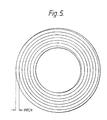
- the frictional surface of pole faces 2a of rotor 2 is finished by machining and is then plated.
- the front end view of the frictional surface of a pole face 2a after machining is shown in Figure 5, i.e. small spirally curved depressions and projections are formed on the frictional surface of pole faces 2a of rotor 2 which face armature plate l0.
- Rotor 2 is then disposed in a plating tank to form a layer of plating.
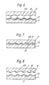
- layer l3 of plating is formed on frictional surface of pole faces 2a, as shown in Figure 6.
- Layer l3 of plating may be treated on the surface by electric zinc galvanising, and has forty five degree as Brinell hardness.
- Armature plate l0 is also formed of magnetic material, such as steel plates, and has sixty two degree as Brinell hardness. Similar spirally curved depressions and projections are formed on the frictional surface of the pole faces l0a of armature plate l0.
- the spirally curved depressions and projections formed on rotor 2 and armature plate l0 have a certain interval, or predetermined pitch, e.g. from 0.3 mm to 0.5 mm, and extend in the same spiral direction as each other.
- the depressions and projections are easily formed by machining.
- Adherent portion ll and shaved off portion l2 are formed on the same circumference at several locations which face each other, and also are formed arc-shaped. Adherent portion ll and shaved off portion l2 are formed on initial engagement. Adherent portion ll and shaved off portion l2 produce sufficient frictional force to prevent the decreasing of transmission torque even though attractive force to armature plate l0 is lessened by decreasing the magnetic force. Therefore, after armature plate l0 has been attracted to rotor 2, the volume of electric current supplied to coil 5b of electromagnet 5 may be decreased.
- the reason for increase of transmission torque is that adherent portion ll and shaved off portion l2 are made by forcedly tearing the same body off, the engagement between adherent portion ll and shaved off portion l2 maintaining close contact.
- adherent portion ll and shaved off portion l2 are engaged with one another, resistance force against this tearing is added to the frictional force between adherent portion ll and shaved off portion l2, and thus the transmission torque is made large.
- the transmission torque of electromagnetic clutch is not affected by the co-efficient of friction of the plating metal. Therefore, a plating metal which has lower hardness and is more inexpensive than magnetic materials should be utilised, e.g. zinc, or tin and zinc alloy.
- transmission torque of this invention is equal to that of a conventional embodiment.
- a deposit is produced on the frictional surfaces of rotor 2 and armature plate l0 within fifty times of engagement, and hard facing and failure by heating may be produced.
- adherent portions of the plating metal are dispersedly produced between the frictional surfaces of rotor 2 and armature plate l0. Transmission torque is thus surely increased by the adherent portions.
- the direction of the spirally curved depressions and projections of rotor 2 may be the same as the direction of rotation of rotor 2 or be opposite to the direction of rotation of rotor 2. Also, the direction of the spirally curved depressions and projections of rotor 2 and armature plate l0 may be opposite each other.
- electromagnetic clutches of the present invention are not restricted to the embodiments described hereinabove, for example the electromagnet could be re-located to be associated with the armature plate rather than the rotor.
Landscapes
- Engineering & Computer Science (AREA)
- General Engineering & Computer Science (AREA)
- Mechanical Engineering (AREA)
- Physics & Mathematics (AREA)
- Electromagnetism (AREA)
- Mechanical Operated Clutches (AREA)
- Braking Arrangements (AREA)
Abstract
Description
- This invention relates to electromagnetic clutches, and more particularly, relates to frictional surfaces for rotatable members of the electromagnetic clutches.
- Electromagnetic clutches are well known in the prior art and are often used for controlling the transfer of power from an automobile engine to the refrigerant compressor of an automobile air conditioning system.
- With reference to Figure l, an electromagnetic clutch of the type in the prior art will be described, Figure l being a cross-sectional view showing an electromagnetic clutch l mounted on a
refrigerant compressor housing 3. - The electromagnetic clutch l has a ring-
shaped rotor 2 rotatably supported on tubular projecting portion 3a of thecompressor housing 3 throughradial bearing 4. Anelectromagnet 5 is stationarily disposed in hollow portion 6 which is formed inrotor 2 and fixed on thecompressor housing 3 by means of bolts.Electromagnet 5 comprises annular U-shaped housing 5a and electromagnetic coil 5b contained in housing 5a. -
Drive shaft 7 is rotatably supported incompressor housing 3 through a radial bearing (not shown) which is mounted in tubular projecting portion 3a.Hub 8 is secured on the outer end ofdrive shaft 7 which extends from tubular projecting portion 3a and connected to ring-shaped armature plate l0 through a plurality ofleaf springs 9. Armature plate l0 is thus supported byleaf springs 9 aroundhub 8 with a radial gap and faces annular pole faces 2a ofrotor 2 with an axial gap. Armature plate l0 may be disposed betweenrotor 2 and a flange portion onhub 8. Also armature plate l0 is provided with concentric annular magnetic pole faces l0a. - In this construction of electromagnetic clutch, when coil 5b of
electromagnet 5 is energised, magnetic flux is generated and passed through annular housing 5a,rotor 2, armature plate l0,rotor 2 and housing 5a. Armature plate l0 is thus attracted to pole faces 2a ofrotor 2. Accordingly, the rotational force ofrotor 2 is transmitted to driveshaft 7 through armature plate l0. On the other hand, when coil 5b ofelectromagnet 5 is de-energised, the magnetic flux disappears, and armature plate l0 is disconnected from pole faces 2a ofrotor 2 by recoil strength ofleaf springs 9. Therefore, the rotational force ofrotor 2 is not transmitted to driveshaft 7. - In the above-mentioned electromagnetic clutch, a frictional surface defined by pole faces 2a of
rotor 2 and a frictional surface defined by pole faces l0a of armature plate l0 are formed by turning, and then plated and thereafter treated by grinding. These frictional surfaces are thus provided with irregular depressions and projections as shown in Figure 2. The initial contact area between theopposed rotor 2 and armature plate l0, when their frictional surfaces are produced by grinding, is only below twenty percent of their potential area of contact. - Referring to Figure 3, when the frictional surfaces of
rotor 2 and armature plate l0 are initially engaged with one another, wedge-shaped projection 2b ofrotor 2 and wedge-shaped projection l0b of armature plate l0 scratch each other. Therefore, a large frictional force is produced therebetween. However, shears are generated on the top of the projections by engagement ofrotor 2 and armature plate l0. Accordingly, after projections 2b and l0b have been engaged two or three times, the tops of the projections 2b and l0b are shaved away, and the torque transfer is decreased. - Thereafter, the area of contact between
rotor 2 and armature plate l0 is gradually increased by abrasion caused by continuous engagement, and thus the torque transfer of electromagnetic clutch l is increased. Finally, the torque transfer of electromagnetic clutch l becomes three or four times its required (initial) value. However, when the number of engagement time is less than a certain number, e.g. fifty times, the torque transfer of electromagnetic clutch l is not increased. - Also, in general, the materials of the frictional surfaces have the same hardness. Therefore, if there is only partial contact between the frictional surfaces in the initial stage of engagement in an electromagnetic clutch, a weld deposit with high hardness is formed between the frictional surfaces. The frictional surfaces become rough.
- Possible solutions to obtain large torque transfer in the initial stage of engagement, such as below fifty times, are to enlarge the area of the frictional surfaces by increasing dimension D in Figure l, or to increase the magnetic force by enlarging the sectional area of coil 5b, but these solutions increase the size and weight of the electromagnetic clutch.
- A construction for improvement of torque transfer without change of dimension of an electromagnetic clutch is shown in Japanese patent application publication no: 54-l47,345. The rotor or armature plate has a thin layer made of soft metal, which is softer and has a higher frictional factor than magnetic material forming both frictional surfaces.
- An electromagnetic clutch, according to the present invention, comprises a first rotatable member rotatably supported on a bearing, said first rotatable member having an axial end magnetic frictional surface, a second rotatable member rotatably supported on a second bearing, an annular magnetic armature member supported on said second rotatable member so as to be capable of limited axial movement, and having an axial end magnetic frictional surface which faces said axial end magnetic frictional surface of said first rotatable member with an axial gap therebetween, and electromagnetic means for attracting the facing frictional surfaces into contact with one another, characterised in that at least one of said facing frictional surfaces of said first rotatable member and said armature member is provided with spirally curved depressions and projections with a predetermined pitch and further provided with a layer of metal plating with lower hardness than the magnetic materials of said rotatable member and said armature member.
- The electromagnetic clutch of this invention can have a high level of torque transfer, can be compact and light in weight, and can at the same time be low in cost and high in effectiveness.
- Said layer of metal plating can be galvanising, or said layer of metal plating can be tin and zinc plating.
- In one embodiment of the present invention, both of said facing frictional surfaces are provided with said spirally curved depressions and projections, but only one of said facing frictional surfaces is further provided with said layer of metal plating.
- In another embodiment of the present invention, either one of said facing frictional surfaces is provided with said spirally curved depressions and projections and further provided with said layer of metal plating, the other of said facing frictional surfaces being provided with a plurality of irregularly formed small depressions and projections.
- Said irregularly formed small depressions and projections may be formed by grinding or pressing.
- Electromagnetic clutches, according to the present invention, will now be described, by way of example only, with reference to the accompanying drawings, in which:-
- Figure l is a vertical cross sectional view of an electromagnetic clutch known in the prior art;
- Figure 2 is an explanatory rough sketch illustrating a frictional surface of an armature plate or a rotor of the electromagnetic clutch of Figure l;
- Figure 3 is an explanatory cross sectional view illustrating frictional surfaces of an armature plate and a rotor when those are fitted in initial stage in the electromagnetic clutch of Figure l;
- Figure 4 is a vertical cross sectional view of an electromagnetic clutch embodying either embodiment of the present invention;
- Figure 5 is an explanatory front view illustrating a frictional surface of an armature plate or a rotor of a first embodiment of the present invention;
- Figure 6 is an explanatory enlarged cross sectional view illustrating the frictional surfaces of an armature plate and a rotor of the first embodiment of the present invention;
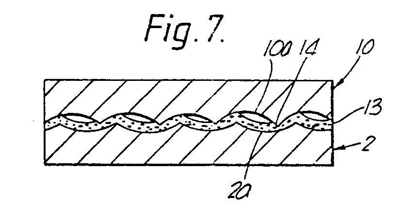
- Figure 7 is an explanatory enlarged cross sectional view illustrating the initial stage of fitting between the frictional surfaces of the armature plate and the rotor of Figure 6;
- Figure 8 is an explanatory enlarged cross sectional view illustrating the result of contact between the frictional surfaces of the armature plate and the rotor of Figure 6;
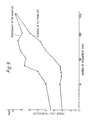
- Figure 9 is a graph which illustrates change of torque transfer corresponding to the engagement times of the rotor and the armature plate in electromagnetic clutches of the prior art and the first embodiment of the present invention;
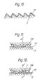
- Figure l0 is an explanatory enlarged cross sectional view illustrating a frictional surface of a rotor of a second embodiment of the present invention;
- Figure ll is an explanatory enlarged cross sectional view illustrating the initial stage of fitting between the frictional surfaces of the armature plate and the rotor of Figure l0;
- Figure l2 is an explanatory enlarged cross sectional view illustrating the result of contact between the frictional surfaces of the armature plate and the rotor of Figure l0; and
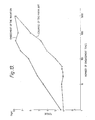
- Figure l3 is a graph which illustrates change of torque transfer corresponding to the engagement times of the rotor and the armature plate in electromagnetic clutches of the prior art and the second embodiment of the present invention.
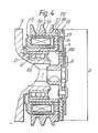
- With reference to Figures 4 and 5, there is shown an electromagnetic clutch of the present invention which is similar to the electromagnetic clutch shown in the Figure l, except for the construction of the rotor and armature plate. Therefore, similar parts are represented by the same reference numbers as shown in Figure l and a detailed description of these parts is omitted.
- In this embodiment of the
present invention rotor 2 is formed of an integrated body of magnetic material, such as steel, and comprises inner cylindrical portion 2l, outer cylindrical portion 22 andend plate portion 23 which is connected at an axial end of therotor 2 between both cylindrical portions 2l and 22.End plate portion 23 is provided with a plurality of concentric slits 23a,23b. These slits form between them concentric annular magnetic pole faces 2a which define a frictional surface. - The frictional surface of pole faces 2a of
rotor 2 is finished by machining and is then plated. The front end view of the frictional surface of a pole face 2a after machining is shown in Figure 5, i.e. small spirally curved depressions and projections are formed on the frictional surface of pole faces 2a ofrotor 2 which face armature plate l0.Rotor 2 is then disposed in a plating tank to form a layer of plating. Thus, layer l3 of plating is formed on frictional surface of pole faces 2a, as shown in Figure 6. Layer l3 of plating may be treated on the surface by electric zinc galvanising, and has forty five degree as Brinell hardness. Armature plate l0 is also formed of magnetic material, such as steel plates, and has sixty two degree as Brinell hardness. Similar spirally curved depressions and projections are formed on the frictional surface of the pole faces l0a of armature plate l0. - The spirally curved depressions and projections formed on
rotor 2 and armature plate l0 have a certain interval, or predetermined pitch, e.g. from 0.3 mm to 0.5 mm, and extend in the same spiral direction as each other. The depressions and projections are easily formed by machining. When magnetic coil 5b is energised, armature plate l0 which is connected withdrive shaft 7 is attracted toaxial end plate 23 and is engaged with the frictional surface of pole faces 2a ofrotor 2 by magnetic flux which is generated by coil 5b ofelectromagnet 5. Thus, driving force is transmitted to driveshaft 7 fromrotor 2 through armature plate l0. - In this operation, when armature plate l0 and
rotor 2 initially engage, as shown in Figure 7, projections l4 formed on frictional surface of pole faces l0a of armature plate l0 gnaw into layer l3 of plating due to attractive force, whereas the projections of layer l3 of plating are deformed and the contact between both frictional surfaces is thus securely close. - Furthermore, when
rotor 2 and armature plate l0 engage each other, layer l3 of plating is partly sloughed off, as shown in Figure 8, and portions ll adhere on the frictional surface of armature plate l0. Adherent portions ll on the armature plate l0 grow due to repeated engagement of armature plate l0 androtor 2. Adhesion means that small projections of the frictional surface of armature plate l0 turn layer l3 of plating on the frictional surface ofrotor 2 thin, the sloughed off metal being locally gathered, pressed, combined and thus coagulated. At the same time, shaved off portions l2 are formed on layer l3 of plating of the frictional surface ofrotor 2. - Adherent portion ll and shaved off portion l2 are formed on the same circumference at several locations which face each other, and also are formed arc-shaped. Adherent portion ll and shaved off portion l2 are formed on initial engagement. Adherent portion ll and shaved off portion l2 produce sufficient frictional force to prevent the decreasing of transmission torque even though attractive force to armature plate l0 is lessened by decreasing the magnetic force. Therefore, after armature plate l0 has been attracted to
rotor 2, the volume of electric current supplied to coil 5b ofelectromagnet 5 may be decreased. The reason for increase of transmission torque is that adherent portion ll and shaved off portion l2 are made by forcedly tearing the same body off, the engagement between adherent portion ll and shaved off portion l2 maintaining close contact. When adherent portion ll and shaved off portion l2 are engaged with one another, resistance force against this tearing is added to the frictional force between adherent portion ll and shaved off portion l2, and thus the transmission torque is made large. - The transmission torque of electromagnetic clutch is not affected by the co-efficient of friction of the plating metal. Therefore, a plating metal which has lower hardness and is more inexpensive than magnetic materials should be utilised, e.g. zinc, or tin and zinc alloy.
- Referring to Figure 9, change of transmission torque within five thousand times of engagement is shown. In the embodiment of this invention, layer l3 of plating on
rotor 2 is shaved off by projections l4 of the frictional surface of armature plate l0, and eventually disappears. Therefore, transmission torque of this invention is equal to that of a conventional embodiment. Also, in a conventional embodiment, a deposit is produced on the frictional surfaces ofrotor 2 and armature plate l0 within fifty times of engagement, and hard facing and failure by heating may be produced. On the other hand, in the electromagnetic clutch of this invention, adherent portions of the plating metal are dispersedly produced between the frictional surfaces ofrotor 2 and armature plate l0. Transmission torque is thus surely increased by the adherent portions. - The direction of the spirally curved depressions and projections of
rotor 2 may be the same as the direction of rotation ofrotor 2 or be opposite to the direction of rotation ofrotor 2. Also, the direction of the spirally curved depressions and projections ofrotor 2 and armature plate l0 may be opposite each other. - A second embodiment of the present invention will now be described with reference to Figures l0 to l3. In fact, the above recited description of the manner of operation of the first embodiment applies equally to the second embodiment, even though in the second embodiment only the
rotor 2 has been formed with the above recited spirally curved depressions and projections. The frictional surface of the pole faces l0a of armature plate l0 in the second embodiment is finished by grinding as in the known prior art. Therefore, a plurality of irregularly formed small depressions and projections l4' are formed on the pole faces l0a. The projections l4' gnaw into the layer l3 of metal plating on therotor 2 in the same manner as outlined hereinbefore. It should be noted, however, that Figures ll and l2 are of an even greater magnification than Figures 6 and 7. - The electromagnetic clutches of the present invention are not restricted to the embodiments described hereinabove, for example the electromagnet could be re-located to be associated with the armature plate rather than the rotor.
Claims (6)
Applications Claiming Priority (4)
| Application Number | Priority Date | Filing Date | Title |
|---|---|---|---|
| JP60184063A JPS6246029A (en) | 1985-08-23 | 1985-08-23 | Electromagnetic clutch |
| JP184063/85 | 1985-08-23 | ||
| JP60186538A JPS6249025A (en) | 1985-08-27 | 1985-08-27 | Electromagnetic clutch |
| JP186538/85 | 1985-08-27 |
Publications (2)
| Publication Number | Publication Date |
|---|---|
| EP0216514A1 true EP0216514A1 (en) | 1987-04-01 |
| EP0216514B1 EP0216514B1 (en) | 1990-11-14 |
Family
ID=26502259
Family Applications (1)
| Application Number | Title | Priority Date | Filing Date |
|---|---|---|---|
| EP19860306515 Expired EP0216514B1 (en) | 1985-08-23 | 1986-08-22 | Electromagnetic clutches |
Country Status (2)
| Country | Link |
|---|---|
| EP (1) | EP0216514B1 (en) |
| DE (1) | DE3675616D1 (en) |
Cited By (5)
| Publication number | Priority date | Publication date | Assignee | Title |
|---|---|---|---|---|
| GB2204649A (en) * | 1987-05-11 | 1988-11-16 | Dana Corp | Soft-start electromagnetic coupling |
| AU754149B2 (en) * | 2000-06-30 | 2002-11-07 | Mitsubishi Heavy Industries, Ltd. | Electromagnetic clutch and compressor equipped therewith |
| WO2010124749A1 (en) * | 2009-04-29 | 2010-11-04 | Kendrion Linnig Gmbh | Electromagnetic friction clutch having oscillating pole faces |
| EP2444684A4 (en) * | 2009-06-18 | 2012-12-12 | Mitsubishi Heavy Ind Ltd | Electromagnetic clutch, compressor, and manufacturing method for electromagnetic clutch |
| DE102014109125A1 (en) * | 2014-06-30 | 2015-12-31 | Kendrion (Villingen) Gmbh | Electromagnetic friction clutch or pole friction brake |
Citations (5)
| Publication number | Priority date | Publication date | Assignee | Title |
|---|---|---|---|---|
| US1519417A (en) * | 1924-03-07 | 1924-12-16 | Clarence Q Payne | Electromagnetic clutch |
| FR934275A (en) * | 1946-09-18 | 1948-05-18 | Improvements to electromechanical clutches | |
| GB691027A (en) * | 1948-07-16 | 1953-05-06 | Hugh Brougham Sedgfield | Improvements in or relating to electromagnetic friction clutches |
| GB792530A (en) * | 1955-07-07 | 1958-03-26 | Ferodo Sa | Improvements in or relating to electro-magnetic clutches |
| US2958406A (en) * | 1958-03-10 | 1960-11-01 | Warner Electric Brake & Clutch | Magnetic torque producing device with lubricated friction faces |
-
1986
- 1986-08-22 DE DE8686306515T patent/DE3675616D1/en not_active Expired - Lifetime
- 1986-08-22 EP EP19860306515 patent/EP0216514B1/en not_active Expired
Patent Citations (5)
| Publication number | Priority date | Publication date | Assignee | Title |
|---|---|---|---|---|
| US1519417A (en) * | 1924-03-07 | 1924-12-16 | Clarence Q Payne | Electromagnetic clutch |
| FR934275A (en) * | 1946-09-18 | 1948-05-18 | Improvements to electromechanical clutches | |
| GB691027A (en) * | 1948-07-16 | 1953-05-06 | Hugh Brougham Sedgfield | Improvements in or relating to electromagnetic friction clutches |
| GB792530A (en) * | 1955-07-07 | 1958-03-26 | Ferodo Sa | Improvements in or relating to electro-magnetic clutches |
| US2958406A (en) * | 1958-03-10 | 1960-11-01 | Warner Electric Brake & Clutch | Magnetic torque producing device with lubricated friction faces |
Non-Patent Citations (1)
| Title |
|---|
| PATENTS ABSTRACTS OF JAPAN, vol. 4, no. 9 (M-89), 23rd January 1980, page 114 M 89; & JP-A-54 147 345 (NIPPON DENSO K.K.) 17-11-1979 (Cat. D,A) * |
Cited By (12)
| Publication number | Priority date | Publication date | Assignee | Title |
|---|---|---|---|---|
| GB2204649A (en) * | 1987-05-11 | 1988-11-16 | Dana Corp | Soft-start electromagnetic coupling |
| DE3815697A1 (en) * | 1987-05-11 | 1988-12-01 | Dana Corp | ELECTROMAGNETIC COUPLING DEVICE, IN PARTICULAR COUPLING |
| FR2616502A1 (en) * | 1987-05-11 | 1988-12-16 | Dana Corp | ELECTROMAGNETIC CLUTCH WITH SOFT START |
| GB2204649B (en) * | 1987-05-11 | 1991-07-10 | Dana Corp | Soft-start electromagnetic coupling |
| DE3815697C2 (en) * | 1987-05-11 | 1998-04-23 | Dana Corp | Electromagnetic coupling device, in particular clutch |
| AU754149B2 (en) * | 2000-06-30 | 2002-11-07 | Mitsubishi Heavy Industries, Ltd. | Electromagnetic clutch and compressor equipped therewith |
| WO2010124749A1 (en) * | 2009-04-29 | 2010-11-04 | Kendrion Linnig Gmbh | Electromagnetic friction clutch having oscillating pole faces |
| US8839931B2 (en) | 2009-04-29 | 2014-09-23 | Kendrion Linnig Gmbh | Electromagnetic friction clutch having oscillating pole faces |
| EP2444684A4 (en) * | 2009-06-18 | 2012-12-12 | Mitsubishi Heavy Ind Ltd | Electromagnetic clutch, compressor, and manufacturing method for electromagnetic clutch |
| US8851259B2 (en) | 2009-06-18 | 2014-10-07 | Mitsubishi Heavy Industries, Ltd. | Electromagnetic clutch, compressor, and manufacturing method for electromagnetic clutch |
| DE102014109125A1 (en) * | 2014-06-30 | 2015-12-31 | Kendrion (Villingen) Gmbh | Electromagnetic friction clutch or pole friction brake |
| DE102014109125B4 (en) * | 2014-06-30 | 2016-09-29 | Kendrion (Villingen) Gmbh | Electromagnetic friction clutch or pole friction brake |
Also Published As
| Publication number | Publication date |
|---|---|
| DE3675616D1 (en) | 1990-12-20 |
| EP0216514B1 (en) | 1990-11-14 |
Similar Documents
| Publication | Publication Date | Title |
|---|---|---|
| EP0947720B1 (en) | Clutch plate | |
| US4705973A (en) | Electromagnetic clutch with spiral plated surfaces to improve frictional contact | |
| US4727974A (en) | Electromagnetic clutch with improved frictional surfaces | |
| EP0422528B1 (en) | Electromagnetic clutch | |
| US4828090A (en) | Electromagnetic clutch | |
| CN102278399B (en) | Braking or clutching device | |
| US5642797A (en) | Molded plastic rotor assembly for electromagnetic friction clutch | |
| EP0216514B1 (en) | Electromagnetic clutches | |
| EP0350789B1 (en) | Electromagnetic clutch | |
| US5059842A (en) | Electromagnetic clutch with grooved friction surface | |
| US4632236A (en) | Electromagnetic clutch having high torque transfer | |
| US5404980A (en) | Electromagnetic clutch with failure protection apparatus | |
| US5232076A (en) | Electromagnetic clutch | |
| EP0339431B1 (en) | Electromagnetic clutch | |
| CA2001393C (en) | Electromagnetic clutch with an adjusting means for adjusting a substantial length of a leaf spring which is for supporting an armature plate | |
| EP0841497A3 (en) | Electromagnetic clutch | |
| EP0175016B1 (en) | Electromagnetic clutch having high torque transfer | |
| US4892176A (en) | Electromagnetic clutch having high torque transfer | |
| CA1316470C (en) | Electromagnetic clutch having a structure for reducing metallic collision and noise | |
| EP0404139B1 (en) | Electromagnetic clutch | |
| JP2001140937A (en) | Electromagnetic coupling device | |
| JPH08219179A (en) | Electromagnetic clutch | |
| JP2594422Y2 (en) | Spring clutch | |
| JPH0629627B2 (en) | Electromagnetic clutch |
Legal Events
| Date | Code | Title | Description |
|---|---|---|---|
| PUAI | Public reference made under article 153(3) epc to a published international application that has entered the european phase |
Free format text: ORIGINAL CODE: 0009012 |
|
| AK | Designated contracting states |
Kind code of ref document: A1 Designated state(s): DE FR GB IT SE |
|
| 17P | Request for examination filed |
Effective date: 19870904 |
|
| 17Q | First examination report despatched |
Effective date: 19880718 |
|
| GRAA | (expected) grant |
Free format text: ORIGINAL CODE: 0009210 |
|
| AK | Designated contracting states |
Kind code of ref document: B1 Designated state(s): DE FR GB IT SE |
|
| ITF | It: translation for a ep patent filed | ||
| ET | Fr: translation filed | ||
| REF | Corresponds to: |
Ref document number: 3675616 Country of ref document: DE Date of ref document: 19901220 |
|
| ITTA | It: last paid annual fee | ||
| PLBE | No opposition filed within time limit |
Free format text: ORIGINAL CODE: 0009261 |
|
| STAA | Information on the status of an ep patent application or granted ep patent |
Free format text: STATUS: NO OPPOSITION FILED WITHIN TIME LIMIT |
|
| 26N | No opposition filed | ||
| EAL | Se: european patent in force in sweden |
Ref document number: 86306515.7 |
|
| REG | Reference to a national code |
Ref country code: GB Ref legal event code: IF02 |
|
| PGFP | Annual fee paid to national office [announced via postgrant information from national office to epo] |
Ref country code: SE Payment date: 20050804 Year of fee payment: 20 |
|
| PGFP | Annual fee paid to national office [announced via postgrant information from national office to epo] |
Ref country code: FR Payment date: 20050809 Year of fee payment: 20 |
|
| PGFP | Annual fee paid to national office [announced via postgrant information from national office to epo] |
Ref country code: GB Payment date: 20050817 Year of fee payment: 20 |
|
| PGFP | Annual fee paid to national office [announced via postgrant information from national office to epo] |
Ref country code: DE Payment date: 20050818 Year of fee payment: 20 |
|
| PGFP | Annual fee paid to national office [announced via postgrant information from national office to epo] |
Ref country code: IT Payment date: 20050829 Year of fee payment: 20 |
|
| PG25 | Lapsed in a contracting state [announced via postgrant information from national office to epo] |
Ref country code: GB Free format text: LAPSE BECAUSE OF EXPIRATION OF PROTECTION Effective date: 20060821 |
|
| REG | Reference to a national code |
Ref country code: GB Ref legal event code: PE20 |
|
| EUG | Se: european patent has lapsed |