EP0216442B1 - Disk drive apparatus - Google Patents
Disk drive apparatus Download PDFInfo
- Publication number
- EP0216442B1 EP0216442B1 EP86304345A EP86304345A EP0216442B1 EP 0216442 B1 EP0216442 B1 EP 0216442B1 EP 86304345 A EP86304345 A EP 86304345A EP 86304345 A EP86304345 A EP 86304345A EP 0216442 B1 EP0216442 B1 EP 0216442B1
- Authority
- EP
- European Patent Office
- Prior art keywords
- disk
- cartridge
- door
- receiver
- housing
- Prior art date
- Legal status (The legal status is an assumption and is not a legal conclusion. Google has not performed a legal analysis and makes no representation as to the accuracy of the status listed.)
- Expired - Lifetime
Links
- 230000037431 insertion Effects 0.000 claims description 13
- 238000003780 insertion Methods 0.000 claims description 13
- 230000001419 dependent effect Effects 0.000 claims description 6
- 230000002441 reversible effect Effects 0.000 claims description 6
- 230000007246 mechanism Effects 0.000 description 8
- 238000001125 extrusion Methods 0.000 description 2
- 238000004883 computer application Methods 0.000 description 1
- 230000009977 dual effect Effects 0.000 description 1
Images

Classifications
-
- G—PHYSICS
- G11—INFORMATION STORAGE
- G11B—INFORMATION STORAGE BASED ON RELATIVE MOVEMENT BETWEEN RECORD CARRIER AND TRANSDUCER
- G11B19/00—Driving, starting, stopping record carriers not specifically of filamentary or web form, or of supports therefor; Control thereof; Control of operating function ; Driving both disc and head
- G11B19/02—Control of operating function, e.g. switching from recording to reproducing
-
- G—PHYSICS
- G11—INFORMATION STORAGE
- G11B—INFORMATION STORAGE BASED ON RELATIVE MOVEMENT BETWEEN RECORD CARRIER AND TRANSDUCER
- G11B17/00—Guiding record carriers not specifically of filamentary or web form, or of supports therefor
- G11B17/02—Details
- G11B17/04—Feeding or guiding single record carrier to or from transducer unit
- G11B17/041—Feeding or guiding single record carrier to or from transducer unit specially adapted for discs contained within cartridges
- G11B17/043—Direct insertion, i.e. without external loading means
-
- G—PHYSICS
- G11—INFORMATION STORAGE
- G11B—INFORMATION STORAGE BASED ON RELATIVE MOVEMENT BETWEEN RECORD CARRIER AND TRANSDUCER
- G11B19/00—Driving, starting, stopping record carriers not specifically of filamentary or web form, or of supports therefor; Control thereof; Control of operating function ; Driving both disc and head
- G11B19/20—Driving; Starting; Stopping; Control thereof
- G11B19/2009—Turntables, hubs and motors for disk drives; Mounting of motors in the drive
-
- G—PHYSICS
- G11—INFORMATION STORAGE
- G11B—INFORMATION STORAGE BASED ON RELATIVE MOVEMENT BETWEEN RECORD CARRIER AND TRANSDUCER
- G11B23/00—Record carriers not specific to the method of recording or reproducing; Accessories, e.g. containers, specially adapted for co-operation with the recording or reproducing apparatus ; Intermediate mediums; Apparatus or processes specially adapted for their manufacture
- G11B23/02—Containers; Storing means both adapted to cooperate with the recording or reproducing means
- G11B23/03—Containers for flat record carriers
- G11B23/0301—Details
- G11B23/0308—Shutters
-
- G—PHYSICS
- G11—INFORMATION STORAGE
- G11B—INFORMATION STORAGE BASED ON RELATIVE MOVEMENT BETWEEN RECORD CARRIER AND TRANSDUCER
- G11B25/00—Apparatus characterised by the shape of record carrier employed but not specific to the method of recording or reproducing, e.g. dictating apparatus; Combinations of such apparatus
- G11B25/04—Apparatus characterised by the shape of record carrier employed but not specific to the method of recording or reproducing, e.g. dictating apparatus; Combinations of such apparatus using flat record carriers, e.g. disc, card
- G11B25/043—Apparatus characterised by the shape of record carrier employed but not specific to the method of recording or reproducing, e.g. dictating apparatus; Combinations of such apparatus using flat record carriers, e.g. disc, card using rotating discs
Definitions
- This invention relates to a system for recording/reading data on/from a disk media and comprising a disk cartridge having a disk housing enclosing the disk media and having a door on a cartridge housing moveable between one single open position wherein both surfaces of said disk are exposed for cooperation with a sensor in a disk drive apparatus to enable recording and/or reading of data recorded on said disk media and a closed position wherein said disk surface is enclosed in said cartridge housing and not exposed, and bias means carried by said cartridge housing biasing said door to its closed position, wherein said cartridge housing has an access opening in each of said opposite sides permitting access to opposite sides of said disk, door opening means being provided in the disk drive apparatus for engaging said door to move it from its closed to its open position when said disk cartridge is inserted in said receiving means, said door opening means comprising an arm pivotly mounted to said housing and an actuator engaging said door when said disk cartridge is inserted into said receiving means, said arm and actuator opening said door as said disk cartridge is inserted into said receiving means.
- Disk cartridges are well known in the computer art. Basically, a disk cartridge comprises a cartridge housing containing a disk upon which data may be recorded. A door or slide is ordinarily provided in the cartridge housing, the door or slide, when opened, permitting access of read and write mechanisms of disk drive apparatus to the disk to permit the recording or retrieving of data.
- the disk drive apparatus ordinarily includes a mechanism for opening the door or slide on the disk cartridge, and for engaging the disk within the disk cartridge, and for engaging the disk within the disk cartridge to a spindle of a motor or other drive mechanism. The disk, when rotated by the drive mechanism, permits access of the disk to the read and write mechanisms.
- cartridge disk drive apparatus In computer applications it is desirable to provide disk drive apparatus that is as compact and miniature as possible. However, physical constraints often limit the degree of compactness available.
- cartridge disk drive apparatus have employed the principle of inserting the disk cartridge into the disk drive apparatus and moving the cartridge into engagement with a drive motor. For a cartridge approximately 15 cm (6 inches) square and 0.64 cm (0.25 inch) thick (56 cm3 (9 in3)), 225 cm3 (36 in3) of space is required if the disk cartridge is to be moved 1.9 cm (0.75 inch). Thus, 175 cm3 (27 in3) are required within the disk drive apparatus merely to permit movement of the disk cartridge.
- a system of this kind is known from GB-A 2 155 233.
- the known system comprises a so called 31 ⁇ 2" magnetic floppy disc.
- the door has openings on either side of the cartridge and the drive apparatus is provided with dual pick-up means in the form of magnetic heads which cooperate with both sides of the disk.
- the cartridge and the drive apparatus are provided with cooperating features that will allow the insertion of the cartridge in one orientation only.
- the above system needs two pick-up means on either side of an inserted cartridge two cooperate with the two sides of the disc, which will have its influence on the volume of the drive apparatus.
- the invention is characterized in that the cartridge is of the physically reversible type and said door includes a receiver laterally offset from the horizontal centre plane of said disk cartridge as to be orientated either in an upper or lower position with respect to said centre plane, dependent on the orientation of said cartridge, said door opening means comprising first and second arms pivotably mounted in the housing, a first actuator mounted to said first arm to engage said receiver when said disk cartridge is in a first orientation such that said receiver is above the horizontal centre of the disk cartridge, and a second actuator mounted to said second arm to engage said receiver when said disk cartridge is in a second orientation opposite said first orientation such that said receiver is below the horizontal centre of the disk cartridge, whereby upon insertion of a disk cartridge into said disk drive apparatus, one or the other of said first and second actuators engages said receiver so that continued insertion movement of the disk cartridge forces pivotal movement of the arm whose actuator engages said receiver causing the door to move from its closed to its open position against the bias of the said bias means.
- both sides of the disc can be used by physically reversing the cartridge.
- the door will open in the correct direction in either of the two correct orientations of the cartridge. Only one pick-up means is needed, which will contribute to a small volume of the drive apparatus.
- an embodiment of the invention is of interest which is characterized in that the receiver comprises a recess in said door extending over a part of the distance of the thickness dimension of the cartridge, the actuators on the first and second arms each engaging said door over less than said distance, so that continued insertion movement of the disc cartridge forces pivotal movement of both arms, the actuator which is out of engagement with the receiver sliding over the surface of the door against the bias of said bias means.
- the invention also relates to a disk cartridge for a system for recording/reading data on/from a disk media and having a disk housing enclosing the disk media and having a door on a cartridge housing moveable between one single open position wherein both surfaces of said disk are exposed for cooperation with a sensor in a disk drive apparatus to enable recording and/or reading of data recorded on said disk media and a closed position wherein said disk surface is enclosed in said cartridge housing and not exposed, and bias means carried by said cartridge housing biasing said door to its closed position, wherein said cartridge housing has an access opening in each of said opposite sides permitting access to opposite sides of said disk, wherein the cartridge is of the physically reversible type and said door includes a receiver laterally offset from the horizontal centre plane of said disk cartridge as to be orientated either in an upper or lower position with respect to said centre plane, dependent on the orientation of said cartridge.
- the invention furthermore relates to a disc drive apparatus for a system for recording/reading data on/from a disk media
- the system comprising a disk cartridge having a disk housing enclosing the disk media and having a door on a cartridge housing moveable between one single open position wherein both surfaces of said disk are exposed for cooperation with a sensor in a disk drive apparatus to enable recording and/or reading of data recorded on said disk media and a closed position wherein said disk surface is enclosed in said cartridge housing and not exposed, and bias means carried by said cartridge housing biasing said door to its closed position
- said cartridge housing has an access opening in each of said opposite sides permitting access to opposite sides of said disk
- door opening means being provided in the disk drive apparatus for engaging said door to move it from its closed to its open position when said disk cartridge is inserted in said receiving means
- said door opening means comprising an arm pivotably mounted to said housing and an actuator engaging said door when said disk cartridge is inserted into said receiving means, said arm and actuator opening said door as said disk cartridge is inserted into said receiving means, wherein
- An interesting embodiment of a disk drive apparatus according to the invention is characterized in that said arms are movable in two different, parallel planes.
- the disk drive apparatus 20 includes a frame 22 having a ace or front plate 24.
- An opening slot receptacle 26 is provided in the front plate 24 to receive a disk cartridge, illustrated generally at 28.
- Extrusions 30, 32 form guides within the disk drive apparatus to receive the edges of the disk cartridge 28 and to guide the disk cartridge into the disk drive apparatus.
- Arms 34, 36 are pivotably mounted by pins 38, 40 to the frame 22, and are biased by a tension spring 42 to the poisition illustrated in Figures 1 and 4.
- the spring 42 is fastened, at each end, to pins 44, 46 on the arms 34, 36.
- Actuators 48, 50 on the arms 34, 36 respectively are arranged to engage a door of the disk cartridge 28, as will be hereinafter explained.
- the frame 22 will be enclosed within a cover (not shown) to protect electronic circuitry, shown generally at 21, and read/write heads shown generally at 23.
- Push buttons and indicators 25, 27 may be provided in the front plate 24 to provide controls for the electronic circuitry and read/write heads and to indicate their operation.
- Suitable feet or resilient mounting pads may be mounted to receptacles 29.
- the disk cartridge 28 includes a slide door 52 which may be slid (to the left in Figure 2) to expose an opening in the top and bottom of the cartridge (not shown) to permit access to rotatable disk media (not shown) within a housing of the disk cartridge.
- a slot 54 in the slide door 52 is arranged to be engaged by one or the other of the actuators 48, 50 to slide the door from its closed position to its open posiiton, respectively.
- the slot 54 is laterally offset from the horizontal centre of the housing of the disk cartridge so that it will be above or below the horizontal centre line, depending on the orientation of the housing.
- a spring biases the door towards it closed position.
- the slot 54 will be orientated to the upper portion of the slide door and the upper actuator 50 engages the slot 54 to open the slide door. In either case, the disk media is exposed to the read-write heads 23 through the opening exposed by the opened door.
Landscapes
- Feeding And Guiding Record Carriers (AREA)
- Rotational Drive Of Disk (AREA)
- Moving Of Heads (AREA)
- Automatic Disk Changers (AREA)
- Holding Or Fastening Of Disk On Rotational Shaft (AREA)
Abstract
Description
- This invention relates to a system for recording/reading data on/from a disk media and comprising a disk cartridge having a disk housing enclosing the disk media and having a door on a cartridge housing moveable between one single open position wherein both surfaces of said disk are exposed for cooperation with a sensor in a disk drive apparatus to enable recording and/or reading of data recorded on said disk media and a closed position wherein said disk surface is enclosed in said cartridge housing and not exposed, and bias means carried by said cartridge housing biasing said door to its closed position, wherein said cartridge housing has an access opening in each of said opposite sides permitting access to opposite sides of said disk, door opening means being provided in the disk drive apparatus for engaging said door to move it from its closed to its open position when said disk cartridge is inserted in said receiving means, said door opening means comprising an arm pivotly mounted to said housing and an actuator engaging said door when said disk cartridge is inserted into said receiving means, said arm and actuator opening said door as said disk cartridge is inserted into said receiving means.
- Disk cartridges are well known in the computer art. Basically, a disk cartridge comprises a cartridge housing containing a disk upon which data may be recorded. A door or slide is ordinarily provided in the cartridge housing, the door or slide, when opened, permitting access of read and write mechanisms of disk drive apparatus to the disk to permit the recording or retrieving of data. The disk drive apparatus ordinarily includes a mechanism for opening the door or slide on the disk cartridge, and for engaging the disk within the disk cartridge, and for engaging the disk within the disk cartridge to a spindle of a motor or other drive mechanism. The disk, when rotated by the drive mechanism, permits access of the disk to the read and write mechanisms.
- In computer applications it is desirable to provide disk drive apparatus that is as compact and miniature as possible. However, physical constraints often limit the degree of compactness available. Heretofore, cartridge disk drive apparatus have employed the principle of inserting the disk cartridge into the disk drive apparatus and moving the cartridge into engagement with a drive motor. For a cartridge approximately 15 cm (6 inches) square and 0.64 cm (0.25 inch) thick (56 cm³ (9 in³)), 225 cm³ (36 in³) of space is required if the disk cartridge is to be moved 1.9 cm (0.75 inch). Thus, 175 cm³ (27 in³) are required within the disk drive apparatus merely to permit movement of the disk cartridge.
- A system of this kind is known from GB-A 2 155 233. The known system comprises a so called 3½" magnetic floppy disc. The door has openings on either side of the cartridge and the drive apparatus is provided with dual pick-up means in the form of magnetic heads which cooperate with both sides of the disk. The cartridge and the drive apparatus are provided with cooperating features that will allow the insertion of the cartridge in one orientation only.
- The above system needs two pick-up means on either side of an inserted cartridge two cooperate with the two sides of the disc, which will have its influence on the volume of the drive apparatus.
- It is an object of the invention to provide a system of the kind described in the introduction which comprises a drive apparatus of a small volume yet is capable of storage of a high amount of data.
- The invention is characterized in that the cartridge is of the physically reversible type and said door includes a receiver laterally offset from the horizontal centre plane of said disk cartridge as to be orientated either in an upper or lower position with respect to said centre plane, dependent on the orientation of said cartridge, said door opening means comprising first and second arms pivotably mounted in the housing, a first actuator mounted to said first arm to engage said receiver when said disk cartridge is in a first orientation such that said receiver is above the horizontal centre of the disk cartridge, and a second actuator mounted to said second arm to engage said receiver when said disk cartridge is in a second orientation opposite said first orientation such that said receiver is below the horizontal centre of the disk cartridge, whereby upon insertion of a disk cartridge into said disk drive apparatus, one or the other of said first and second actuators engages said receiver so that continued insertion movement of the disk cartridge forces pivotal movement of the arm whose actuator engages said receiver causing the door to move from its closed to its open position against the bias of the said bias means.
- In the system of the invention, both sides of the disc can be used by physically reversing the cartridge. The door will open in the correct direction in either of the two correct orientations of the cartridge. Only one pick-up means is needed, which will contribute to a small volume of the drive apparatus.
- In order to guarantee correct operation of the system, more particularly to prevent interference of the actuators with each other and the cartridge an embodiment of the invention is of interest which is characterized in that the receiver comprises a recess in said door extending over a part of the distance of the thickness dimension of the cartridge, the actuators on the first and second arms each engaging said door over less than said distance, so that continued insertion movement of the disc cartridge forces pivotal movement of both arms, the actuator which is out of engagement with the receiver sliding over the surface of the door against the bias of said bias means.
- The invention also relates to a disk cartridge for a system for recording/reading data on/from a disk media and having a disk housing enclosing the disk media and having a door on a cartridge housing moveable between one single open position wherein both surfaces of said disk are exposed for cooperation with a sensor in a disk drive apparatus to enable recording and/or reading of data recorded on said disk media and a closed position wherein said disk surface is enclosed in said cartridge housing and not exposed, and bias means carried by said cartridge housing biasing said door to its closed position, wherein said cartridge housing has an access opening in each of said opposite sides permitting access to opposite sides of said disk, wherein the cartridge is of the physically reversible type and said door includes a receiver laterally offset from the horizontal centre plane of said disk cartridge as to be orientated either in an upper or lower position with respect to said centre plane, dependent on the orientation of said cartridge.
- The invention furthermore relates to a disc drive apparatus for a system for recording/reading data on/from a disk media, the system comprising a disk cartridge having a disk housing enclosing the disk media and having a door on a cartridge housing moveable between one single open position wherein both surfaces of said disk are exposed for cooperation with a sensor in a disk drive apparatus to enable recording and/or reading of data recorded on said disk media and a closed position wherein said disk surface is enclosed in said cartridge housing and not exposed, and bias means carried by said cartridge housing biasing said door to its closed position, wherein said cartridge housing has an access opening in each of said opposite sides permitting access to opposite sides of said disk, door opening means being provided in the disk drive apparatus for engaging said door to move it from its closed to its open position when said disk cartridge is inserted in said receiving means, said door opening means comprising an arm pivotably mounted to said housing and an actuator engaging said door when said disk cartridge is inserted into said receiving means, said arm and actuator opening said door as said disk cartridge is inserted into said receiving means, wherein the cartridge is of the physically reversible type and said door includes a receiver laterally offset from the horizontal centre plane of said disk cartridge as to be orientated either in an upper or lower position with respect to said centre plane, dependent on the orientation of said cartridge, said door opening means comprising first and second arms pivotably mounted in the housing, a first actuator mounted to said first arm to engage said receiver when said disk cartridge is in a first orientation such that said receiver is above the horizontal centre of the disk cartridge, and a second actuator mounted to said second arm to engage said receiver when said disk cartridge is in a second orientation opposite said first orientation such that said receiver is below the horizontal centre of the disk cartridge, whereby upon insertion of a disk cartridge into said disk drive apparatus, one or the other of said first and second actuators engages said receiver so that continued insertion movement of the disk cartridge forces pivotal movement of the arm whose actuator engages said receiver causing the door to move from its closed to its open position against the bias of the said bias means.
- An interesting embodiment of a disk drive apparatus according to the invention is characterized in that said arms are movable in two different, parallel planes.
- The invention is illustrated, merely by way of example, in the accompanying drawings, in which:
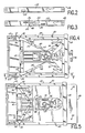
- Figure 1 is a perspective view, partly in cut-away cross-section, of one embodiment of a disk drive apparatus according to the present invention, a portion of a disk cartridge being illustrated for purposes of orientation;
- Figures 2 and 3 are end views of the disk cartridge, illustrating the engagement of a cartridge door opening mechanism of the disk drive apparatus in Figure 1;
- Figures 4, 5 and 6 are top views of the disk drive apparatus shown in Figure 1, illustrating the disk cartridge in several steps of insertion; and
- Figure 7 is a sectional view taken along the line 7-7 in Figure 4, illustrating a mechanism for raising and lowering a drive mechanism.
- Throughout the drawings like parts have been designated by the same reference numerals.
- Referring to the drawings, and in particular to Figure 1, there is illustrated a
disk drive apparatus 20 according to the present invention. Thedisk drive apparatus 20 includes aframe 22 having a ace orfront plate 24. Anopening slot receptacle 26 is provided in thefront plate 24 to receive a disk cartridge, illustrated generally at 28.Extrusions disk cartridge 28 and to guide the disk cartridge into the disk drive apparatus.Arms pins frame 22, and are biased by atension spring 42 to the poisition illustrated in Figures 1 and 4. Thespring 42 is fastened, at each end, topins arms Actuators arms disk cartridge 28, as will be hereinafter explained. - Typically, the
frame 22 will be enclosed within a cover (not shown) to protect electronic circuitry, shown generally at 21, and read/write heads shown generally at 23. Push buttons andindicators front plate 24 to provide controls for the electronic circuitry and read/write heads and to indicate their operation. Suitable feet or resilient mounting pads (not shown) may be mounted toreceptacles 29. - As shown particularly in Figure 2, the
disk cartridge 28 includes aslide door 52 which may be slid (to the left in Figure 2) to expose an opening in the top and bottom of the cartridge (not shown) to permit access to rotatable disk media (not shown) within a housing of the disk cartridge. Aslot 54 in theslide door 52 is arranged to be engaged by one or the other of theactuators slot 54 is laterally offset from the horizontal centre of the housing of the disk cartridge so that it will be above or below the horizontal centre line, depending on the orientation of the housing. A spring (not shown) biases the door towards it closed position. - With particular reference to Figures 1 to 6, as the
disk cartridge 28 is inserted in the slot receptable 26 of the disk drive apparatus and guided byextrusions actuators slot 54 of the disk cartridge. If the disk cartridge is in the orientation illustrated in Figure 2 so that theslot 54 is on the lower portion of theslide door 52, thelower actuator 48 will engage the slot. Continued insertion movement of the disk cartridge will force thearm 34 to pivot, sliding the door to the left (Figure 2) as the cartridge is moved passed the position illustrated in Figure 5 to the position illustrated in Figure 6. Theactuator 50 merely slides across the door without hampering the operation. Conversely, if the orientation of the disk cartridge is turned over, as might be desired in reading or writing on the opposite side of the disk media, theslot 54 will be orientated to the upper portion of the slide door and theupper actuator 50 engages theslot 54 to open the slide door. In either case, the disk media is exposed to the read-writeheads 23 through the opening exposed by the opened door.
Claims (5)
- A system for recording/reading data on/from a disk media and comprising a disk cartridge having a disk housing enclosing the disk media and having a door (52) on a cartridge housing moveable between one single open position wherein both surfaces of said disk are exposed for cooperation with a sensor (23) in a disk drive apparatus to enable recording and/or reading of data recorded on said disk media and a closed position wherein said disk surface is enclosed in said cartridge housing and not exposed, and bias means carried by said cartridge housing biasing said door to its closed position, wherein said cartridge housing has an access opening in each of said opposite sides permitting access to opposite sides of said disk, door opening means (34, 36, 48, 50) being provided in the disk drive apparatus for engaging said door to move it from its closed to its open position when said disk cartridge is inserted in said receiving means, said door opening means comprising an arm (34, 36) pivotably mounted to said housing (22) and an actuator (48, 50) engaging said door (52) when said disk cartridge is inserted into said receiving means, said arm and actuator opening said door as said disk cartridge is inserted into said receiving means, characterized in that- the cartridge is of the physically reversible type and- said door includes a receiver (54) laterally offset from the horizontal centre plane of said disk cartridge as to be orientated either in an upper or lower position with respect to said centre plane, dependent on the orientation of said cartridge,- said door opening means comprising first and second arms (34, 36) pivotably mounted in the housing (22), a first actuator (48) mounted to said first arm (34) to engage said receiver when said disk cartridge is in a first orientation such that said receiver is above the horizontal centre of the disk cartridge, and a second actuator (50) mounted to said second arm (36) to engage said receiver when said disk cartridge is in a second orientation opposite said first orientation such that said receiver is below the horizontal centre of the disk cartridge, whereby upon insertion of a disk cartridge into said disk drive apparatus, one or the other of said first and second actuators (48, 50) engages said receiver (54) so that continued insertion movement of the disk cartridge forces pivotal movement of the arm whose actuator engages said receiver causing the door to move from its closed to its open position against the bias of the said bias means.
- A system as claimed in claim 1, characterized in that the receiver comprises a recess in said door extending over a part of the distance of the thickness dimension of the cartridge, the actuators on the first and second arms each engaging said door over less than said distance, so that continued insertion movement of the disc cartridge forces pivotal movement of both arms, the actuator which is out of engagement with the receiver sliding over the surface of the door against the bias of said bias means.
- A disk cartridge for a system for recording/reading data on/from a disk media and having a disk housing enclosing the disk media and having a door (52) on a cartridge housing moveable between one single open position wherein both surfaces of said disk are exposed for cooperation with a sensor (23) in a disk drive apparatus to enable recording and/or reading of data recorded on said disk media and a closed position wherein said disk surface is enclosed in said cartridge housing and not exposed, and bias means carried by said cartridge housing biasing said door to its closed position, wherein said cartridge housing has an access opening in each of said opposite sides permitting access to opposite sides of said disk, wherein said cartridge is characterised by being of the physically reversible type and said door includes a receiver (54) laterally offset from the horizontal centre plane of said disk cartridge as to be orientated either in an upper or lower position with respect to said centre plane, dependent on the orientation of said cartridge.
- A disc drive apparatus for a system for recording/reading data on/from a disk media, the system comprising a disk cartridge having a disk housing enclosing the disk media and having a door (52) on a cartridge housing moveable between one single open position wherein both surfaces of said disk are exposed for cooperation with a sensor (23) in a disk drive apparatus to enable recording and/or reading of data recorded on said disk media and a closed position wherein said disk surface is enclosed in said cartridge housing and not exposed, and bias means carried by said cartridge housing biasing said door to its closed position, wherein said cartridge housing has an access opening in each of said opposite sides permitting access to opposite sides of said disk, door opening means (34, 36, 48, 50) being provided in the disk drive apparatus for engaging said door to move it from its closed to its open position when said disk cartridge is inserted in said receiving means, said door opening means comprising an arm (34, 36) pivotably mounted to said housing (22) and an actuator (48, 50) engaging said door (52) when said disk cartridge is inserted into said receiving means, said arm and actuator opening said door as said disk cartridge is inserted into said receiving means, wherein the cartridge is of the physically reversible type and said door includes a receiver (54) laterally offset from the horizontal centre plane of said disk cartridge as to be orientated either in a upper or lower position with respect to said centre plane, dependent on the orientation of said cartridge, said door opening means being characterised by comprising first and second arms (34, 36) pivotably mounted in the housing (22), a first actuator (48) mounted to said first arm (34) to engage said receiver when said disk cartridge is in a first orientation such that said receiver is above the horizontal centre of the disk cartridge, and a second actuator (50) mounted to said second arm (36) to engage said receiver when said disk cartridge is in a second orientation opposite said first orientation such that said receiver is below the horizontal centre of the disk cartridge, whereby upon insertion of a disk cartridge into said disk drive apparatus, one or the other of said first and second actuators (48, 50) engages said receiver (54) so that continued insertion movement of the disk cartridge forces pivotal movement of the arm whose actuator engages said receiver causing the door to move from its closed to its open position against the bias of the said bias means.
- A disk drive apparatus according to claim 4, said arms being movable in two different, parallel planes.
Priority Applications (1)
| Application Number | Priority Date | Filing Date | Title |
|---|---|---|---|
| AT86304345T ATE94304T1 (en) | 1985-09-19 | 1986-06-06 | DISK DRIVE DEVICE. |
Applications Claiming Priority (2)
| Application Number | Priority Date | Filing Date | Title |
|---|---|---|---|
| US06/777,814 US4745500A (en) | 1985-09-19 | 1985-09-19 | Disk drive for cartridge disks |
| US777814 | 1985-09-19 |
Publications (3)
| Publication Number | Publication Date |
|---|---|
| EP0216442A2 EP0216442A2 (en) | 1987-04-01 |
| EP0216442A3 EP0216442A3 (en) | 1989-05-03 |
| EP0216442B1 true EP0216442B1 (en) | 1993-09-08 |
Family
ID=25111363
Family Applications (1)
| Application Number | Title | Priority Date | Filing Date |
|---|---|---|---|
| EP86304345A Expired - Lifetime EP0216442B1 (en) | 1985-09-19 | 1986-06-06 | Disk drive apparatus |
Country Status (10)
| Country | Link |
|---|---|
| US (1) | US4745500A (en) |
| EP (1) | EP0216442B1 (en) |
| JP (1) | JPS6267769A (en) |
| KR (1) | KR870003490A (en) |
| CN (1) | CN86106358A (en) |
| AT (1) | ATE94304T1 (en) |
| AU (1) | AU603335B2 (en) |
| CA (2) | CA1304819C (en) |
| DE (1) | DE3688995T2 (en) |
| HK (1) | HK20595A (en) |
Families Citing this family (24)
| Publication number | Priority date | Publication date | Assignee | Title |
|---|---|---|---|---|
| JPS62273652A (en) * | 1986-05-21 | 1987-11-27 | Copal Co Ltd | Shutter switching mechanism for disk cartridge |
| US4964005A (en) * | 1987-01-19 | 1990-10-16 | Canon Kabushiki Kaisha | Information recording/reproducing apparatus having swingate levers for opening and closing shutter of cartridge in response to insertion and ejection of cartridge |
| US5014258A (en) * | 1988-10-03 | 1991-05-07 | Pioneer Electronic Corp. | Disc player having means for preventing disc magazine from being inserted upsidedown |
| US5053903A (en) * | 1989-03-28 | 1991-10-01 | Literal Corporation | Disk clamp positioning apparatus for information storage disk drive system |
| JP2718182B2 (en) * | 1989-06-01 | 1998-02-25 | ソニー株式会社 | Disc player |
| DE69033899T2 (en) * | 1989-07-05 | 2002-06-27 | Hitachi Maxell, Ltd. | disk cartridge |
| US4932522A (en) * | 1989-09-21 | 1990-06-12 | Milovich Steven L | CD storage with automatic opening device |
| JPH0371480U (en) * | 1989-11-13 | 1991-07-19 | ||
| JPH0520759A (en) * | 1991-04-19 | 1993-01-29 | Sony Corp | Disk drive device |
| US6430005B1 (en) | 1991-10-18 | 2002-08-06 | Syquest Technology, Inc. | Removable cartridge disk drive with a receiver for receiving a cartridge housing a hard disk |
| DE69328673T2 (en) * | 1992-03-10 | 2001-02-01 | Iomega Corp., Roy | DISK DRIVE WITH INTERCHANGEABLE CASSETTE TO RECEIVE A CASSETTE THAT CONTAINS A 3.5 INCH DISK WITH 105MB |
| JP3070791B2 (en) * | 1992-03-19 | 2000-07-31 | ソニー株式会社 | Disk loading device and disk device |
| US5608705A (en) * | 1992-03-19 | 1997-03-04 | Sony Corporation | Disk loading apparatus with rotationally engaging disk table |
| US5724331A (en) * | 1994-08-25 | 1998-03-03 | Discovision Associates | Disk drive system having improved cartridge-loading apparatus including direct drive gear train and methods for making and operating same |
| US6009061A (en) * | 1994-08-25 | 1999-12-28 | Discovision Associates | Cartridge-loading apparatus with improved base plate and cartridge receiver latch |
| US5583710A (en) * | 1995-05-10 | 1996-12-10 | Iomega Corporation | Disk drive having an automatic spindle motor loading mechanism |
| US5912786A (en) * | 1996-06-03 | 1999-06-15 | Iomega Corporation | Disk drive apparatus having an improved spindle motor loading mechanism |
| JPH10208412A (en) * | 1997-01-23 | 1998-08-07 | Alps Electric Co Ltd | Disk apparatus |
| US6072666A (en) | 1997-05-30 | 2000-06-06 | Iomega Corporation | Head retraction system for retracting the heads of a disk drive |
| US6301082B1 (en) | 1997-05-30 | 2001-10-09 | Iomega Corporation | Operating system for operating an eject system and a head retraction system of a disk drive |
| US6002547A (en) * | 1997-05-30 | 1999-12-14 | Iomega Corporation | Disk drive with a rotatably mounted disk drive motor |
| US6064548A (en) * | 1997-05-30 | 2000-05-16 | Iomega Corporation | Eject system for ejecting a disk cartridge from a disk drive |
| US6128151A (en) * | 1997-10-29 | 2000-10-03 | Iomega Corporation | Method and a system for engaging a disk drive spindle motor with a disk cartridge |
| US5974026A (en) | 1997-11-14 | 1999-10-26 | Castlewood Systems, Inc. | Anti-rattle mechanism for a removable video disk cartridge |
Family Cites Families (20)
| Publication number | Priority date | Publication date | Assignee | Title |
|---|---|---|---|---|
| GB1542882A (en) * | 1975-03-20 | 1979-03-28 | Matsushita Electric Industrial Co Ltd | Tape cassette machines |
| US4523240A (en) * | 1977-12-22 | 1985-06-11 | Micropolis | High precision floppy disc memory system |
| GB1570857A (en) * | 1977-12-23 | 1980-07-09 | Ibm | Disc cartridge record/playback apparatus |
| DE3019928C2 (en) * | 1980-05-24 | 1984-08-30 | Philips Patentverwaltung Gmbh, 2000 Hamburg | Player for discs provided with information |
| JPS593399Y2 (en) * | 1980-07-11 | 1984-01-30 | 株式会社東芝 | Turntable lifting device |
| JPS606938Y2 (en) * | 1980-08-14 | 1985-03-07 | ソニー株式会社 | Disc cassette for recording and playback |
| JPS5736473A (en) * | 1980-08-14 | 1982-02-27 | Sony Corp | Rotating driving device |
| JPS6138145Y2 (en) * | 1980-08-14 | 1986-11-04 | ||
| US4399480A (en) * | 1981-03-30 | 1983-08-16 | Disctron, Inc. | Head access door, opening mechanism and method of sealing |
| US4525758A (en) * | 1981-06-19 | 1985-06-25 | Matsushita Electric Industrial Co., Ltd. | Cartridge |
| JPS5897166A (en) * | 1981-12-03 | 1983-06-09 | Sony Corp | Floppy disc cassette |
| JPS58127565A (en) * | 1982-01-21 | 1983-07-29 | Matsushita Electric Ind Co Ltd | Constant-voltage power source |
| AU564288B2 (en) * | 1982-01-27 | 1987-08-06 | Sony Corporation | Micro-floppy disc cassette |
| BE893023A (en) * | 1982-04-29 | 1982-08-16 | Staar Sa | RECORDER WITH AUTOMATIC DISC LOADING. |
| JPS59177073U (en) * | 1983-05-13 | 1984-11-27 | ソニー株式会社 | disc cassette |
| GB2142464B (en) * | 1983-06-15 | 1986-10-15 | Alps Electric Co Ltd | Recording and reproducing apparatus for disc cartridges |
| BE897325A (en) * | 1983-07-19 | 1983-11-14 | Staar Sa | DISPOSITIF DE POSITIONNEMENT POUR DISQUES DANS UN APPAREIL D'ENREGISTREMENT ET / OU DE REPRODUCTION. |
| JPS6051650U (en) * | 1983-09-12 | 1985-04-11 | キヤノン株式会社 | magnetic disk device |
| JPS6089654U (en) * | 1983-11-24 | 1985-06-19 | パイオニア株式会社 | front loading disk player |
| JPS60117464A (en) * | 1983-11-30 | 1985-06-24 | Teac Co | Magnetic disc driving device |
-
1985
- 1985-09-19 US US06/777,814 patent/US4745500A/en not_active Expired - Lifetime
-
1986
- 1986-03-24 CA CA000504865A patent/CA1304819C/en not_active Expired - Lifetime
- 1986-04-07 JP JP61078435A patent/JPS6267769A/en active Pending
- 1986-06-06 EP EP86304345A patent/EP0216442B1/en not_active Expired - Lifetime
- 1986-06-06 DE DE86304345T patent/DE3688995T2/en not_active Expired - Lifetime
- 1986-06-06 AT AT86304345T patent/ATE94304T1/en not_active IP Right Cessation
- 1986-06-18 AU AU58812/86A patent/AU603335B2/en not_active Ceased
- 1986-09-12 KR KR1019860007691A patent/KR870003490A/en not_active Withdrawn
- 1986-09-19 CN CN198686106358A patent/CN86106358A/en active Pending
-
1992
- 1992-02-05 CA CA000616308A patent/CA1319981C/en not_active Expired - Lifetime
-
1995
- 1995-02-16 HK HK20595A patent/HK20595A/en not_active IP Right Cessation
Also Published As
| Publication number | Publication date |
|---|---|
| AU5881286A (en) | 1987-03-26 |
| HK20595A (en) | 1995-02-24 |
| EP0216442A2 (en) | 1987-04-01 |
| AU603335B2 (en) | 1990-11-15 |
| US4745500A (en) | 1988-05-17 |
| JPS6267769A (en) | 1987-03-27 |
| CA1304819C (en) | 1992-07-07 |
| EP0216442A3 (en) | 1989-05-03 |
| DE3688995T2 (en) | 1994-03-17 |
| DE3688995D1 (en) | 1993-10-14 |
| CA1319981C (en) | 1993-07-06 |
| KR870003490A (en) | 1987-04-17 |
| CN86106358A (en) | 1987-04-01 |
| ATE94304T1 (en) | 1993-09-15 |
Similar Documents
| Publication | Publication Date | Title |
|---|---|---|
| HK20595A (en) | Disk drive apparatus | |
| US4823214A (en) | Disk drive for cartridge disks | |
| US5216558A (en) | Drawer loading removable cartridge disk drive | |
| CA1188795A (en) | Magnetic disk cartridge | |
| KR960001674Y1 (en) | Disc cassette | |
| US4791511A (en) | Disk cartridge with slide door engageable in either of two orientations | |
| EP0219415A2 (en) | Recording and/or reproducing apparatus for flexible magnetic disks | |
| EP0402037B1 (en) | Disk Cartridge | |
| US4146912A (en) | Disk interlock mechanism | |
| US6760914B2 (en) | Disk reproducing apparatus | |
| US6473261B1 (en) | Cartridge overinsertion protection for cartridge library | |
| EP0982729B1 (en) | Disc cartridge | |
| US4747001A (en) | Disk cartridge and device for driving the same | |
| US5222005A (en) | Loading unit for case which houses recording disk | |
| US5535076A (en) | Head driving device having a plurality of pins arranged for engagement with lead screw | |
| US6466396B1 (en) | Cartridge library | |
| US6462900B1 (en) | Cartridge picker robot with ribbon cable for cartridge library | |
| US4603362A (en) | Guiding and registering different thickness diskettes in a disk drive | |
| US5495374A (en) | Automatic loader mechanism for magnetic tape cartridge with tension control | |
| US4647995A (en) | Magnetic recording and/or reproducing apparatus | |
| US20010033443A1 (en) | Large capacity disk drive | |
| CA2262703C (en) | Magnetic disk cartridge | |
| JP3536721B2 (en) | Cartridge transfer device | |
| JP2506172Y2 (en) | Cassette tape recorder | |
| JP3551500B2 (en) | Disk unit |
Legal Events
| Date | Code | Title | Description |
|---|---|---|---|
| PUAI | Public reference made under article 153(3) epc to a published international application that has entered the european phase |
Free format text: ORIGINAL CODE: 0009012 |
|
| AK | Designated contracting states |
Kind code of ref document: A2 Designated state(s): AT BE CH DE FR GB IT LI LU NL SE |
|
| PUAL | Search report despatched |
Free format text: ORIGINAL CODE: 0009013 |
|
| AK | Designated contracting states |
Kind code of ref document: A3 Designated state(s): AT BE CH DE FR GB IT LI LU NL SE |
|
| 17P | Request for examination filed |
Effective date: 19891101 |
|
| 17Q | First examination report despatched |
Effective date: 19910304 |
|
| RAP1 | Party data changed (applicant data changed or rights of an application transferred) |
Owner name: N.V. PHILIPS' GLOEILAMPENFABRIEKEN |
|
| GRAA | (expected) grant |
Free format text: ORIGINAL CODE: 0009210 |
|
| AK | Designated contracting states |
Kind code of ref document: B1 Designated state(s): AT BE CH DE FR GB IT LI LU NL SE |
|
| PG25 | Lapsed in a contracting state [announced via postgrant information from national office to epo] |
Ref country code: SE Effective date: 19930908 Ref country code: NL Effective date: 19930908 Ref country code: LI Effective date: 19930908 Ref country code: CH Effective date: 19930908 Ref country code: BE Effective date: 19930908 Ref country code: AT Effective date: 19930908 |
|
| REF | Corresponds to: |
Ref document number: 94304 Country of ref document: AT Date of ref document: 19930915 Kind code of ref document: T |
|
| REF | Corresponds to: |
Ref document number: 3688995 Country of ref document: DE Date of ref document: 19931014 |
|
| ITF | It: translation for a ep patent filed | ||
| ET | Fr: translation filed | ||
| REG | Reference to a national code |
Ref country code: CH Ref legal event code: PL |
|
| NLV1 | Nl: lapsed or annulled due to failure to fulfill the requirements of art. 29p and 29m of the patents act | ||
| ITTA | It: last paid annual fee | ||
| PG25 | Lapsed in a contracting state [announced via postgrant information from national office to epo] |
Ref country code: LU Free format text: LAPSE BECAUSE OF NON-PAYMENT OF DUE FEES Effective date: 19940630 |
|
| PLBE | No opposition filed within time limit |
Free format text: ORIGINAL CODE: 0009261 |
|
| STAA | Information on the status of an ep patent application or granted ep patent |
Free format text: STATUS: NO OPPOSITION FILED WITHIN TIME LIMIT |
|
| 26N | No opposition filed | ||
| ITPR | It: changes in ownership of a european patent |
Owner name: CAMBIO RAGIONE SOCIALE;PHILIPS ELECTRONICS N.V. |
|
| REG | Reference to a national code |
Ref country code: FR Ref legal event code: CD |
|
| REG | Reference to a national code |
Ref country code: FR Ref legal event code: CD |
|
| REG | Reference to a national code |
Ref country code: GB Ref legal event code: IF02 |
|
| PGFP | Annual fee paid to national office [announced via postgrant information from national office to epo] |
Ref country code: IT Payment date: 20050627 Year of fee payment: 20 |
|
| PGFP | Annual fee paid to national office [announced via postgrant information from national office to epo] |
Ref country code: GB Payment date: 20050628 Year of fee payment: 20 Ref country code: FR Payment date: 20050628 Year of fee payment: 20 |
|
| REG | Reference to a national code |
Ref country code: GB Ref legal event code: PE20 |
|
| PGFP | Annual fee paid to national office [announced via postgrant information from national office to epo] |
Ref country code: DE Payment date: 20050816 Year of fee payment: 20 |
|
| PG25 | Lapsed in a contracting state [announced via postgrant information from national office to epo] |
Ref country code: GB Free format text: LAPSE BECAUSE OF EXPIRATION OF PROTECTION Effective date: 20060605 |