EP0215660B1 - Interferometric apparatus - Google Patents
Interferometric apparatus Download PDFInfo
- Publication number
- EP0215660B1 EP0215660B1 EP86307085A EP86307085A EP0215660B1 EP 0215660 B1 EP0215660 B1 EP 0215660B1 EP 86307085 A EP86307085 A EP 86307085A EP 86307085 A EP86307085 A EP 86307085A EP 0215660 B1 EP0215660 B1 EP 0215660B1
- Authority
- EP
- European Patent Office
- Prior art keywords
- radiation
- movement
- vibrating
- interferometric measurement
- vibration
- Prior art date
- Legal status (The legal status is an assumption and is not a legal conclusion. Google has not performed a legal analysis and makes no representation as to the accuracy of the status listed.)
- Expired
Links
- 238000005259 measurement Methods 0.000 claims description 16
- 230000005855 radiation Effects 0.000 claims description 15
- 238000005286 illumination Methods 0.000 claims description 13
- 230000001427 coherent effect Effects 0.000 claims description 2
- 230000001419 dependent effect Effects 0.000 claims description 2
- 230000015572 biosynthetic process Effects 0.000 claims 1
- 238000001093 holography Methods 0.000 description 8
- 238000004458 analytical method Methods 0.000 description 7
- 230000003287 optical effect Effects 0.000 description 7
- 230000000694 effects Effects 0.000 description 5
- 238000000034 method Methods 0.000 description 5
- 238000006073 displacement reaction Methods 0.000 description 3
- 238000012545 processing Methods 0.000 description 3
- 230000033458 reproduction Effects 0.000 description 3
- XKRFYHLGVUSROY-UHFFFAOYSA-N Argon Chemical compound [Ar] XKRFYHLGVUSROY-UHFFFAOYSA-N 0.000 description 2
- 230000001133 acceleration Effects 0.000 description 2
- 238000007796 conventional method Methods 0.000 description 2
- 230000007423 decrease Effects 0.000 description 2
- 238000011161 development Methods 0.000 description 2
- 230000018109 developmental process Effects 0.000 description 2
- 239000000839 emulsion Substances 0.000 description 2
- 238000005516 engineering process Methods 0.000 description 2
- 229920001169 thermoplastic Polymers 0.000 description 2
- 239000004416 thermosoftening plastic Substances 0.000 description 2
- 229910052786 argon Inorganic materials 0.000 description 1
- 239000013078 crystal Substances 0.000 description 1
- 125000004122 cyclic group Chemical group 0.000 description 1
- 238000013461 design Methods 0.000 description 1
- 230000005284 excitation Effects 0.000 description 1
- 230000001747 exhibiting effect Effects 0.000 description 1
- 239000000835 fiber Substances 0.000 description 1
- 238000011065 in-situ storage Methods 0.000 description 1
- 238000005305 interferometry Methods 0.000 description 1
- 238000004519 manufacturing process Methods 0.000 description 1
- 239000000463 material Substances 0.000 description 1
- 238000012986 modification Methods 0.000 description 1
- 230000004048 modification Effects 0.000 description 1
- 239000004065 semiconductor Substances 0.000 description 1
- 230000035945 sensitivity Effects 0.000 description 1
- 238000000926 separation method Methods 0.000 description 1
- 239000007787 solid Substances 0.000 description 1
- 230000003068 static effect Effects 0.000 description 1
- 238000012360 testing method Methods 0.000 description 1
- XLYOFNOQVPJJNP-UHFFFAOYSA-N water Substances O XLYOFNOQVPJJNP-UHFFFAOYSA-N 0.000 description 1
Images

Classifications
-
- G—PHYSICS
- G01—MEASURING; TESTING
- G01H—MEASUREMENT OF MECHANICAL VIBRATIONS OR ULTRASONIC, SONIC OR INFRASONIC WAVES
- G01H9/00—Measuring mechanical vibrations or ultrasonic, sonic or infrasonic waves by using radiation-sensitive means, e.g. optical means
- G01H9/002—Measuring mechanical vibrations or ultrasonic, sonic or infrasonic waves by using radiation-sensitive means, e.g. optical means for representing acoustic field distribution
Definitions
- This invention relates to apparatus for interferometric measurement and, in particular, to the modal analysis of vibrating structures by means of electronic speckle pattern interferometry (ESPI).
- ESPI electronic speckle pattern interferometry
- the conventional method of assessing the modal behaviour of structures is by the use of accelerometers.
- the object of performing such modal analysis is to gain an understanding of how the structure vibrates so that improvements in its behaviour can be introduced.
- For an engine assembly this may involve modifications to the design, constraints on the way the engine is installed in the vehicle and an indication of the engine's likely noise radiating properties.
- Accelerometers monitor the surface vibration of the structure while it is being excited either sinusoidally or more generally by random or pseudo-random input.
- the input is usually provided by an electro-mechanical vibrator attached to the structure.
- a series of acceleration measurements are taken over the structure, recorded and analysed by computer to furnish a display _ usually animated _ of how the structure vibrates at its resonant frequencies. As the frequency of the vibration modes increases the spatial size of the modes decreases and the separation of accelerometers used to make the measurements must be reduced accordingly.
- the procedure would involve making measurements at typically 100 positions on the side of the block using a 5 cm grid. This would enable modes up to typically 4000 Hz to be analysed.
- the noise characteristics of engines are such that modal information above this frequency is usually not required. It would not be feasible to carry out measurements at higher frequencies because the task of acquiring acceleration data at many more than 100 sites on each side of an engine would be prohibitively time consuming.
- the information about the vibration behaviour stored in the hologram can be displayed in the form of a set of fringes each of which defines a line of equal vibration amplitude. Areas on the structure which have not vibrated (nodes) appear as bright fringes on the image of the structure reconstructed by the hologram. Areas which have executed vibration displacements with an amplitude of ⁇ /4 ( ⁇ is the wavelength of laser illumination used to make the hologram) also appear as bright fringes. These, however, are not as bright as the nodes. Larger amplitude vibrations appear as fringes with a contour interval of ⁇ /4 and with progressively less distinct fringes being generated as the vibration amplitude increases.
- Such holographic vibration maps can provide very useful information about vibration characteristics of structures.
- drawbacks to the acquisition of such modal maps The measurements are accomplished by using the interference properties of laser illumination and, hence, they must be carried out under conditions of extreme stability if the necessity for a pulsed laser is to be avoided. Although severe these interferometric requirements can be satisfied in a laboratory environment.
- a more serious limitation to the practical application of such optical modal analysis techniques based on holography is that a photographic processing stage is involved.
- thermo-plastic/electrostatic principles cannot perform the real-time vibration scanning role that is required.
- the sensitivity of these mediums is less than typical holographic plates and as their spatial resolution is also lower the size of the object which can be investigated is in practice severely limited.
- any holographic based system must operate in the live fringe mode. This puts constraints on the stability requirements for the system and the hologram material that are not currently satisfied by thermoplastic media.
- apparatus for the interferometric measurement of the movement of a vibrating object comprising a source of coherent radiation arranged to illuminate the object, means for focusing radiation scattered from a surface of the object on to a television camera radiation sensor to produce an electrical signal dependent on the instantaneous amplitude of the received scattered radiation, further means for focusing radiation from a reference beam on to said radiation sensor to generate a speckle pattern characteristic of the object at a given position and comparator means including a frame store to compare the speckle patterns characteristic of the object at a first and a second position and further incorporating means for varying the direction of illumination of said object by radiation from said source.
- the technique of ESPI replaces the photographic stage of holography with an electronic processing stage and utilises a high resolution TV camera instead of a photographic emulsion.
- the result is a system which can measure in real-time the vibration modes of a structure and display them on a TV.
- the system is based, like holography, on the phenomenon of optical interference. It uses illumination and requires that the whole measurement system be isolated from extraneous vibrations. This is usually accomplished by the use of an air cushion optical table, in a manner identical to that used with a holographic system.
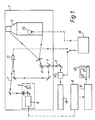
- Figure 1 is a schematic drawing of a typical ESPI system which consists, in essence, of three parts, a test bed 1 on which the components under study are mounted, the optics for illuminating and viewing the component and the electronics for processing the video image.
- the system is similar to that of focused image holography.
- An object 2 is uniformly illuminated by a laser beam 3 produced by an argon laser 16 and light scattered from the surface of the object is imaged onto a high resolution TV camera sensor 4 by a lens 5.
- a beamsplitting device 6 is positioned such that a second uniform wavefront from the laser can be introduced onto the camera sensor, in addition to the first.
- This second beam 7 is obtained by a beam splitter 6 which separates a fraction of the light out of the laser beam before it illuminates the object.
- the secondary beam 7 acts as a reference wavefront in the system.
- speckles contain information about the positions in space of the illuminated points relative to the observer. If the wavefront from the object carrying this information is mixed with a reference wavefront ⁇ as in the ESPI system _ then a particularly simple relationship between speckle behaviour and object movement results.
- the information about the object is stored as a very high frequency spatial carrier wave in the photographic emulsion (typically 1/2000 mm in spacing) and is thus not capable of being recorded directly with a TV camera which operates with typically 625 lines.
- a speckle pattern of the object can be held in a frame store 8, 9 to act as a reference object position. Subsequent movement of the object, recorded at TV frame rate, will result in changes in the speckle pattern intensity. Simply by continuously subtracting new TV images from the stored record a display of contour lines of object displacement can be generated. This appears on the TV monitor 10 in the system as a set of dark fringes _ the loci of equal object movements.
- Figure 2 is a photographic reproduction of a conventional ESPI time average modal map which suffers from the disadvantages that detailed structure of the object cannot be seen, no more than two or three fringes can be counted and no phase information is present.
- the information in a speckle pattern interferogram is carried by the randomly sized and positioned speckles. This is true for both the fringe information and the object detail. If a time-average fringe map of a vibration mode is generated it is found that the positions of the fringes does not change much for a small change of a few degrees in the angle at which the laser illuminates the object. However, the brightness of individual speckles in the pattern varies over this small change in the object illumination angle. Hence, if several interferograms, each with a different object illumination direction, are added together and the result displayed, the stationary fringes reinforce in each record but the background speckles average to some uniform level. As the object detail is also stationary with respect to object illumination beam direction it too is enhanced in the resulting speckle.
- a scatter plate 11 Positioned in front of the object is a scatter plate 11. Records, averaged over a period of several seconds, form fringe maps of holographic quality, exhibiting an improvement in clarity from that depicted in Figure 2 to that shown in Figure 3.
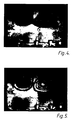
- Speckle pattern vibration maps suffer from a problem in common with holographic time-average vibration maps. As the amplitude of the vibration increases the visibility of the fringes decreases. An example of this is shown in Figure 4 which is a speckle average vibration map of the side of an engine being excited at 3.25 KHz. A zoom lens has been used to give a close up of this region of the water jacket mode. The cause of this loss of fringe visibility is the time average mode of operation used in which speckle patterns are added during the whole of the vibration cycle.
- Figure 5 is a speckle strobed version of Figure 4 _ the structure being excited at 3.25 KHz; the Pockel's Cell running at 6.50 KHz.
- Figure 5 shows the improvement in fringe visibility at high amplitude vibration sites as a result of using strobed illumination.
- a vibration analysis system needs to be capable of operating in a time-average mode and in a strobed mode.
- the reason for this is that in the time-average mode the variation in fringe visibility is in itself useful as it identifies regions of the object which are not vibrating at all _ these will be the brightest parts of the vibration map and are frequently of particular interest.
- the problem of assigning phase to the modal maps produced by either holography or ESPI can be solved by introducing phase modulation into the reference beam path in the system.
- the map of Figure 5 demonstrates the ambiguity inherent in the fringes.
- the two adjacent sets of fringes show the amplitude of the vibrations of the block walls.
- Information about the phase behaviour of the structure can be obtained optically over the whole of the surface by reflecting the reference beam from a mirror 13 mounted on a piezo-electric crystal and driving the mirror from an oscillator 14 at the same frequency as the vibrator 15.
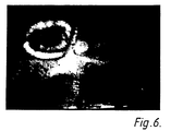
- FIG. 6 An example of this effect is shown in Figure 6 in which the speckle average map of Figure 5 is repeated with the reference beam vibrated 180° out-of-phase with the vibrator.
- the first bright contour on the left-hand set of fringes is highlighted. This shows that this region of the object is moving 180° out-of-phase with the vibrator.
- the two high amplitude vibration regions identified in Figure 5 are thus moving in anti-phase.
Landscapes
- Engineering & Computer Science (AREA)
- Radar, Positioning & Navigation (AREA)
- Remote Sensing (AREA)
- Physics & Mathematics (AREA)
- General Physics & Mathematics (AREA)
- Measurement Of Mechanical Vibrations Or Ultrasonic Waves (AREA)
- Holo Graphy (AREA)
Description
- This invention relates to apparatus for interferometric measurement and, in particular, to the modal analysis of vibrating structures by means of electronic speckle pattern interferometry (ESPI).
- The conventional method of assessing the modal behaviour of structures is by the use of accelerometers. The object of performing such modal analysis is to gain an understanding of how the structure vibrates so that improvements in its behaviour can be introduced. For an engine assembly this may involve modifications to the design, constraints on the way the engine is installed in the vehicle and an indication of the engine's likely noise radiating properties.
- Accelerometers monitor the surface vibration of the structure while it is being excited either sinusoidally or more generally by random or pseudo-random input. The input is usually provided by an electro-mechanical vibrator attached to the structure. A series of acceleration measurements are taken over the structure, recorded and analysed by computer to furnish a display _ usually animated _ of how the structure vibrates at its resonant frequencies. As the frequency of the vibration modes increases the spatial size of the modes decreases and the separation of accelerometers used to make the measurements must be reduced accordingly.
- For an engine assembly the procedure would involve making measurements at typically 100 positions on the side of the block using a 5 cm grid. This would enable modes up to typically 4000 Hz to be analysed. The noise characteristics of engines are such that modal information above this frequency is usually not required. It would not be feasible to carry out measurements at higher frequencies because the task of acquiring acceleration data at many more than 100 sites on each side of an engine would be prohibitively time consuming.
- In view of the time needed to perform such modal analysis the use of optical techniques for the measurement of vibration behaviour of structures has been investigated. Potentially, optical methods have the capability to make rapid, full-field, non-contacting measurements of vibration behaviour. In the past holography has been used to record vibration contour maps of many engineering components _ particularly by the aerospace industry. (Butters, J.N. "Applications of ESPI to NDT", Optics and Laser Technology, VOL 9 (1977) 117-123.) It is known from U.S. Patent 3816649 and from Optics and Laser Technology 14 No.1 (Feb 1982) pp21-25 to use a comparator to compare the speckle patterns characteristic of an object at two positions. The information about the vibration behaviour stored in the hologram can be displayed in the form of a set of fringes each of which defines a line of equal vibration amplitude. Areas on the structure which have not vibrated (nodes) appear as bright fringes on the image of the structure reconstructed by the hologram. Areas which have executed vibration displacements with an amplitude of λ/4 (λ is the wavelength of laser illumination used to make the hologram) also appear as bright fringes. These, however, are not as bright as the nodes. Larger amplitude vibrations appear as fringes with a contour interval of λ/4 and with progressively less distinct fringes being generated as the vibration amplitude increases.
- Such holographic vibration maps can provide very useful information about vibration characteristics of structures. There are, however, drawbacks to the acquisition of such modal maps. The measurements are accomplished by using the interference properties of laser illumination and, hence, they must be carried out under conditions of extreme stability if the necessity for a pulsed laser is to be avoided. Although severe these interferometric requirements can be satisfied in a laboratory environment. A more serious limitation to the practical application of such optical modal analysis techniques based on holography is that a photographic processing stage is involved.
- This means that the production of a modal map by time-average holography takes typically 20 minutes. Furthermore it is necessary to know the resonances of interest before a hologram is produced.
- Rapid in situ holographic development systems are available relying on thermo-plastic/electrostatic principles but these cannot perform the real-time vibration scanning role that is required. The sensitivity of these mediums is less than typical holographic plates and as their spatial resolution is also lower the size of the object which can be investigated is in practice severely limited. Further, if as is desirable, the structure is to be studied as the excitation frequency is scanned, any holographic based system must operate in the live fringe mode. This puts constraints on the stability requirements for the system and the hologram material that are not currently satisfied by thermoplastic media.
- According to the present invention, there is provided apparatus for the interferometric measurement of the movement of a vibrating object comprising a source of coherent radiation arranged to illuminate the object, means for focusing radiation scattered from a surface of the object on to a television camera radiation sensor to produce an electrical signal dependent on the instantaneous amplitude of the received scattered radiation, further means for focusing radiation from a reference beam on to said radiation sensor to generate a speckle pattern characteristic of the object at a given position and comparator means including a frame store to compare the speckle patterns characteristic of the object at a first and a second position and further incorporating means for varying the direction of illumination of said object by radiation from said source.
- The technique of ESPI replaces the photographic stage of holography with an electronic processing stage and utilises a high resolution TV camera instead of a photographic emulsion. The result is a system which can measure in real-time the vibration modes of a structure and display them on a TV. The system is based, like holography, on the phenomenon of optical interference. It uses illumination and requires that the whole measurement system be isolated from extraneous vibrations. This is usually accomplished by the use of an air cushion optical table, in a manner identical to that used with a holographic system.
- An embodiment of the invention will now be described by way of example with reference to the accompanying drawings in which:
- Figure 1 is a diagrammatic representation of an electronic speckle interferometer system
- Figure 2 is a photographic reproduction of an ESPI time average modal map produced by conventional methods; and
- Figures 3-6 are photographic reproductions of speckle averaged modal maps.
- Referring now to the drawings, Figure 1 is a schematic drawing of a typical ESPI system which consists, in essence, of three parts, a
test bed 1 on which the components under study are mounted, the optics for illuminating and viewing the component and the electronics for processing the video image. - In operation the system is similar to that of focused image holography. An object 2 is uniformly illuminated by a laser beam 3 produced by an
argon laser 16 and light scattered from the surface of the object is imaged onto a high resolutionTV camera sensor 4 by alens 5. Between the lens and the sensor a beamsplitting device 6 is positioned such that a second uniform wavefront from the laser can be introduced onto the camera sensor, in addition to the first. Thissecond beam 7 is obtained by a beam splitter 6 which separates a fraction of the light out of the laser beam before it illuminates the object. Thesecondary beam 7 acts as a reference wavefront in the system. The appearance of an object in laser illumination is quite different from that in incandescent illumination in that the surface of the object appears to be ′grainy′ or ′speckled′. These speckles contain information about the positions in space of the illuminated points relative to the observer. If the wavefront from the object carrying this information is mixed with a reference wavefront λ as in the ESPI system _ then a particularly simple relationship between speckle behaviour and object movement results. - For the system shown in Figure 1, movements of the object along the optical axis of the camera will result in cyclical variations in the brightness of speckles. The speckles will cycle in brightness every time the object moves line-of-sight by λ/2, where λ is the wavelength of laser illumination used. As the speckles can be made to be large enough to be resolved by the camera sensor simply by closing the lens aperture sufficiently, it is possible to monitor these cyclic variations in speckle brightness with a IV camera.
- In a holographic system, the information about the object is stored as a very high frequency spatial carrier wave in the photographic emulsion (typically 1/2000 mm in spacing) and is thus not capable of being recorded directly with a TV camera which operates with typically 625 lines.
- In the ESPI system a speckle pattern of the object can be held in a
frame store 8, 9 to act as a reference object position. Subsequent movement of the object, recorded at TV frame rate, will result in changes in the speckle pattern intensity. Simply by continuously subtracting new TV images from the stored record a display of contour lines of object displacement can be generated. This appears on theTV monitor 10 in the system as a set of dark fringes _ the loci of equal object movements. - If the object is vibrating, rather than suffering a static displacement, then analysis shows that, like time-average holography, fringes of equal vibration amplitude will be generated.
- Figure 2 is a photographic reproduction of a conventional ESPI time average modal map which suffers from the disadvantages that detailed structure of the object cannot be seen, no more than two or three fringes can be counted and no phase information is present.
- Various features incorporated in the apparatus of Figure 1 may be used to overcome these disadvantages.
- The information in a speckle pattern interferogram is carried by the randomly sized and positioned speckles. This is true for both the fringe information and the object detail. If a time-average fringe map of a vibration mode is generated it is found that the positions of the fringes does not change much for a small change of a few degrees in the angle at which the laser illuminates the object. However, the brightness of individual speckles in the pattern varies over this small change in the object illumination angle. Hence, if several interferograms, each with a different object illumination direction, are added together and the result displayed, the stationary fringes reinforce in each record but the background speckles average to some uniform level. As the object detail is also stationary with respect to object illumination beam direction it too is enhanced in the resulting speckle.
- Positioned in front of the object is a
scatter plate 11. Records, averaged over a period of several seconds, form fringe maps of holographic quality, exhibiting an improvement in clarity from that depicted in Figure 2 to that shown in Figure 3. - Speckle pattern vibration maps suffer from a problem in common with holographic time-average vibration maps. As the amplitude of the vibration increases the visibility of the fringes decreases. An example of this is shown in Figure 4 which is a speckle average vibration map of the side of an engine being excited at 3.25 KHz. A zoom lens has been used to give a close up of this region of the water jacket mode. The cause of this loss of fringe visibility is the time average mode of operation used in which speckle patterns are added during the whole of the vibration cycle.
- If the object is illuminated only at the extremes of its vibration cycle then this reduction in fringe visibility with increasing vibration amplitude is avoided and all fringes are equally bright. A Pockel's
Cell 12 in the laser beam acting as a very fast shutter achieves this. By driving the Pockel's Cell from the same signal generator as the vibrator, but at twice the frequency, a strobing effect is produced which increases the visibility of high vibration amplitude fringes. - An example of its effect is shown in Figure 5 which is a speckle strobed version of Figure 4 _ the structure being excited at 3.25 KHz; the Pockel's Cell running at 6.50 KHz. A comparison of Figure 4 and Figure 5 shows the improvement in fringe visibility at high amplitude vibration sites as a result of using strobed illumination.
- Ideally a vibration analysis system needs to be capable of operating in a time-average mode and in a strobed mode. The reason for this is that in the time-average mode the variation in fringe visibility is in itself useful as it identifies regions of the object which are not vibrating at all _ these will be the brightest parts of the vibration map and are frequently of particular interest.
- The problem of assigning phase to the modal maps produced by either holography or ESPI can be solved by introducing phase modulation into the reference beam path in the system. The map of Figure 5 demonstrates the ambiguity inherent in the fringes. The two adjacent sets of fringes show the amplitude of the vibrations of the block walls.
- They in no way indicate whether the two regions are moving in-phase or out-of-phase, although an educated guess would suggest that the latter is the most likely in this case.
- Information about the phase behaviour of the structure can be obtained optically over the whole of the surface by reflecting the reference beam from a
mirror 13 mounted on a piezo-electric crystal and driving the mirror from anoscillator 14 at the same frequency as thevibrator 15. - This has the effect of changing the reference beam path length sinusoidally. Hence, regions of the structure that are vibrating in phase with the reference mirror, and with the same amplitude will generate time-average fringes of maximum brightness. These regions have in effect become stationary as far as the optical interferometer is concerned.
- All regions of the object's surface which satisfy this condition will be highlighted in this way. With the reference mirror vibrated 180° out-of-phase with the vibrator regions in anti-phase with those highlighted initially will be identified by bright ′zero-order′ fringes.
- An example of this effect is shown in Figure 6 in which the speckle average map of Figure 5 is repeated with the reference beam vibrated 180° out-of-phase with the vibrator. The first bright contour on the left-hand set of fringes is highlighted. This shows that this region of the object is moving 180° out-of-phase with the vibrator. The two high amplitude vibration regions identified in Figure 5 are thus moving in anti-phase.
- Further developments of the principles described above include the use of fibre optic elements which, in conjunction with semiconductor lasers and solid state cameras will lead to very small, robust, fully packaged systems.
- The introduction of 1200-line TV systems together with 1024 × 1024 element frame stores will lead to higher quality fringe maps and computer-based image analysis software permits full-field analysis of interferometric data in real time.
Claims (6)
Applications Claiming Priority (2)
| Application Number | Priority Date | Filing Date | Title |
|---|---|---|---|
| GB858522820A GB8522820D0 (en) | 1985-09-16 | 1985-09-16 | Interferometric measurement |
| GB8522820 | 1985-09-16 |
Publications (3)
| Publication Number | Publication Date |
|---|---|
| EP0215660A2 EP0215660A2 (en) | 1987-03-25 |
| EP0215660A3 EP0215660A3 (en) | 1988-04-06 |
| EP0215660B1 true EP0215660B1 (en) | 1991-03-27 |
Family
ID=10585220
Family Applications (1)
| Application Number | Title | Priority Date | Filing Date |
|---|---|---|---|
| EP86307085A Expired EP0215660B1 (en) | 1985-09-16 | 1986-09-15 | Interferometric apparatus |
Country Status (4)
| Country | Link |
|---|---|
| US (1) | US4913550A (en) |
| EP (1) | EP0215660B1 (en) |
| DE (1) | DE3678367D1 (en) |
| GB (2) | GB8522820D0 (en) |
Families Citing this family (13)
| Publication number | Priority date | Publication date | Assignee | Title |
|---|---|---|---|---|
| US5020904A (en) * | 1989-09-06 | 1991-06-04 | Mcmahan Jr Robert K | Dynamic laser speckle profilometer and method |
| DE4427692A1 (en) * | 1994-08-04 | 1996-02-08 | Bayerische Motoren Werke Ag | Method for determining the vibration behavior of a body |
| RU2133450C1 (en) * | 1997-08-20 | 1999-07-20 | Саратовский государственный университет им.Н.Г.Чернышевского | Method studying movement of object |
| RU2193166C2 (en) * | 2000-01-17 | 2002-11-20 | Российский Федеральный Ядерный Центр - Всероссийский Научно-исследовательский институт технической физики им. академика Е.И. Забабахина | Method of setting fixed amplitudes of vibrations |
| US20040001662A1 (en) * | 2002-06-27 | 2004-01-01 | Biotechplex Corporation | Method of and apparatus for measuring oscillatory motion |
| RU2236670C1 (en) * | 2003-03-31 | 2004-09-20 | Институт проблем управления им. В.А.Трапезникова РАН | Method of determining vibration of object |
| WO2005073688A1 (en) * | 2004-01-21 | 2005-08-11 | California Institute Of Technology | Extreme event performance evaluation of a structure using real-time hystersis monitoring |
| TWI311639B (en) * | 2006-12-12 | 2009-07-01 | Ind Tech Res Inst | Method for identifying out-of-plane and apparatus and method for identifying resonant frequencies using the same |
| US7689385B2 (en) * | 2007-10-29 | 2010-03-30 | Pratt & Whitney Rocketdyne, Inc. | Method of animating structural vibration under operational conditions |
| US11172888B2 (en) * | 2012-12-19 | 2021-11-16 | The General Hospital Corporation | Optical blood-coagulation sensor |
| US10883818B2 (en) | 2016-02-25 | 2021-01-05 | ContinUse Biometrics Ltd. | Optical transforming and modulated interference pattern of a moving object |
| US10451890B2 (en) * | 2017-01-16 | 2019-10-22 | Cymer, Llc | Reducing speckle in an excimer light source |
| DE102024134337B3 (en) * | 2024-11-21 | 2026-03-19 | Sick Ag | Method and system for the quantitative detection of deformations and/or movements of an object |
Family Cites Families (12)
| Publication number | Priority date | Publication date | Assignee | Title |
|---|---|---|---|---|
| GB1392448A (en) * | 1971-06-22 | 1975-04-30 | Nat Res Dev | Optical indpection |
| GB1423509A (en) * | 1972-11-02 | 1976-02-04 | Rolls Royce | Method and apparatus for testing an object |
| FR2230969B1 (en) * | 1973-05-23 | 1976-04-23 | Onera (Off Nat Aerospatiale) | |
| US4013366A (en) * | 1973-05-23 | 1977-03-22 | Office National D'etudes Et De Recherches Aerospatiales (O.N.E.R.A.) | Method and apparatus for investigation of small displacements of a solid body by means of coherent light |
| GB1460861A (en) * | 1974-03-05 | 1977-01-06 | Nat Res Dev | Interferrometers |
| GB1568212A (en) * | 1977-01-21 | 1980-05-29 | Secr Defence | Interferometric methods for measuring surface displacements or differences in surface shape |
| GB1593284A (en) * | 1977-03-15 | 1981-07-15 | Nat Res Dev | Optical inspection |
| US4352565A (en) * | 1981-01-12 | 1982-10-05 | Rowe James M | Speckle pattern interferometer |
| DE3318678A1 (en) * | 1983-05-21 | 1984-11-22 | Adolf Friedrich Prof. Dr.-Phys. Fercher | METHOD AND DEVICE FOR INTERFEROMETRY OF RAUER SURFACES |
| US4647154A (en) * | 1983-07-29 | 1987-03-03 | Quantum Diagnostics Ltd. | Optical image processor |
| US4637724A (en) * | 1983-12-19 | 1987-01-20 | Itek Corporation | Shearing interferometer employing an acousto-optic cell |
| JPS60253945A (en) * | 1984-05-31 | 1985-12-14 | Matsushita Electric Ind Co Ltd | Shape measuring device |
-
1985
- 1985-09-16 GB GB858522820A patent/GB8522820D0/en active Pending
-
1986
- 1986-09-15 GB GB8622173A patent/GB2180644B/en not_active Expired
- 1986-09-15 DE DE8686307085T patent/DE3678367D1/en not_active Expired - Lifetime
- 1986-09-15 EP EP86307085A patent/EP0215660B1/en not_active Expired
-
1988
- 1988-12-19 US US07/287,544 patent/US4913550A/en not_active Expired - Fee Related
Also Published As
| Publication number | Publication date |
|---|---|
| DE3678367D1 (en) | 1991-05-02 |
| EP0215660A3 (en) | 1988-04-06 |
| EP0215660A2 (en) | 1987-03-25 |
| US4913550A (en) | 1990-04-03 |
| GB8622173D0 (en) | 1986-10-22 |
| GB8522820D0 (en) | 1985-10-23 |
| GB2180644A (en) | 1987-04-01 |
| GB2180644B (en) | 1989-08-16 |
Similar Documents
| Publication | Publication Date | Title |
|---|---|---|
| Wykes | Use of electronic speckle pattern interferometry (ESPI) in the measurement of static and dynamic surface displacements | |
| US4139302A (en) | Method and apparatus for interferometric deformation analysis | |
| Pedrini et al. | Quantitative evaluation of digital shearing interferogram using the spatial carrier method | |
| US4913550A (en) | Interferometric measurement method and apparatus | |
| Butters et al. | Electronic speckle pattern interferometry | |
| WO2009044387A2 (en) | A multipoint laser doppler vibrometer | |
| Willomitzer et al. | High resolution non-line-of-sight imaging with superheterodyne remote digital holography | |
| US3899921A (en) | Method and apparatus for testing an object | |
| Davies et al. | Development and application of a fibre optic electronic speckle pattern interferometer (ESPI) | |
| US5004345A (en) | Dual-lens shearing interferometer | |
| US6970251B2 (en) | Method for vibration measurement and interferometer | |
| US4316670A (en) | Apparatus and method for determining the configuration of a reflective surface | |
| US4498770A (en) | Apparatus and method for determining the configuration of a reflective surface | |
| US5910660A (en) | Process and device for determining three-dimensional structure in the submicron range | |
| Osipov et al. | Determination of frequency characteristics of mechanical constructions in real time by speckle interferometry | |
| Davies et al. | Developments In Electronic Speckle Pattern Interferometry For Automotive Vibration Analysis. | |
| US3792422A (en) | Cameras for acoustic holography | |
| US5008851A (en) | Optical heterodyning system and method for rapid optical phase and amplitude measurements | |
| US4934815A (en) | Aperture sampling coherence sensor and method | |
| Saldner et al. | Comparative TV holography for vibration analysis | |
| JPS62298707A (en) | Optical inspection method | |
| Spagnolo et al. | Measurement of vibration amplitude by an optical fiber-based moire interferometer | |
| Molin | Applications of whole field interferometry in mechanics and acoustics | |
| Davies et al. | Applications of a fibre optic TV holography system to the study of large automotive structures. | |
| JPH1089930A (en) | Method for adjusting focus and form measuring device using it |
Legal Events
| Date | Code | Title | Description |
|---|---|---|---|
| PUAI | Public reference made under article 153(3) epc to a published international application that has entered the european phase |
Free format text: ORIGINAL CODE: 0009012 |
|
| AK | Designated contracting states |
Kind code of ref document: A2 Designated state(s): DE |
|
| 17P | Request for examination filed |
Effective date: 19870819 |
|
| PUAL | Search report despatched |
Free format text: ORIGINAL CODE: 0009013 |
|
| AK | Designated contracting states |
Kind code of ref document: A3 Designated state(s): DE |
|
| RHK1 | Main classification (correction) |
Ipc: G01H 9/00 |
|
| 17Q | First examination report despatched |
Effective date: 19891201 |
|
| GRAA | (expected) grant |
Free format text: ORIGINAL CODE: 0009210 |
|
| AK | Designated contracting states |
Kind code of ref document: B1 Designated state(s): DE |
|
| REF | Corresponds to: |
Ref document number: 3678367 Country of ref document: DE Date of ref document: 19910502 |
|
| PLBE | No opposition filed within time limit |
Free format text: ORIGINAL CODE: 0009261 |
|
| STAA | Information on the status of an ep patent application or granted ep patent |
Free format text: STATUS: NO OPPOSITION FILED WITHIN TIME LIMIT |
|
| 26N | No opposition filed | ||
| PGFP | Annual fee paid to national office [announced via postgrant information from national office to epo] |
Ref country code: DE Payment date: 19970811 Year of fee payment: 12 |
|
| PG25 | Lapsed in a contracting state [announced via postgrant information from national office to epo] |
Ref country code: DE Free format text: LAPSE BECAUSE OF NON-PAYMENT OF DUE FEES Effective date: 19990701 |