EP0214754B1 - Telescoping strut shock isolator - Google Patents
Telescoping strut shock isolator Download PDFInfo
- Publication number
- EP0214754B1 EP0214754B1 EP19860305924 EP86305924A EP0214754B1 EP 0214754 B1 EP0214754 B1 EP 0214754B1 EP 19860305924 EP19860305924 EP 19860305924 EP 86305924 A EP86305924 A EP 86305924A EP 0214754 B1 EP0214754 B1 EP 0214754B1
- Authority
- EP
- European Patent Office
- Prior art keywords
- cylinder
- piston
- chamber
- head
- air
- Prior art date
- Legal status (The legal status is an assumption and is not a legal conclusion. Google has not performed a legal analysis and makes no representation as to the accuracy of the status listed.)
- Expired
Links
Images

Classifications
-
- F—MECHANICAL ENGINEERING; LIGHTING; HEATING; WEAPONS; BLASTING
- F16—ENGINEERING ELEMENTS AND UNITS; GENERAL MEASURES FOR PRODUCING AND MAINTAINING EFFECTIVE FUNCTIONING OF MACHINES OR INSTALLATIONS; THERMAL INSULATION IN GENERAL
- F16F—SPRINGS; SHOCK-ABSORBERS; MEANS FOR DAMPING VIBRATION
- F16F9/00—Springs, vibration-dampers, shock-absorbers, or similarly-constructed movement-dampers using a fluid or the equivalent as damping medium
- F16F9/02—Springs, vibration-dampers, shock-absorbers, or similarly-constructed movement-dampers using a fluid or the equivalent as damping medium using gas only or vacuum
- F16F9/0209—Telescopic
Definitions
- the present invention relates to an apparatus for shock isolation and more particularly to sliding piston, telescopic strut apparatus.
- Conventional shock isolation devices particularly for naval applications consist typically of damped springs or resiliant elements interposed between the ship structure and the equipment to be isolated from shock.
- Damped springs in various forms are generally satisfactory for protecting equipment that is not alignment sensitive.
- Were equipment to be protected from shock is alignment sensitive, (for example, radar antenna systems or inertial guidance systems) various types of latched linkages and guided carriages are used in conjunction with springs and resilient elements to restore alignment after a shock has been experienced.
- alignment sensitive for example, radar antenna systems or inertial guidance systems
- latched linkages and guided carriages are used in conjunction with springs and resilient elements to restore alignment after a shock has been experienced.
- pneumatic shock isolators or dampers are also known.
- the present invention is defined in the appended claims and provides a shock isolator having a latching chamber, buffer chamber, air reserve chamber and a piston assembly comprising two interconnected piston heads moving within the latching and buffer chambers.
- the present invention provides controlled acceleration upon receiving a compressive load above a predetermined amplitude and resets to an original position when the compressive load falls below the predetermined amplitude.
- the telescopic shock isolator of the present invention provides superior shock protection.
- the protected structure experiences only a moderate controlled acceleration during the entire shock cycle.
- Alignment is kept kinematically rigid by compressed air when no shock is being experienced.
- the invention yields axially and allows controlled acceleration of the protected structure.
- the protected structure is returned to its precise original position when the shock falls below the predetermined threshold.
- FIG. 1 illustrates shock protection of a radar antenna using the present invention.
- the system comprises six telescopic shock isolators 10 and spacers 11 of the appropriate height for a platform 12 to be protected, the platform having the antenna mounted thereon. All six shock isolator 10/spacer 11 units are identical having ball joints 13 at each end and a screw type level adjuster 14. By changing the length of the spacer 11, the shock isolator 10 may be adapted to a variety of applications. Arranging the shock isolator 10/spacer 11 units in six triangles as shown in Figure 1 imparts kinematic rigidity as long as the length of each shock isolator 10/spacer 11 unit is constant.
- the shock isolators 10 yield axially when subjected to a compressive load above a predetermined release threshold and then return precisely to their original length when the compressive load falls below the predetermined release threshold. The original alignment of the platform 12 is thereby accurately restored.
- Each shock isolator 10 consists of a hollow piston 20 fitted within a cylinder 21.
- the top of the piston 20 may be attached to a spacer 11 as in Figure 1 or directly to the platform or load to be isolated 22 as shown in Figure 2.
- Each cylinder 21 is divided into three chambers: a latching chamber 23, a buffer chamber 24, and a reserve air chamber 25.
- a hollow piston guide tube 26 attached to the piston 20 supports a buffer piston head 28 and is open to the reserve air chamber 25.
- a latching ledge 27 of the piston 20 contains a primary gasket seal 34 which is a controlled confinement polymer of the crown and grooved type and is mechanically and chemically bonded to the piston latching ledge 27.
- the portion of the piston guide tube 26 passing through the latching chamber 23 has air bypass ports 29 which provide an air passage between the reserve air chamber 25 and the latching chamber 23.
- all chambers 23, 24 and 25 are at the same pressure due to the internal porting provided by the air bypass ports 29, a bleed orifice 30 in an intermediate cylinder head 31 which separates the latching chamber 23 and the buffer chamber 24, and a bleed orifice 32 in a further intermediate cylinder head (43) which orifice connects the reserve air chamber 25 with the buffer chamber 24.
- the latching chamber 23 is defined by a primary cylinder head 44 and the intermediate cylinder head 31; the buffer chamber 24 by the intermediate cylinder head 31 and the further intermediate cylinder head 43; and the reserve air chamber by the further intermediate cylinder head 43 and a baseplate 45 on which the cylinder 21 is mounted.
- the volume 33 between the primary face seal 34 and the upper piston rod running seal 35 is vented to the atmosphere through a piston rod seal bypass 36.
- the buffer piston head 28 has a cup sea! 37 around its periphery and contains six ball check valves 38 and three deceleration control valves (not shown).
- the primary souce of pressurised air for the shock isolator 10 is contained in an integral high pressure air storage tank 39 at 2000 psig. (13788 x 10 3 Pa). Air is fed into the reserve air chamber 25 through a regulator 40 which provides a working pressure of 100 psig (689.4 x 10 3 Pa) in the air reserve chamber 25.
- Buffet chamber 24 is divided into an upper section 24a and a lower section 24 by the piston head 28 and the ball check valves 38 and decelleration control valves are open.
- Tile cup seal 37 collapses and pressurised air moves freely between the upper 24a and lower 24 sections of the buffer chamber 24.
- the latching chamber 23 is five inches (12.7 cms) in length including a one-inch (2-5 cm) overtravel zone 41 at each end.
- the diameter of the overtravel zone 41 just matches the diameter of the piston 20 and upon the piston 20 entering the overtravel zone 41, air pressure builds up because air is no longer spilling behind the latching ledge 27.
- the piston 20 is brought to a controlled stop before experiencing a hard stop against the intermediate cylinder head 31.
- the piston 20 velocity and cylinder 21 velocity are equal, the relative displacement of piston 20 and cylinder 21 will be at a maximum.
- the piston 20 is moving faster than the cylinder 21.
- the check valves 38 and deceleration control valves close and the cup seal 37 presses against the walls of the cylinder 21 thereby sealing the upper section 24a of the buffer chamber 24 except for a small amount of air passing through a throttle orifice 42.
- Pressure will continue to rise in the upper section 24a of the buffer chamber 24 as the piston 20 moves upwards towards the latched position.
- the piston will arrive at the latched position shown in Figure 1 when the cylinder 21 and piston 20 have a near zero relative velocity.
Landscapes
- Engineering & Computer Science (AREA)
- General Engineering & Computer Science (AREA)
- Mechanical Engineering (AREA)
- Fluid-Damping Devices (AREA)
Description
- The present invention relates to an apparatus for shock isolation and more particularly to sliding piston, telescopic strut apparatus.
- Conventional shock isolation devices particularly for naval applications consist typically of damped springs or resiliant elements interposed between the ship structure and the equipment to be isolated from shock.
- Damped springs in various forms are generally satisfactory for protecting equipment that is not alignment sensitive. Were equipment to be protected from shock is alignment sensitive, (for example, radar antenna systems or inertial guidance systems) various types of latched linkages and guided carriages are used in conjunction with springs and resilient elements to restore alignment after a shock has been experienced. Also known are pneumatic shock isolators or dampers.
- The present invention is defined in the appended claims and provides a shock isolator having a latching chamber, buffer chamber, air reserve chamber and a piston assembly comprising two interconnected piston heads moving within the latching and buffer chambers. The present invention provides controlled acceleration upon receiving a compressive load above a predetermined amplitude and resets to an original position when the compressive load falls below the predetermined amplitude.
- The telescopic shock isolator of the present invention provides superior shock protection. The protected structure experiences only a moderate controlled acceleration during the entire shock cycle.
- Alignment is kept kinematically rigid by compressed air when no shock is being experienced. During shock above a predetermined threshold, the invention yields axially and allows controlled acceleration of the protected structure. The protected structure is returned to its precise original position when the shock falls below the predetermined threshold.
- A shock isolator in accordance with the present invention will now be described in greater detail, by way of example, with reference to the accompanying drawings, in which:
- Figure 1 illustrates the use of a plurality of shock isolators of the present invention to protect an alignment sensitive platform from shock,
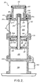
- and Figure 2 is a cross-sectional view of the shock isolator.
- Figure 1 illustrates shock protection of a radar antenna using the present invention. The system comprises six
telescopic shock isolators 10 andspacers 11 of the appropriate height for aplatform 12 to be protected, the platform having the antenna mounted thereon. All sixshock isolator 10/spacer 11 units are identical havingball joints 13 at each end and a screw type level adjuster 14. By changing the length of thespacer 11, theshock isolator 10 may be adapted to a variety of applications. Arranging theshock isolator 10/spacer 11 units in six triangles as shown in Figure 1 imparts kinematic rigidity as long as the length of eachshock isolator 10/spacer 11 unit is constant. Theshock isolators 10 yield axially when subjected to a compressive load above a predetermined release threshold and then return precisely to their original length when the compressive load falls below the predetermined release threshold. The original alignment of theplatform 12 is thereby accurately restored. - Referring now to Figure 2, the construction of each
shock isolator 10 will be described. Eachshock isolator 10 consists of a hollow piston 20 fitted within acylinder 21. The top of the piston 20 may be attached to aspacer 11 as in Figure 1 or directly to the platform or load to be isolated 22 as shown in Figure 2. Eachcylinder 21 is divided into three chambers: alatching chamber 23, abuffer chamber 24, and areserve air chamber 25. A hollowpiston guide tube 26 attached to the piston 20 supports abuffer piston head 28 and is open to thereserve air chamber 25. Alatching ledge 27 of the piston 20 contains aprimary gasket seal 34 which is a controlled confinement polymer of the crown and grooved type and is mechanically and chemically bonded to thepiston latching ledge 27. The portion of thepiston guide tube 26 passing through thelatching chamber 23 hasair bypass ports 29 which provide an air passage between thereserve air chamber 25 and thelatching chamber 23. In the latched position shown in Figure 2, allchambers air bypass ports 29, ableed orifice 30 in an intermediate cylinder head 31 which separates thelatching chamber 23 and thebuffer chamber 24, and ableed orifice 32 in a further intermediate cylinder head (43) which orifice connects thereserve air chamber 25 with thebuffer chamber 24. - Thus the
latching chamber 23 is defined by a primary cylinder head 44 and the intermediate cylinder head 31; thebuffer chamber 24 by the intermediate cylinder head 31 and the furtherintermediate cylinder head 43; and the reserve air chamber by the furtherintermediate cylinder head 43 and abaseplate 45 on which thecylinder 21 is mounted. - The
volume 33 between theprimary face seal 34 and the upper pistonrod running seal 35 is vented to the atmosphere through a pistonrod seal bypass 36. Thebuffer piston head 28 has a cup sea! 37 around its periphery and contains sixball check valves 38 and three deceleration control valves (not shown). - The primary souce of pressurised air for the
shock isolator 10 is contained in an integral high pressureair storage tank 39 at 2000 psig. (13788 x 103 Pa). Air is fed into thereserve air chamber 25 through aregulator 40 which provides a working pressure of 100 psig (689.4 x 10³ Pa) in theair reserve chamber 25. - Operation of the
shock isolator 10 will now be described. Theshock isolator 10 as shown in Figure 2 is in the pressurised latched state. Air pressure is uniform throughoutchambers primary seal 34 against cylinder banking surface 34a establishing a latching preload LL. If aload 22 of mass W/g is attached to the piston 20, the reaction force FR supplied by thecylinder 21 at the banking surface 34a is F = LL-W when the acceleration of the piston Ap = 0. If the banking surface 34a restraint were removed, the piston 20 would experience acceleration:
cylinder 21 acceleration less than piston 20 latching acceleration ApL, the piston 20 andcylinder 21 will remain in contact at the banking surface 34a. Atcylinder 21 acceleration greater than APL, the piston 20 will lag thecylinder 21. When the piston 20 displacement is sufficient to open thegasket seal 34, for example 0.015 inches (0.038 cms) to 0.030 inches (0.076 cms), pressurised air from thelatching chamber 23 will flow behind thepiston latching ledge 27 and the piston 20 acceleration will decrease slightly. The piston 20 is now in its unlatched state. Pressurised air will not escape because as theprimary seal 34 opens, the pistonrod bypass tube 36 moves past thepiston rod seal 35, thus preventing any escape of pressurised air. - Once unlatched, the piston 20 moves upward more slowly than does the
cylinder 21.Buffet chamber 24 is divided into an upper section 24a and alower section 24 by thepiston head 28 and theball check valves 38 and decelleration control valves are open.Tile cup seal 37 collapses and pressurised air moves freely between the upper 24a and lower 24 sections of thebuffer chamber 24. - In the illustrated preferred embodiment, the
latching chamber 23 is five inches (12.7 cms) in length including a one-inch (2-5 cm)overtravel zone 41 at each end. The diameter of theovertravel zone 41 just matches the diameter of the piston 20 and upon the piston 20 entering theovertravel zone 41, air pressure builds up because air is no longer spilling behind thelatching ledge 27. - Thus, the piston 20 is brought to a controlled stop before experiencing a hard stop against the intermediate cylinder head 31. When the piston 20 velocity and
cylinder 21 velocity are equal, the relative displacement of piston 20 andcylinder 21 will be at a maximum. - As the reset cycle begins, the piston 20 is moving faster than the
cylinder 21. Thecheck valves 38 and deceleration control valves close and thecup seal 37 presses against the walls of thecylinder 21 thereby sealing the upper section 24a of thebuffer chamber 24 except for a small amount of air passing through athrottle orifice 42. Pressure will continue to rise in the upper section 24a of thebuffer chamber 24 as the piston 20 moves upwards towards the latched position. By proper selection of the size of thethrottle orifice 42, the piston will arrive at the latched position shown in Figure 1 when thecylinder 21 and piston 20 have a near zero relative velocity. Once theprimary seal 34 contacts the banking surface 34a, theshock isolator 10 is latched and held in position by pressurised air within thelatching chamber 23.
Claims (4)
Applications Claiming Priority (2)
| Application Number | Priority Date | Filing Date | Title |
|---|---|---|---|
| US76922085A | 1985-08-26 | 1985-08-26 | |
| US769220 | 1985-08-26 |
Publications (2)
| Publication Number | Publication Date |
|---|---|
| EP0214754A1 EP0214754A1 (en) | 1987-03-18 |
| EP0214754B1 true EP0214754B1 (en) | 1989-08-09 |
Family
ID=25084832
Family Applications (1)
| Application Number | Title | Priority Date | Filing Date |
|---|---|---|---|
| EP19860305924 Expired EP0214754B1 (en) | 1985-08-26 | 1986-08-01 | Telescoping strut shock isolator |
Country Status (3)
| Country | Link |
|---|---|
| EP (1) | EP0214754B1 (en) |
| CA (1) | CA1274259A (en) |
| DE (1) | DE3664950D1 (en) |
Families Citing this family (1)
| Publication number | Priority date | Publication date | Assignee | Title |
|---|---|---|---|---|
| US5071108A (en) * | 1990-01-12 | 1991-12-10 | Newport Corporation | Pneumatic vibration isolation systems with automatic piston centering |
Family Cites Families (4)
| Publication number | Priority date | Publication date | Assignee | Title |
|---|---|---|---|---|
| FR2173498A5 (en) * | 1972-02-25 | 1973-10-05 | Vial Antoine | |
| AT350337B (en) * | 1977-06-17 | 1979-05-25 | Sticht Walter | SHOCK ABSORBER ARRANGEMENT, IN PARTICULAR FOR ASSEMBLY MACHINES |
| IT1119229B (en) * | 1979-10-17 | 1986-03-03 | Roberto Perlini | PNEUMATIC OR HYDROPNEUMATIC SUSPENSION PARTICULARLY FOR HEAVY VEHICLES |
| GB2116665A (en) * | 1982-02-11 | 1983-09-28 | L A G D Dr Santos | Dynamic energy dissipating pipe support with pneumatic damper |
-
1986
- 1986-04-24 CA CA000507454A patent/CA1274259A/en not_active Expired
- 1986-08-01 EP EP19860305924 patent/EP0214754B1/en not_active Expired
- 1986-08-01 DE DE8686305924T patent/DE3664950D1/en not_active Expired
Also Published As
| Publication number | Publication date |
|---|---|
| DE3664950D1 (en) | 1989-09-14 |
| CA1274259A (en) | 1990-09-18 |
| EP0214754A1 (en) | 1987-03-18 |
Similar Documents
| Publication | Publication Date | Title |
|---|---|---|
| US3459395A (en) | Shock isolating means | |
| US8763997B2 (en) | Helicopter landing gear damper | |
| EP4003835B1 (en) | Shock absorbing strut | |
| EP0607545B1 (en) | Shock absorber | |
| US5199690A (en) | Active vibration isolation system | |
| US4381857A (en) | Programmed oleo-pneumatic shock absorber | |
| US6615959B2 (en) | Damper with high dissipating power | |
| US5529152A (en) | Variable constant force hydraulic components and systems | |
| US6340153B1 (en) | Shock and acoustic mount | |
| EP2368066B1 (en) | Apparatus for improved vibration isolation | |
| CA1247666A (en) | Vehicle suspension system | |
| US4582303A (en) | Seal protecting construction for liquid spring | |
| US3040907A (en) | Hydraulic shock-absorber | |
| US2961204A (en) | Deceleration device | |
| US4815716A (en) | Telescoping strut shock isolator | |
| GB794354A (en) | Improvements in or relating to shock absorbers for aircraft | |
| CA2274463A1 (en) | Crashworthy landing gear shock | |
| US3747913A (en) | Fluid spring shock absorbers | |
| US4597548A (en) | Shock absorbing struts for aircraft landing gear | |
| EP0214754A1 (en) | Telescoping strut shock isolator | |
| GB2213905A (en) | Rapid extension shock absorber | |
| US20060086582A1 (en) | Semi-active isolator | |
| US4648490A (en) | Shock absorber | |
| US2809666A (en) | Surge arresters | |
| US4964491A (en) | System for limiting snap load intensity |
Legal Events
| Date | Code | Title | Description |
|---|---|---|---|
| PUAI | Public reference made under article 153(3) epc to a published international application that has entered the european phase |
Free format text: ORIGINAL CODE: 0009012 |
|
| AK | Designated contracting states |
Kind code of ref document: A1 Designated state(s): DE GB IT NL |
|
| 17P | Request for examination filed |
Effective date: 19870717 |
|
| 17Q | First examination report despatched |
Effective date: 19880413 |
|
| ITF | It: translation for a ep patent filed | ||
| GRAA | (expected) grant |
Free format text: ORIGINAL CODE: 0009210 |
|
| AK | Designated contracting states |
Kind code of ref document: B1 Designated state(s): DE GB IT NL |
|
| REF | Corresponds to: |
Ref document number: 3664950 Country of ref document: DE Date of ref document: 19890914 |
|
| RAP2 | Party data changed (patent owner data changed or rights of a patent transferred) |
Owner name: UNISYS CORPORATION |
|
| NLT2 | Nl: modifications (of names), taken from the european patent patent bulletin |
Owner name: UNISYS CORPORATION TE BLUE BELL, PENNSYLVANIE, VER |
|
| PLBE | No opposition filed within time limit |
Free format text: ORIGINAL CODE: 0009261 |
|
| STAA | Information on the status of an ep patent application or granted ep patent |
Free format text: STATUS: NO OPPOSITION FILED WITHIN TIME LIMIT |
|
| 26N | No opposition filed | ||
| PG25 | Lapsed in a contracting state [announced via postgrant information from national office to epo] |
Ref country code: DE Effective date: 19910501 |
|
| ITTA | It: last paid annual fee | ||
| PGFP | Annual fee paid to national office [announced via postgrant information from national office to epo] |
Ref country code: NL Payment date: 19930831 Year of fee payment: 8 |
|
| PG25 | Lapsed in a contracting state [announced via postgrant information from national office to epo] |
Ref country code: NL Effective date: 19950301 |
|
| NLV4 | Nl: lapsed or anulled due to non-payment of the annual fee | ||
| PGFP | Annual fee paid to national office [announced via postgrant information from national office to epo] |
Ref country code: GB Payment date: 19960710 Year of fee payment: 11 |
|
| PG25 | Lapsed in a contracting state [announced via postgrant information from national office to epo] |
Ref country code: GB Free format text: LAPSE BECAUSE OF NON-PAYMENT OF DUE FEES Effective date: 19970801 |
|
| GBPC | Gb: european patent ceased through non-payment of renewal fee |
Effective date: 19970801 |
|
| PG25 | Lapsed in a contracting state [announced via postgrant information from national office to epo] |
Ref country code: IT Free format text: LAPSE BECAUSE OF NON-PAYMENT OF DUE FEES;WARNING: LAPSES OF ITALIAN PATENTS WITH EFFECTIVE DATE BEFORE 2007 MAY HAVE OCCURRED AT ANY TIME BEFORE 2007. THE CORRECT EFFECTIVE DATE MAY BE DIFFERENT FROM THE ONE RECORDED. Effective date: 20050801 |