EP0213096A1 - Ride-on mower - Google Patents
Ride-on mower Download PDFInfo
- Publication number
- EP0213096A1 EP0213096A1 EP86850259A EP86850259A EP0213096A1 EP 0213096 A1 EP0213096 A1 EP 0213096A1 EP 86850259 A EP86850259 A EP 86850259A EP 86850259 A EP86850259 A EP 86850259A EP 0213096 A1 EP0213096 A1 EP 0213096A1
- Authority
- EP
- European Patent Office
- Prior art keywords
- axis
- engine
- section
- rear section
- steering
- Prior art date
- Legal status (The legal status is an assumption and is not a legal conclusion. Google has not performed a legal analysis and makes no representation as to the accuracy of the status listed.)
- Granted
Links
Images


Classifications
-
- A—HUMAN NECESSITIES
- A01—AGRICULTURE; FORESTRY; ANIMAL HUSBANDRY; HUNTING; TRAPPING; FISHING
- A01D—HARVESTING; MOWING
- A01D34/00—Mowers; Mowing apparatus of harvesters
- A01D34/01—Mowers; Mowing apparatus of harvesters characterised by features relating to the type of cutting apparatus
- A01D34/412—Mowers; Mowing apparatus of harvesters characterised by features relating to the type of cutting apparatus having rotating cutters
- A01D34/63—Mowers; Mowing apparatus of harvesters characterised by features relating to the type of cutting apparatus having rotating cutters having cutters rotating about a vertical axis
- A01D34/64—Mowers; Mowing apparatus of harvesters characterised by features relating to the type of cutting apparatus having rotating cutters having cutters rotating about a vertical axis mounted on a vehicle, e.g. a tractor, or drawn by an animal or a vehicle
- A01D2034/645—Lifting means for the cutter of the lawnmower mounted at the front of the vehicle for inspection and maintenance
-
- A—HUMAN NECESSITIES
- A01—AGRICULTURE; FORESTRY; ANIMAL HUSBANDRY; HUNTING; TRAPPING; FISHING
- A01D—HARVESTING; MOWING
- A01D2101/00—Lawn-mowers
Definitions
- This invention relates to a mower having a chassis with an engine and comprising a front and rear section, each section being provided with a pair of wheels, the front section supporting a cutting attachment, the front section and at least a part of the rear section being pivotally connected to each other so that they can be turned about a mainly vertical steering axis and about a mainly horizontal swinging axis.
- Mowers of the riding type are previously known. Such machines can be provided with front mounted cutting attachments and cutting attachments which are centrally placed between the front- and rearwheels respectively.
- the engine can be placed in front of or behind the driver and further there are front wheel- and rearwheel steering and driving.
- Each type has its own advantages and drawbacks.
- mowers with centrally placed cutting attachments generally have the drawback that the front wheel presses down the grass before it reaches the cutting attachment which means that parts of a lawn are badly cut.
- a mower having a front mounted cutting attachment, rear mounted engine and rear wheel steering gives a good survey of the cutting attachment and the surface to be cut whereas the drawback is a large turning radius since the steering angle is limited with the respect to the friction between the lawn and the steering wheels.
- a rear wheel driven machine with the engine at the rear, centrally placed cutting attachment and with front wheel steering gives advantages with respect to the transmission because of the short distance between the engine and driving wheels and cutting attachment respectively but gives an even large turning radius since the centrally placed cutting attachment creates a larges wheel basis then machines having front mounted attachments. In order to shorten the time during shunting in connection with turnings it is desirable that a machine has as short turning radius as possible.
- the chassis comprises two sections which are pivotally connected to each other half way between the front and rear wheels.
- the front section of the chassis supports the two front wheels which are mounted on separate shafts, the cutting attachment which is placed ahead of the front wheels and the operator.
- the rear section supports engine with gear box, differential gearing and rear shaft, the steering being effected by turning the rear section with respect to the front section about a vertical steering axis.
- the pivot point is in this machine so designed that turning the rear section with respect to the front section also can be effected about a swinging axis which is directed in the travelling direction of the mower and horisontally placed on the front section in order to make it possible for the wheels to follow irregularities on the ground.
- the purpose of this invention is to achieve a mower which gives maximum passability by reducing the turning radius with respect to known machines at the same time as the risk for slipping is reduced to minimum as is also the risk for tipping and where the other drawbacks refered to above are eliminated. This purpose is achieved with the device according to the invention as it is defined in the following claims.
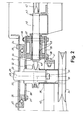
- figure 1 is a longitudinal vertical section of a device according to the invention whereas Fig. 2 is a longitudinal vertical section of the rear part of the device according to the invention and Fig. 3 is a vertical section of a modified embodiment according to the invention.
- the mower comprises a chassis generally denoted 10.
- the chassis has a front pair of wheels and a rear pair of wheels 11 and comprises two sections 12 and 13 respectively.
- the front section 12 supports a cutting attachment schematically denoted 14, a seat 15 for the driver, necessary manoeuvre devices and a battery 16, engine 17 and petrol tank 18.
- the rear section 13 supports a gear box 19 with differential gear and a rear shaft 20 which drives a rear pair of wheels 11.
- the rear part of the chassis front section 12 is shaped as a support plate 21 with a hole 22 through which the output shaft 23 of the engine extends vertically downwards.
- an outer ring 24 of a ball bearing with large diameter is fastened by means of several screws 25.
- the inner ring 26 of the ball bearing is by means of screws 27 connected to a turning plate 28.
- the turning plate moves about a steering axis 29 and has a hole through which the output shaft of the engine extends.
- the output shaft 23 of the engine at its lower part supports a hub 30 which has an upper pulley 32 with comparatively small diameter for driving the wheels of the mower the pulley being fixed to a sleeve 33 which is concentric to the output shaft 23 and which supports a lower pulley 34 with a comparatively large diameter intended to drive the cutting attachment.
- the pulleys 32 and 34 are fastened to the output shaft 23 of the engine by means of a bolt 35 and a washer 36.
- the turning plate 28 is turnable about the output shaft 23 of the engine and has a bearing holder 37 which by means of bolts 38 is fastened to the turning plate 28 as well as to a bracket 39 on which a steering plate 40 is provided by means of bolts 41.
- the steering plate 40 is via a wire connected to the steering wheel of the mower.
- a dowel 42 is turnable secured.
- the dowel extends horisontally rearwards and one of its ends has a clamp 43 which is an intergrated part of the rear section 13 of the chassis whereas its front end has a locking washer 44 which prevents the dowel from falling out of the bearing holder 37.
- the dowel rests in two sliding bearing 45 which are pressed into the bearing holder.
- the gear box has an input shaft 46 which is vertically placed and provided with a pulley 47 which is driven from said upper pulley 32 by means of a belt 48.
- the upper pulley 32 and the pulley 47 on the input shaft of the gear box are situated in the same horisontal plane as the dowel 42 in order to reduce the tendency of the belt to pull off the pulleys when turning is effected about the horisontal axis.
- the steering plate 40 By acting on the steering wheel the steering plate 40 will be turned so that the rear section 13 turns about the vertical shaft of the engine 23. Since the rear section 13 is comparatively short compared to the front section 12 and in combination with the position of the pivot 37, 42, 45 on the short chassis section, larger steering angles or larger variations between the ground pressure of the driving wheels can be allowed without the risk for tipping than in previously known arrangements which in turn means reduced turning radius. Any irregularities on the ground will as said above be taken up as a turning movement of the rear shaft about the horisontal longitudinal axis.
- the device shown in Fig. 3 differs from what has been shown in Fig. 1 mainly because the engine is placed on a supporting plate 49 which is a part of the rear section 13 of the chassis, the supporting plate 49 and engine 17 together being turnable about the vertical axis 50 coinsiding with the shaft of the engine.
- the supporting plate is via a swinging axis 51 fastened to one of two to each other linked parts 52, 53 which means that the rear shaft 20 may achieve different angle positions with respect to the horisontal plane.
- the turning plate moves about the vertical steering shaft 29 which coinsides with the motor shaft 23, the steering axis being placed considerably closer to the wheel axis of the rear section 13 than the wheel axis of the front section 12.
- the distance a between the steering axis 29 and the wheel axis of the rear section 13 is less than 1/3 of the distance b between the two wheel axis.
Abstract
Description
- This invention relates to a mower having a chassis with an engine and comprising a front and rear section, each section being provided with a pair of wheels, the front section supporting a cutting attachment, the front section and at least a part of the rear section being pivotally connected to each other so that they can be turned about a mainly vertical steering axis and about a mainly horizontal swinging axis.
- Mowers of the riding type are previously known. Such machines can be provided with front mounted cutting attachments and cutting attachments which are centrally placed between the front- and rearwheels respectively.
- The engine can be placed in front of or behind the driver and further there are front wheel- and rearwheel steering and driving. Each type has its own advantages and drawbacks. For instance mowers with centrally placed cutting attachments generally have the drawback that the front wheel presses down the grass before it reaches the cutting attachment which means that parts of a lawn are badly cut. A mower having a front mounted cutting attachment, rear mounted engine and rear wheel steering gives a good survey of the cutting attachment and the surface to be cut whereas the drawback is a large turning radius since the steering angle is limited with the respect to the friction between the lawn and the steering wheels. A rear wheel driven machine with the engine at the rear, centrally placed cutting attachment and with front wheel steering gives advantages with respect to the transmission because of the short distance between the engine and driving wheels and cutting attachment respectively but gives an even large turning radius since the centrally placed cutting attachment creates a larges wheel basis then machines having front mounted attachments. In order to shorten the time during shunting in connection with turnings it is desirable that a machine has as short turning radius as possible.
- In a type of machine which is a rather good compromise between different wishes the chassis comprises two sections which are pivotally connected to each other half way between the front and rear wheels. The front section of the chassis supports the two front wheels which are mounted on separate shafts, the cutting attachment which is placed ahead of the front wheels and the operator. The rear section supports engine with gear box, differential gearing and rear shaft, the steering being effected by turning the rear section with respect to the front section about a vertical steering axis. The pivot point is in this machine so designed that turning the rear section with respect to the front section also can be effected about a swinging axis which is directed in the travelling direction of the mower and horisontally placed on the front section in order to make it possible for the wheels to follow irregularities on the ground.
- Even if the machine described above in most respects has rather good characteristics, its turning radius is after all limited to something which corresponds to about 45° turn of angle of the rear section. This depends on that the rear wheels - with the reasonable length of the machine - when being further turned would get in touch with the front wheels and that further turning of the wheels would lead to too large variation in the ground pressure between the two driving wheels because of the position of the swinging axis. At a certain steering angle the ground pressure on the inner wheel becomes so small that driving ceases. The ground pressure of this wheel can even become negative that is the wheel is lifted from ground which causes the risk for tipping. Moreover the cutting attachment of this machine cannot be driven directly by one single belt from the engine since the distance between engine and cutting attachment changes with the steering angle. Further drawbacks are that there is a demand for operating devices on the engine following its movement and that a certain undesireable self guiding is achieved because the grass during cutting brakes the knifes wich causes a moment between the two sections of the machine.
- The purpose of this invention is to achieve a mower which gives maximum passability by reducing the turning radius with respect to known machines at the same time as the risk for slipping is reduced to minimum as is also the risk for tipping and where the other drawbacks refered to above are eliminated. This purpose is achieved with the device according to the invention as it is defined in the following claims.
- An embodiment of the invention will now be described with reference to the accompanying drawings where figure 1 is a longitudinal vertical section of a device according to the invention whereas Fig. 2 is a longitudinal vertical section of the rear part of the device according to the invention and Fig. 3 is a vertical section of a modified embodiment according to the invention.
- As appears from Fig. 1 and 2 the mower comprises a chassis generally denoted 10. The chassis has a front pair of wheels and a rear pair of
wheels 11 and comprises twosections front section 12 supports a cutting attachment schematically denoted 14, aseat 15 for the driver, necessary manoeuvre devices and abattery 16,engine 17 andpetrol tank 18. Therear section 13 supports agear box 19 with differential gear and arear shaft 20 which drives a rear pair ofwheels 11. - In order to support the
engines 17 the rear part of thechassis front section 12 is shaped as asupport plate 21 with ahole 22 through which theoutput shaft 23 of the engine extends vertically downwards. To the supportingplate 21 anouter ring 24 of a ball bearing with large diameter is fastened by means ofseveral screws 25. Theinner ring 26 of the ball bearing is by means ofscrews 27 connected to aturning plate 28. The turning plate moves about a steering axis 29 and has a hole through which the output shaft of the engine extends. Theoutput shaft 23 of the engine at its lower part supports ahub 30 which has anupper pulley 32 with comparatively small diameter for driving the wheels of the mower the pulley being fixed to a sleeve 33 which is concentric to theoutput shaft 23 and which supports alower pulley 34 with a comparatively large diameter intended to drive the cutting attachment. - The
pulleys output shaft 23 of the engine by means of abolt 35 and awasher 36. Thus, theturning plate 28 is turnable about theoutput shaft 23 of the engine and has abearing holder 37 which by means ofbolts 38 is fastened to theturning plate 28 as well as to abracket 39 on which asteering plate 40 is provided by means ofbolts 41. Thesteering plate 40 is via a wire connected to the steering wheel of the mower. In the bearing holder 37 adowel 42 is turnable secured. The dowel extends horisontally rearwards and one of its ends has aclamp 43 which is an intergrated part of therear section 13 of the chassis whereas its front end has alocking washer 44 which prevents the dowel from falling out of thebearing holder 37. The dowel rests in two sliding bearing 45 which are pressed into the bearing holder. - The gear box has an
input shaft 46 which is vertically placed and provided with apulley 47 which is driven from saidupper pulley 32 by means of abelt 48. - As appears from the figure the
upper pulley 32 and thepulley 47 on the input shaft of the gear box are situated in the same horisontal plane as thedowel 42 in order to reduce the tendency of the belt to pull off the pulleys when turning is effected about the horisontal axis. - By acting on the steering wheel the
steering plate 40 will be turned so that therear section 13 turns about the vertical shaft of theengine 23. Since therear section 13 is comparatively short compared to thefront section 12 and in combination with the position of thepivot - The device shown in Fig. 3 differs from what has been shown in Fig. 1 mainly because the engine is placed on a supporting
plate 49 which is a part of therear section 13 of the chassis, the supportingplate 49 andengine 17 together being turnable about thevertical axis 50 coinsiding with the shaft of the engine. The supporting plate is via aswinging axis 51 fastened to one of two to each other linkedparts 52, 53 which means that therear shaft 20 may achieve different angle positions with respect to the horisontal plane. - The turning plate moves about the vertical steering shaft 29 which coinsides with the
motor shaft 23, the steering axis being placed considerably closer to the wheel axis of therear section 13 than the wheel axis of thefront section 12. Preferably the distance a between the steering axis 29 and the wheel axis of therear section 13 is less than 1/3 of the distance b between the two wheel axis.
Claims (8)
Priority Applications (1)
| Application Number | Priority Date | Filing Date | Title |
|---|---|---|---|
| AT86850259T ATE63195T1 (en) | 1985-08-08 | 1986-07-16 | LAWN MOWER WITH RIDER SEAT. |
Applications Claiming Priority (2)
| Application Number | Priority Date | Filing Date | Title |
|---|---|---|---|
| SE8503747A SE454127B (en) | 1985-08-08 | 1985-08-08 | ACCESSIBLE Mower |
| SE8503747 | 1985-08-08 |
Publications (2)
| Publication Number | Publication Date |
|---|---|
| EP0213096A1 true EP0213096A1 (en) | 1987-03-04 |
| EP0213096B1 EP0213096B1 (en) | 1991-05-08 |
Family
ID=20361062
Family Applications (1)
| Application Number | Title | Priority Date | Filing Date |
|---|---|---|---|
| EP86850259A Expired - Lifetime EP0213096B1 (en) | 1985-08-08 | 1986-07-16 | Ride-on mower |
Country Status (11)
| Country | Link |
|---|---|
| US (1) | US4809489A (en) |
| EP (1) | EP0213096B1 (en) |
| JP (1) | JPH0671373B2 (en) |
| AT (1) | ATE63195T1 (en) |
| AU (1) | AU594063B2 (en) |
| CA (1) | CA1285143C (en) |
| DE (1) | DE3679120D1 (en) |
| DK (1) | DK161004C (en) |
| FI (1) | FI81711C (en) |
| NZ (1) | NZ216778A (en) |
| SE (1) | SE454127B (en) |
Cited By (6)
| Publication number | Priority date | Publication date | Assignee | Title |
|---|---|---|---|---|
| EP0630553A1 (en) * | 1993-06-22 | 1994-12-28 | Deere & Company | Implement drive for a vehicle-implement combination |
| EP0966876A1 (en) | 1998-06-26 | 1999-12-29 | Aktiebolaget Electrolux | Device for a riding mower |
| US6098386A (en) * | 1998-03-27 | 2000-08-08 | Kanzaki Kokyukoki Mfg. Co., Ltd. | Riding lawn mower and transmission for the same |
| EP1068785A1 (en) * | 1999-07-15 | 2001-01-17 | ANTONIO CARRARO S.p.A. | Gardening vehicle, such as a lawnmower or the like |
| EP1413498A3 (en) * | 2002-10-22 | 2006-05-24 | Kanzaki Kokyukoki Mfg. Co., Ltd. | Four-wheel drive vehicle |
| EP3106014A1 (en) | 2015-06-19 | 2016-12-21 | GGP Italy S.p.A. | Lift apparatus of a lawn mower cutting deck |
Families Citing this family (22)
| Publication number | Priority date | Publication date | Assignee | Title |
|---|---|---|---|---|
| SE454039B (en) * | 1985-09-27 | 1988-03-28 | Husqvarna Ab | ACCESSIBLE Mower |
| SE456712B (en) * | 1985-09-27 | 1988-10-31 | Husqvarna Ab | BEAUTIFUL GRAY CUTTERS |
| DE3772481D1 (en) * | 1986-07-25 | 1991-10-02 | Etesia | LAWN MOWER WITH DRIVER SEAT. |
| JPH0620353Y2 (en) * | 1987-08-17 | 1994-06-01 | セイレイ工業株式会社 | Mower |
| US4969319A (en) * | 1988-09-16 | 1990-11-13 | Deere & Company | Engine/transaxle combination |
| US5187925A (en) * | 1991-06-14 | 1993-02-23 | Deere & Company | Mower deck lift handle mechanism |
| US5161353A (en) * | 1991-08-21 | 1992-11-10 | Deweze Manufacturing, Inc. | Slope mower with improved blade housing floatation |
| JP2996317B2 (en) * | 1991-09-19 | 1999-12-27 | 株式会社 神崎高級工機製作所 | Axle drive of work vehicle |
| JPH05185961A (en) * | 1992-01-10 | 1993-07-27 | Honda Motor Co Ltd | Cover structure of vehicle |
| SE9401745L (en) * | 1994-05-20 | 1995-03-27 | Stiga Ab | Control device in a riding lawnmower and included link elements for interconnecting transmission chains |
| IL113913A (en) | 1995-05-30 | 2000-02-29 | Friendly Machines Ltd | Navigation method and system |
| US5742975A (en) * | 1996-05-06 | 1998-04-28 | Windsor Industries, Inc. | Articulated floor scrubber |
| US6364041B1 (en) | 1998-10-30 | 2002-04-02 | The Toro Company | Mid-axle suspension |
| US6131380A (en) * | 1998-11-27 | 2000-10-17 | Browning; Albert | Floating deck mower with gravity actuated brake |
| US6354615B1 (en) | 1999-02-08 | 2002-03-12 | The Toro Company | Vehicle having a torsional suspension and torsional joint |
| US6425452B1 (en) | 2000-07-26 | 2002-07-30 | Venture Products, Inc. | Control system for all-wheel drive vehicle |
| AU2011372806B2 (en) | 2011-07-14 | 2015-07-16 | Husqvarna Ab | Battery powered lawn care vehicle with efficient drive controller |
| CN103813933B (en) | 2011-07-14 | 2017-09-19 | 胡斯华纳有限公司 | Battery powered lawn-care car with drive efficiency indicator |
| EP2731821B1 (en) * | 2011-07-14 | 2018-01-03 | Husqvarna Ab | Riding lawn mower including battery powered drive system |
| WO2013009322A1 (en) | 2011-07-14 | 2013-01-17 | Husqvarna Ab | Riding lawn mower including distributed battery system |
| CN110352004B (en) * | 2017-04-04 | 2022-02-22 | 胡斯华纳有限公司 | Cutting deck height adjustment system for riding lawn maintenance vehicle |
| EP3780933B1 (en) * | 2018-09-14 | 2023-11-08 | Husqvarna Ab | Multi-position locking mechanism for a riding lawn care vehicle |
Citations (3)
| Publication number | Priority date | Publication date | Assignee | Title |
|---|---|---|---|---|
| US2996867A (en) * | 1959-04-13 | 1961-08-22 | Williams Chester | Riding tractor mower |
| US4084395A (en) * | 1974-11-01 | 1978-04-18 | Nannen William G | Working vehicle |
| FR2534442A1 (en) * | 1982-10-19 | 1984-04-20 | Masquelier Ets | Self-propelled lawnmower |
Family Cites Families (13)
| Publication number | Priority date | Publication date | Assignee | Title |
|---|---|---|---|---|
| NL289954A (en) * | ||||
| GB478857A (en) * | 1936-01-29 | 1938-01-26 | Zd Y Tatra Akciova Spolecnost | Improvements in articulated motor vehicles |
| US2582177A (en) * | 1948-06-04 | 1952-01-08 | Max B Swisher | Powered caster wheel for vehicles |
| US3187821A (en) * | 1960-08-08 | 1965-06-08 | Simplicity Mfg Company | Tractor and power driven implement mounted thereon |
| US3110352A (en) * | 1961-09-15 | 1963-11-12 | Roscoe B Mcclarnon | Wheeled vehicle steering device |
| US3299982A (en) * | 1964-09-14 | 1967-01-24 | Fmc Corp | Articulated vehicle with pivotable frame steering |
| JPS5490726A (en) * | 1977-12-27 | 1979-07-18 | Komatsu Ltd | Straight motion assisting device for construction vehicle |
| JPS587193U (en) * | 1981-07-03 | 1983-01-18 | 株式会社河合楽器製作所 | electronic musical instruments |
| JPS5854379U (en) * | 1981-10-09 | 1983-04-13 | 株式会社クボタ | Passenger transport vehicle |
| JPS58136558A (en) * | 1982-02-08 | 1983-08-13 | Kubota Ltd | Service car |
| US4487006A (en) * | 1983-04-15 | 1984-12-11 | Scag Dane T | Lawn mower |
| SE454039B (en) * | 1985-09-27 | 1988-03-28 | Husqvarna Ab | ACCESSIBLE Mower |
| SE456712B (en) * | 1985-09-27 | 1988-10-31 | Husqvarna Ab | BEAUTIFUL GRAY CUTTERS |
-
1985
- 1985-08-08 SE SE8503747A patent/SE454127B/en unknown
-
1986
- 1986-07-02 AU AU59483/86A patent/AU594063B2/en not_active Expired
- 1986-07-07 CA CA000513211A patent/CA1285143C/en not_active Expired - Lifetime
- 1986-07-08 NZ NZ216778A patent/NZ216778A/en unknown
- 1986-07-16 EP EP86850259A patent/EP0213096B1/en not_active Expired - Lifetime
- 1986-07-16 DE DE8686850259T patent/DE3679120D1/en not_active Expired - Lifetime
- 1986-07-16 AT AT86850259T patent/ATE63195T1/en not_active IP Right Cessation
- 1986-08-04 DK DK371286A patent/DK161004C/en not_active IP Right Cessation
- 1986-08-07 JP JP61184344A patent/JPH0671373B2/en not_active Expired - Lifetime
- 1986-08-07 FI FI863237A patent/FI81711C/en not_active IP Right Cessation
-
1988
- 1988-01-14 US US07/144,726 patent/US4809489A/en not_active Expired - Lifetime
Patent Citations (3)
| Publication number | Priority date | Publication date | Assignee | Title |
|---|---|---|---|---|
| US2996867A (en) * | 1959-04-13 | 1961-08-22 | Williams Chester | Riding tractor mower |
| US4084395A (en) * | 1974-11-01 | 1978-04-18 | Nannen William G | Working vehicle |
| FR2534442A1 (en) * | 1982-10-19 | 1984-04-20 | Masquelier Ets | Self-propelled lawnmower |
Non-Patent Citations (1)
| Title |
|---|
| ENGINEERING, vol. 208, 25th July 1969, pages 80,81; R. LIVESEY: "Young designer cuts the grass" * |
Cited By (10)
| Publication number | Priority date | Publication date | Assignee | Title |
|---|---|---|---|---|
| EP0630553A1 (en) * | 1993-06-22 | 1994-12-28 | Deere & Company | Implement drive for a vehicle-implement combination |
| US6098386A (en) * | 1998-03-27 | 2000-08-08 | Kanzaki Kokyukoki Mfg. Co., Ltd. | Riding lawn mower and transmission for the same |
| EP0966876A1 (en) | 1998-06-26 | 1999-12-29 | Aktiebolaget Electrolux | Device for a riding mower |
| US6341480B1 (en) | 1998-06-26 | 2002-01-29 | Aktiebolaget Electrolux | Cutting unit for a riding mower |
| EP1068785A1 (en) * | 1999-07-15 | 2001-01-17 | ANTONIO CARRARO S.p.A. | Gardening vehicle, such as a lawnmower or the like |
| US6604346B1 (en) | 1999-07-15 | 2003-08-12 | Antonio Carraro S.P.A. | Gardening vehicle such as a lawn-mower or the like |
| EP1413498A3 (en) * | 2002-10-22 | 2006-05-24 | Kanzaki Kokyukoki Mfg. Co., Ltd. | Four-wheel drive vehicle |
| US7090045B2 (en) | 2002-10-22 | 2006-08-15 | Hideaki Okada | Four wheel-drive vehicle |
| US7261178B2 (en) | 2002-10-22 | 2007-08-28 | Hideaki Okada | Four wheel-drive vehicle |
| EP3106014A1 (en) | 2015-06-19 | 2016-12-21 | GGP Italy S.p.A. | Lift apparatus of a lawn mower cutting deck |
Also Published As
| Publication number | Publication date |
|---|---|
| FI81711C (en) | 1990-12-10 |
| SE454127B (en) | 1988-04-11 |
| JPS6342616A (en) | 1988-02-23 |
| DE3679120D1 (en) | 1991-06-13 |
| EP0213096B1 (en) | 1991-05-08 |
| US4809489A (en) | 1989-03-07 |
| SE8503747L (en) | 1987-02-09 |
| DK161004B (en) | 1991-05-21 |
| FI863237A0 (en) | 1986-08-07 |
| ATE63195T1 (en) | 1991-05-15 |
| AU594063B2 (en) | 1990-03-01 |
| DK371286D0 (en) | 1986-08-04 |
| SE8503747D0 (en) | 1985-08-08 |
| FI81711B (en) | 1990-08-31 |
| CA1285143C (en) | 1991-06-25 |
| AU5948386A (en) | 1987-02-12 |
| FI863237A (en) | 1987-02-09 |
| DK161004C (en) | 1991-10-28 |
| DK371286A (en) | 1987-02-09 |
| JPH0671373B2 (en) | 1994-09-14 |
| NZ216778A (en) | 1988-06-30 |
Similar Documents
| Publication | Publication Date | Title |
|---|---|---|
| EP0213096A1 (en) | Ride-on mower | |
| US5042238A (en) | Riding lawn mower | |
| US4887686A (en) | Working vehicle | |
| US3059397A (en) | Vehicle belt drive | |
| US11864492B2 (en) | Implement drive system and grounds maintenance vehicle incorporating same | |
| US4295326A (en) | Self-propelled flail blade lawn mower | |
| US3934670A (en) | Vehicle for propulsion of gardening implements and the like | |
| US4237991A (en) | Self-propelled lawn mower | |
| JP2000153771A (en) | Crawler type working vehicle | |
| JP3652457B2 (en) | Mobile farm machine | |
| WO1991001240A1 (en) | Riding lawn mower | |
| JPH1076970A (en) | Sulky lawn mower | |
| JPH0637640Y2 (en) | Combine speed controller | |
| JPS592347Y2 (en) | Belt transmission to work equipment | |
| GB1271658A (en) | Rotary mower | |
| US2842927A (en) | Automotive rideable mowing machine | |
| JPH0619391Y2 (en) | Work vehicle | |
| JPH0675446B2 (en) | Walking mower | |
| JP3429501B2 (en) | Work vehicle | |
| JPH079741Y2 (en) | Four-wheel drive vehicle | |
| JPS6024120Y2 (en) | Self-propelled straw cutter | |
| JP2626639B2 (en) | Farm work machine | |
| JPH0618825Y2 (en) | Traveling device for self-propelled work vehicle | |
| JP2004024070A (en) | Power vehicle | |
| SU1242035A1 (en) | Method of treatment of polyposis of cribrate sinus |
Legal Events
| Date | Code | Title | Description |
|---|---|---|---|
| PUAI | Public reference made under article 153(3) epc to a published international application that has entered the european phase |
Free format text: ORIGINAL CODE: 0009012 |
|
| AK | Designated contracting states |
Kind code of ref document: A1 Designated state(s): AT DE FR GB IT SE |
|
| 17P | Request for examination filed |
Effective date: 19870723 |
|
| 17Q | First examination report despatched |
Effective date: 19890720 |
|
| GRAA | (expected) grant |
Free format text: ORIGINAL CODE: 0009210 |
|
| AK | Designated contracting states |
Kind code of ref document: B1 Designated state(s): AT DE FR GB IT SE |
|
| REF | Corresponds to: |
Ref document number: 63195 Country of ref document: AT Date of ref document: 19910515 Kind code of ref document: T |
|
| REF | Corresponds to: |
Ref document number: 3679120 Country of ref document: DE Date of ref document: 19910613 |
|
| ITF | It: translation for a ep patent filed |
Owner name: PROPRIA PROTEZIONE PROPR. IND. |
|
| ET | Fr: translation filed | ||
| PLBE | No opposition filed within time limit |
Free format text: ORIGINAL CODE: 0009261 |
|
| STAA | Information on the status of an ep patent application or granted ep patent |
Free format text: STATUS: NO OPPOSITION FILED WITHIN TIME LIMIT |
|
| 26N | No opposition filed | ||
| EAL | Se: european patent in force in sweden |
Ref document number: 86850259.2 |
|
| REG | Reference to a national code |
Ref country code: GB Ref legal event code: IF02 |
|
| PGFP | Annual fee paid to national office [announced via postgrant information from national office to epo] |
Ref country code: SE Payment date: 20050706 Year of fee payment: 20 |
|
| PGFP | Annual fee paid to national office [announced via postgrant information from national office to epo] |
Ref country code: FR Payment date: 20050708 Year of fee payment: 20 |
|
| PGFP | Annual fee paid to national office [announced via postgrant information from national office to epo] |
Ref country code: AT Payment date: 20050713 Year of fee payment: 20 Ref country code: GB Payment date: 20050713 Year of fee payment: 20 |
|
| PGFP | Annual fee paid to national office [announced via postgrant information from national office to epo] |
Ref country code: DE Payment date: 20050714 Year of fee payment: 20 |
|
| PGFP | Annual fee paid to national office [announced via postgrant information from national office to epo] |
Ref country code: IT Payment date: 20050728 Year of fee payment: 20 |
|
| PG25 | Lapsed in a contracting state [announced via postgrant information from national office to epo] |
Ref country code: GB Free format text: LAPSE BECAUSE OF EXPIRATION OF PROTECTION Effective date: 20060715 |
|
| REG | Reference to a national code |
Ref country code: GB Ref legal event code: PE20 |
|
| EUG | Se: european patent has lapsed |