EP0212864A2 - Coaxial couplers - Google Patents
Coaxial couplers Download PDFInfo
- Publication number
- EP0212864A2 EP0212864A2 EP86305728A EP86305728A EP0212864A2 EP 0212864 A2 EP0212864 A2 EP 0212864A2 EP 86305728 A EP86305728 A EP 86305728A EP 86305728 A EP86305728 A EP 86305728A EP 0212864 A2 EP0212864 A2 EP 0212864A2
- Authority
- EP
- European Patent Office
- Prior art keywords
- waveguide
- fibre
- predetermined wavelength
- power
- light energy
- Prior art date
- Legal status (The legal status is an assumption and is not a legal conclusion. Google has not performed a legal analysis and makes no representation as to the accuracy of the status listed.)
- Withdrawn
Links
Images

Classifications
-
- G—PHYSICS
- G02—OPTICS
- G02B—OPTICAL ELEMENTS, SYSTEMS OR APPARATUS
- G02B6/00—Light guides; Structural details of arrangements comprising light guides and other optical elements, e.g. couplings
- G02B6/02—Optical fibres with cladding with or without a coating
- G02B6/036—Optical fibres with cladding with or without a coating core or cladding comprising multiple layers
- G02B6/03616—Optical fibres characterised both by the number of different refractive index layers around the central core segment, i.e. around the innermost high index core layer, and their relative refractive index difference
- G02B6/03638—Optical fibres characterised both by the number of different refractive index layers around the central core segment, i.e. around the innermost high index core layer, and their relative refractive index difference having 3 layers only
- G02B6/03644—Optical fibres characterised both by the number of different refractive index layers around the central core segment, i.e. around the innermost high index core layer, and their relative refractive index difference having 3 layers only arranged - + -
-
- G—PHYSICS
- G02—OPTICS
- G02B—OPTICAL ELEMENTS, SYSTEMS OR APPARATUS
- G02B6/00—Light guides; Structural details of arrangements comprising light guides and other optical elements, e.g. couplings
- G02B6/24—Coupling light guides
- G02B6/255—Splicing of light guides, e.g. by fusion or bonding
- G02B6/2552—Splicing of light guides, e.g. by fusion or bonding reshaping or reforming of light guides for coupling using thermal heating, e.g. tapering, forming of a lens on light guide ends
-
- G—PHYSICS
- G02—OPTICS
- G02B—OPTICAL ELEMENTS, SYSTEMS OR APPARATUS
- G02B6/00—Light guides; Structural details of arrangements comprising light guides and other optical elements, e.g. couplings
- G02B6/24—Coupling light guides
- G02B6/26—Optical coupling means
- G02B6/28—Optical coupling means having data bus means, i.e. plural waveguides interconnected and providing an inherently bidirectional system by mixing and splitting signals
- G02B6/2804—Optical coupling means having data bus means, i.e. plural waveguides interconnected and providing an inherently bidirectional system by mixing and splitting signals forming multipart couplers without wavelength selective elements, e.g. "T" couplers, star couplers
- G02B6/2821—Optical coupling means having data bus means, i.e. plural waveguides interconnected and providing an inherently bidirectional system by mixing and splitting signals forming multipart couplers without wavelength selective elements, e.g. "T" couplers, star couplers using lateral coupling between contiguous fibres to split or combine optical signals
- G02B6/2835—Optical coupling means having data bus means, i.e. plural waveguides interconnected and providing an inherently bidirectional system by mixing and splitting signals forming multipart couplers without wavelength selective elements, e.g. "T" couplers, star couplers using lateral coupling between contiguous fibres to split or combine optical signals formed or shaped by thermal treatment, e.g. couplers
-
- G—PHYSICS
- G02—OPTICS
- G02B—OPTICAL ELEMENTS, SYSTEMS OR APPARATUS
- G02B6/00—Light guides; Structural details of arrangements comprising light guides and other optical elements, e.g. couplings
- G02B6/02—Optical fibres with cladding with or without a coating
- G02B6/036—Optical fibres with cladding with or without a coating core or cladding comprising multiple layers
- G02B6/03605—Highest refractive index not on central axis
- G02B6/03611—Highest index adjacent to central axis region, e.g. annular core, coaxial ring, centreline depression affecting waveguiding
Definitions
- the present invention relates to coaxial waveguide couplers.
- the tubular waveguide is separated form the core by a cladding layer with a refractive index which is depressed relative to the refractive index of both the core and tubular waveguides.
- the refractive index of the core may be elevated relative to the refractive index of the tubular waveguide or they may be of the same magnitude.
- the coupler is phase-matched at one wavelength only, due to the different dispersion characteristics of the rod waveguide and the tubular waveguide. Therefore, in order to fabricate a coaxial coupler for a specific wavelength, strict dimensional and refractive index control must be provided to ensure that the two waveguides are precisely phase-matched at the wavelength of interest so that light energy at that frequency is coupled from one waveguide to the other with minimum power loss. The required tolerances are generally better than 1% and this results in high production costs and large failure rates.
- the present invention provides a method of producing.
- a coaxial coupler which comprises an optical fibre defining a rod waveguide surrounded by a tubular waveguide and which is adapted to couple light energy at a predetermined wavelength from one said waveguide to the other said waveguide, the method comprising the steps of elongating a portion of the optical fibre to reduce the dimensions of the portion while light energy of the predetermined wavelength is being propagated along one waveguide, monitoring the power transmitted at said predetermined wavelength through the reduced portion of the coupler in one of said waveguides, and stopping the elongation when the monitored power indicates that light energy of the predetermined wavelength is being coupled from said one waveguide to the other.
- the method of the inventon is advantageous in that it is always possible, starting from an optical fibre of approximately the correct refractive index profile and dimensions, to produce a coupler which is operable at the required wavelength. Since it is possible to produce the initial optical fibre to a relatively low tolerance, the production costs for the coupler can be considerably reduced.
- the invention further provides apparatus for producing a coaxial ocupler for coupling light energy of a predetermined wavelength from a rod waveguide to a surrounding tubular waveguide in an optical fibre, comprising a source of radiation at the predtermined wavelength, means for coupling light from the source to the optical fibre so that light of the predetermined wavelength is initially propagated in one waveguide only, means for elongating a portion of the optical fibre, means for monitoring the power propagated at the predetermined wavelength through one of said waveguides, and means for controlling the elongating means in response to the output of the power monitoring means.
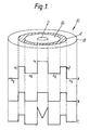
- a coaxial coupler is produced from an optical fibre having a refractive index profile as illustrated in Figure 1.
- the optical fibre defines two waveguides, a central rod waveguide which is defined by the core 2 of the fibre, and a coaxial tubular waveguide 4.
- the refractive indices n 1 , n 1 1 , of the rod and tubular waveguides are elevated relative to the refractive indices n 2 , n 3 of the intermediate cladding layer 6 and the outer coating layer 8.
- the dimensions and refractive indices n 1 of the rod waveguide and the tubular waveguide are selected such that each will support at least one transmission mode at the design wavelength which may be, say, 1.33 or 1.55 micrometres.
- Plots B and C in Figure 1 show other typical refractive index profiles for optical fibre coaxial couplers.
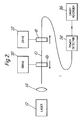
- the apparatus of Figure 2 comprises a laser light source producing radiation at the design wavelength. This radiation is passed through a lens 14 to focus it onto the cleaved face of the core 2 of the fibre 10 so that light is propagated along the core of the fibre. Normally the fibre will be surrounded by an acrylate jacket which will strip any modes which start to propagate in the tubular waveguide. If such a jacket is not provided the fibre may pass through a bath of index matching fluid which will prevent light propagation along the tubular waveguide.
- the fibre 10 is clamped at two spaced points along its length by clamps 16 and 18.
- Each clamp is provided with a motorised driver 20, 22 to enable the clamps to be pulled away from each other to taper the portion of the fibre between them.
- the drives are precisely controlled so that fibre extension of the order of lcm can be achieved and the extension stopped at a desired point to an accuracy of less than lmm.
- the clamps may be positioned vertically one above the other so that gravity can assist the tapering process.
- An epoxy-butane flame (not shown) is used to heat the fibre while the taper between the clamps is elongated.
- the end of the fibre 10 is coupled to a power detector 24 which is connected to a chart recorder. If this is not the case then the power detection is provided by a microscope coupled to a vidicon camera. The power detector or microscope is focused so as to detect the power propagated along the core 2 of the optical fibre 10. If the acrylate jacket does not strip modes propagating in the tubular waveguide, a further bath of index matching fluid is provided after clamp 18 to avoid light propagating in the tubular waveguide affecting the power detector.
- a typical plot produced on the chart recorder 26 is shown in Figure 3.
- the plot comprises a level section 30 where a constant amount of power is being received. This is indicative of the power launched from the laser into the core being propagated along the core with little or no coupling of power into the tubular waveguide 4.
- the received power oscillates increasingly rapidly between a series of minima 32, 34, 36 where little power is being received through the core.
- minima correspond to extensions of the fibre at which the tapered portion of the fibre 10 between the clamps 16, 18 is so dimensioned that there is complete energy exchange between the two waveguides.
- the plot produced in Figure 3 has been shown for a considerable extension of the fibre between the clamps.
- the drive to the clamps is stopped when the recorder reaches one of the minima 34, 36, or maxima 37, 38, 39 or anywhere in between depending on the application.
- the taper can be stopped at other than one of the minima in order to produce the required ratio of energy transfer between the waveguides.
- the operation of the coaxial coupler produced by this tapered waveguide can be considered as analogous to a three section coupler where the mismatch 0 ) between the propagation constants in each section alternates in sign.
- the three sections of the present coupler can be identified as shown in Figure 4.
- the sign of the difference between the propagation constants of the two waveguides changes between the outer portions of the taper and the central, thinnest, portion of the tapered portion.
- a description of the mathematics of three section ⁇ couplers can be found in an article entitled "Switched Directional Couplers with Alternating ⁇ by Herwig Kogelnik and Ronald V Schmidt in IEEE Journal of Quantum Electronics, Volume QE-12, No. 7, July 1976.
- This article relates to couplers in which the mismatch is produced by applying electrodes with alternating potential differences across them to the coupled waveguides.
- the dimensional variation of the tapered portion can be considered to produce a similar effect.
Landscapes
- Physics & Mathematics (AREA)
- General Physics & Mathematics (AREA)
- Optics & Photonics (AREA)
- Engineering & Computer Science (AREA)
- Plasma & Fusion (AREA)
- Manufacture, Treatment Of Glass Fibers (AREA)
- Optical Integrated Circuits (AREA)
- Mechanical Coupling Of Light Guides (AREA)
Abstract
Description
- The present invention relates to coaxial waveguide couplers.
- In certain applications it is desirable to transfer all or part of the light energy being transmitted along a rod waveguide defined by the core of an optical fibre to a coaxial tubular waveguide surrounding the core. The tubular waveguide is separated form the core by a cladding layer with a refractive index which is depressed relative to the refractive index of both the core and tubular waveguides. The refractive index of the core may be elevated relative to the refractive index of the tubular waveguide or they may be of the same magnitude.
- For such a coaxial coupler structure, it is found that the coupler is phase-matched at one wavelength only, due to the different dispersion characteristics of the rod waveguide and the tubular waveguide. Therefore, in order to fabricate a coaxial coupler for a specific wavelength, strict dimensional and refractive index control must be provided to ensure that the two waveguides are precisely phase-matched at the wavelength of interest so that light energy at that frequency is coupled from one waveguide to the other with minimum power loss. The required tolerances are generally better than 1% and this results in high production costs and large failure rates.
- It would therefore be desirable to produce a coaxial coupler by means of a method which did not impose such high tolerance requirements.
- Accordingly, the present invention provides a method of producing. a coaxial coupler which comprises an optical fibre defining a rod waveguide surrounded by a tubular waveguide and which is adapted to couple light energy at a predetermined wavelength from one said waveguide to the other said waveguide, the method comprising the steps of elongating a portion of the optical fibre to reduce the dimensions of the portion while light energy of the predetermined wavelength is being propagated along one waveguide, monitoring the power transmitted at said predetermined wavelength through the reduced portion of the coupler in one of said waveguides, and stopping the elongation when the monitored power indicates that light energy of the predetermined wavelength is being coupled from said one waveguide to the other.
- The method of the inventon is advantageous in that it is always possible, starting from an optical fibre of approximately the correct refractive index profile and dimensions, to produce a coupler which is operable at the required wavelength. Since it is possible to produce the initial optical fibre to a relatively low tolerance, the production costs for the coupler can be considerably reduced.
- The invention further provides apparatus for producing a coaxial ocupler for coupling light energy of a predetermined wavelength from a rod waveguide to a surrounding tubular waveguide in an optical fibre, comprising a source of radiation at the predtermined wavelength, means for coupling light from the source to the optical fibre so that light of the predetermined wavelength is initially propagated in one waveguide only, means for elongating a portion of the optical fibre, means for monitoring the power propagated at the predetermined wavelength through one of said waveguides, and means for controlling the elongating means in response to the output of the power monitoring means.
- Methods and apparatus according to the invention for producing a coaxial coupler will now be described, by way of example only, with reference to the accompanying diagrammatic drawings, in which:
- Figure 1 shows various refractive index profiles taken across the diameter of optical fibres suitable for producing coaxial couplers in accordance with the present invention;
- Figure 2 shows a diagrammatic representation of the apparatus;
- Figure 3 shows a plot of the transmitted power against the extension of the fibre; and
- Figure 4 is a diagram representing a section through a tapered portion of the waveguide for explaining the operation of the coupler.
- A coaxial coupler is produced from an optical fibre having a refractive index profile as illustrated in Figure 1. The optical fibre defines two waveguides, a central rod waveguide which is defined by the
core 2 of the fibre, and a coaxialtubular waveguide 4. As illustrated in plot A of Figure 1, the refractive indices n1, n1 1, of the rod and tubular waveguides are elevated relative to the refractive indices n2, n3 of the intermediate cladding layer 6 and the outer coating layer 8. The dimensions and refractive indices n1 of the rod waveguide and the tubular waveguide are selected such that each will support at least one transmission mode at the design wavelength which may be, say, 1.33 or 1.55 micrometres. Plots B and C in Figure 1 show other typical refractive index profiles for optical fibre coaxial couplers. - Light energy at the design wavelength will only be coupled from the rod waveguide to the tubular waveguide if there is precise phase-matching at this wavelength between the modes propagated in the two waveguides. Phase-matching depends critically on the refractive indexes and dimensions of the fibre profile. In most cases a fibre produced to have the required profile will not, in fact, be precisely phase-matched at the design wavelength. In order to produce the required phase-matching at the desired wavelength the
fibre 10 is placed in the apparatus illustrated in Figure 2 to taper it over a portion of its length to produce three regions of the fibre of opposite phase and mismatch at the design wavelength, is so that light energy launched into one of the waveguides is substantially completely coupled to the other waveguide. - The apparatus of Figure 2 comprises a laser light source producing radiation at the design wavelength. This radiation is passed through a
lens 14 to focus it onto the cleaved face of thecore 2 of thefibre 10 so that light is propagated along the core of the fibre. Normally the fibre will be surrounded by an acrylate jacket which will strip any modes which start to propagate in the tubular waveguide. If such a jacket is not provided the fibre may pass through a bath of index matching fluid which will prevent light propagation along the tubular waveguide. - The
fibre 10 is clamped at two spaced points along its length byclamps motorised driver - Where the fibre is a depressed cladding fibre, that is, where n2 is less than n3 as shown in profile C of Figure 1, the end of the
fibre 10 is coupled to apower detector 24 which is connected to a chart recorder. If this is not the case then the power detection is provided by a microscope coupled to a vidicon camera. The power detector or microscope is focused so as to detect the power propagated along thecore 2 of theoptical fibre 10. If the acrylate jacket does not strip modes propagating in the tubular waveguide, a further bath of index matching fluid is provided afterclamp 18 to avoid light propagating in the tubular waveguide affecting the power detector. - A typical plot produced on the
chart recorder 26 is shown in Figure 3. The plot comprises alevel section 30 where a constant amount of power is being received. This is indicative of the power launched from the laser into the core being propagated along the core with little or no coupling of power into thetubular waveguide 4. After thislevel section 30 the received power oscillates increasingly rapidly between a series ofminima fibre 10 between theclamps minima maxima - If it is desired to produce a coupler which couples a desired proportion of the energy from one waveguide to the other, the taper can be stopped at other than one of the minima in order to produce the required ratio of energy transfer between the waveguides.
- The operation of the coaxial coupler produced by this tapered waveguide can be considered as analogous to a three section coupler where the mismatch 0 ) between the propagation constants in each section alternates in sign. The three sections of the present coupler can be identified as shown in Figure 4. The sign of the difference between the propagation constants of the two waveguides changes between the outer portions of the taper and the central, thinnest, portion of the tapered portion. A description of the mathematics of three section △β couplers can be found in an article entitled "Switched Directional Couplers with Alternating △β by Herwig Kogelnik and Ronald V Schmidt in IEEE Journal of Quantum Electronics, Volume QE-12, No. 7, July 1976. This article relates to couplers in which the mismatch is produced by applying electrodes with alternating potential differences across them to the coupled waveguides. However, the dimensional variation of the tapered portion can be considered to produce a similar effect.
Claims (8)
Applications Claiming Priority (2)
| Application Number | Priority Date | Filing Date | Title |
|---|---|---|---|
| GB8519086 | 1985-07-29 | ||
| GB858519086A GB8519086D0 (en) | 1985-07-29 | 1985-07-29 | Coaxial couplers |
Publications (2)
| Publication Number | Publication Date |
|---|---|
| EP0212864A2 true EP0212864A2 (en) | 1987-03-04 |
| EP0212864A3 EP0212864A3 (en) | 1987-11-11 |
Family
ID=10583015
Family Applications (1)
| Application Number | Title | Priority Date | Filing Date |
|---|---|---|---|
| EP86305728A Withdrawn EP0212864A3 (en) | 1985-07-29 | 1986-07-25 | Coaxial couplers |
Country Status (2)
| Country | Link |
|---|---|
| EP (1) | EP0212864A3 (en) |
| GB (2) | GB8519086D0 (en) |
Cited By (3)
| Publication number | Priority date | Publication date | Assignee | Title |
|---|---|---|---|---|
| EP0511435B1 (en) * | 1991-04-29 | 2001-10-31 | Corning Incorporated | Optical communications systems making use of a coaxial coupler |
| US6459526B1 (en) | 1999-08-09 | 2002-10-01 | Corning Incorporated | L band amplifier with distributed filtering |
| WO2006021609A1 (en) * | 2004-08-26 | 2006-03-02 | Corelase Oy | Optical fiber gain medium with modal discrimination of amplification |
Families Citing this family (6)
| Publication number | Priority date | Publication date | Assignee | Title |
|---|---|---|---|---|
| JPH02137806A (en) * | 1988-11-18 | 1990-05-28 | Japan Aviation Electron Ind Ltd | Manufacture of optical fiber coupler |
| GB9106874D0 (en) * | 1991-04-02 | 1991-05-22 | Lumonics Ltd | Optical fibre assembly for a laser system |
| US5418870A (en) * | 1994-04-28 | 1995-05-23 | Corning Incorporated | Coaxial coupler with integrated source/ring detector |
| US5966207A (en) * | 1997-08-18 | 1999-10-12 | Corning Incorporated | Methods for identifying optical fibers which exhibit elevated levels of polarization mode dispersion |
| WO2000000860A1 (en) | 1998-06-29 | 2000-01-06 | Corning Incorporated | Monolithic coaxial device |
| US6192179B1 (en) | 1999-01-25 | 2001-02-20 | Corning Incorporated | Distributed resonant ring fiber filter |
Family Cites Families (5)
| Publication number | Priority date | Publication date | Assignee | Title |
|---|---|---|---|---|
| US3957341A (en) * | 1974-09-03 | 1976-05-18 | The United States Of America As Represented By The Secretary Of The Navy | Passive frequency-selective optical coupler |
| GB1493660A (en) * | 1975-12-16 | 1977-11-30 | Standard Telephones Cables Ltd | Optical waveguide power dividers |
| CA1118621A (en) * | 1979-11-01 | 1982-02-23 | Lawrence C. Smyth | Method and jig for making optical fiber couplers |
| GB8307850D0 (en) * | 1983-03-22 | 1983-04-27 | Gen Electric Co Plc | Fabricating couplers in fibres |
| GB2150703B (en) * | 1983-11-30 | 1987-03-11 | Standard Telephones Cables Ltd | Single mode fibre directional coupler |
-
1985
- 1985-07-29 GB GB858519086A patent/GB8519086D0/en active Pending
-
1986
- 1986-07-25 EP EP86305728A patent/EP0212864A3/en not_active Withdrawn
- 1986-07-25 GB GB08618181A patent/GB2179171A/en not_active Withdrawn
Cited By (4)
| Publication number | Priority date | Publication date | Assignee | Title |
|---|---|---|---|---|
| EP0511435B1 (en) * | 1991-04-29 | 2001-10-31 | Corning Incorporated | Optical communications systems making use of a coaxial coupler |
| US6459526B1 (en) | 1999-08-09 | 2002-10-01 | Corning Incorporated | L band amplifier with distributed filtering |
| WO2006021609A1 (en) * | 2004-08-26 | 2006-03-02 | Corelase Oy | Optical fiber gain medium with modal discrimination of amplification |
| US7760771B2 (en) | 2004-08-26 | 2010-07-20 | Corelase Oy | Optical fiber gain medium with modal discrimination of amplification |
Also Published As
| Publication number | Publication date |
|---|---|
| GB8618181D0 (en) | 1986-09-03 |
| EP0212864A3 (en) | 1987-11-11 |
| GB8519086D0 (en) | 1985-09-04 |
| GB2179171A (en) | 1987-02-25 |
Similar Documents
| Publication | Publication Date | Title |
|---|---|---|
| EP0340042B1 (en) | Connecting optical waveguides | |
| AU728699B2 (en) | A grooved optical fiber for use with an electrode and a method for making same | |
| US4618212A (en) | Optical fiber splicing using leaky mode detector | |
| EP0148569B1 (en) | Single mode fibre directional coupler manufacture | |
| US5647040A (en) | Tunable optical coupler using photosensitive glass | |
| US4763272A (en) | Automated and computer controlled precision method of fused elongated optical fiber coupler fabrication | |
| EP0353870B1 (en) | Optical star couplers | |
| US5175779A (en) | Method of forming an optical fibre coupler and a coupler so formed | |
| EP0293289A2 (en) | Wavelength independent coupler and method of manufacture thereof | |
| EP0212864A2 (en) | Coaxial couplers | |
| WO2009022164A1 (en) | Improvements relating to photonic crystal waveguides | |
| JPH0439044B2 (en) | ||
| Noda et al. | Single-mode optical-waveguide fiber coupler | |
| GB2183866A (en) | Optical fibre filter having tapered sections | |
| US4645923A (en) | Method and device for coupling an optical signal from a first light guide into a second light guide | |
| US6385372B1 (en) | Fiber optical coupler fabrication and system | |
| US6594426B1 (en) | Apparatus and method for controlling the positioning of optical fiber blocks and a planar lightwave circuit | |
| EP0539472B1 (en) | Optical fibre coupler | |
| Boucouvalas et al. | Tapering of single-mode optical fibres | |
| EP0211582A2 (en) | Optical fibre filters | |
| WO2004092777A2 (en) | Achromatic fiber-optic power splitter and related methods | |
| EP0295039A2 (en) | Optical waveguide coupler | |
| EP0239330A2 (en) | Method of terminating optical fibres | |
| AU750301B2 (en) | Method of making grooved optical fibre and use of said fibre in communications system and voltage sensor | |
| JP3066444B2 (en) | Manufacturing method of broadband optical fiber coupler |
Legal Events
| Date | Code | Title | Description |
|---|---|---|---|
| PUAI | Public reference made under article 153(3) epc to a published international application that has entered the european phase |
Free format text: ORIGINAL CODE: 0009012 |
|
| AK | Designated contracting states |
Kind code of ref document: A2 Designated state(s): DE FR IT NL SE |
|
| PUAL | Search report despatched |
Free format text: ORIGINAL CODE: 0009013 |
|
| AK | Designated contracting states |
Kind code of ref document: A3 Designated state(s): DE FR IT NL SE |
|
| STAA | Information on the status of an ep patent application or granted ep patent |
Free format text: STATUS: THE APPLICATION IS DEEMED TO BE WITHDRAWN |
|
| 18D | Application deemed to be withdrawn |
Effective date: 19880512 |
|
| RIN1 | Information on inventor provided before grant (corrected) |
Inventor name: GEORGIOU, GEORGE ANTONY Inventor name: BOUCOUVALAS, ANTHONY CHRISTOS |