EP0211816B1 - Tray stand - Google Patents
Tray stand Download PDFInfo
- Publication number
- EP0211816B1 EP0211816B1 EP86850270A EP86850270A EP0211816B1 EP 0211816 B1 EP0211816 B1 EP 0211816B1 EP 86850270 A EP86850270 A EP 86850270A EP 86850270 A EP86850270 A EP 86850270A EP 0211816 B1 EP0211816 B1 EP 0211816B1
- Authority
- EP
- European Patent Office
- Prior art keywords
- tray
- sections
- stand
- section
- trays
- Prior art date
- Legal status (The legal status is an assumption and is not a legal conclusion. Google has not performed a legal analysis and makes no representation as to the accuracy of the status listed.)
- Expired - Lifetime
Links
- 230000003014 reinforcing effect Effects 0.000 claims description 3
- 238000005192 partition Methods 0.000 description 6
- 230000002093 peripheral effect Effects 0.000 description 5
- 238000010276 construction Methods 0.000 description 2
- 230000013011 mating Effects 0.000 description 2
- 230000004075 alteration Effects 0.000 description 1
- 230000006866 deterioration Effects 0.000 description 1
- 238000004519 manufacturing process Methods 0.000 description 1
- 230000004048 modification Effects 0.000 description 1
- 238000012986 modification Methods 0.000 description 1
- 238000005096 rolling process Methods 0.000 description 1
- 230000006641 stabilisation Effects 0.000 description 1
- 238000011105 stabilization Methods 0.000 description 1
Images




Classifications
-
- A—HUMAN NECESSITIES
- A47—FURNITURE; DOMESTIC ARTICLES OR APPLIANCES; COFFEE MILLS; SPICE MILLS; SUCTION CLEANERS IN GENERAL
- A47F—SPECIAL FURNITURE, FITTINGS, OR ACCESSORIES FOR SHOPS, STOREHOUSES, BARS, RESTAURANTS OR THE LIKE; PAYING COUNTERS
- A47F5/00—Show stands, hangers, or shelves characterised by their constructional features
- A47F5/04—Stands with a central pillar, e.g. tree type
- A47F5/05—Stands with a central pillar, e.g. tree type with separate containers rotatable around the pillar
Definitions
- the present invention relates to a tray stand of the type sometimes known as a carrousel and comprises a central vertical column and a plurality of circular trays rotatably mounted one above the other on the column, each tray including a plurality of substantially circle sector-shaped tray sections, which are carried by a common holder in such a way that together they form the circular tray and that the tray sections are arranged in the tray stand so that the whole surface of the section is accessible without obstruction by the overlying tray.
- Tray stands of this kind may be used for storing goods in such as warehouses, self-service shops and other sales locations and have the advantage that they can accommodate a large amount of goods while utilizing a small floor space, the goods being easily and rapidly accessible, due to the individual rotatability of the different trays about the column of the tray stand, without a person needing to move rount it.
- an assistant sitting still, or several assistants sitting at different places round the stand can rapidly and easily get access to the different goods stored in the tray stand, while at the same time refilling with new goods can take place at another place along the circumference of the stand, without these different work operations needing to disturb each other to a noticeable degree.
- Such a tray stand is known by FR-A-383186 which stand comprises a pair of flat trays arranged one above another. To get access to the underlying tray the distance between the trays must be great or the upper tray must be removed.
- the object of the present invention is therefore to provide an improved tray stand of the kind mentioned above, in which accessibility for removal of goods as well as filling new goods is substantially improved, although the spacing between shelves situated one above the other is small.
- Another object is to provide a tray stand which is simply constructed and easy to erect, dismantle and transport.
- a tray stand in accordance with the invention includes a central, vertical column 1, which is normally carried by a base, a foot or the like 2.
- the central column 1 carries a plurality of circular trays or shelves 3 arranged one above the other, and which are individually rotatable round the column 1.
- each such circular tray comprises a plurality, in the illustrated embodiment six, substantially circle sector-shaped sections 4, which are carried by a common holder 5 rotatably mounted on the central column 1.
- Each of these circle sector-shaped tray sections 4 is individually withdrawable and retractable in a substantially radial direction relative the holder 5.
- Fig. 2 there is shown one of the circle sector-shaped tray sections 4 in its withdrawn position, while the remainder are in their normal, entirely retracted positions. When a tray section 4 is in its withdrawn position, the space on this section is easily accessible for refilling new goods on this section or for taking goods from it.
- the holder 5 rotatably mounted on the central column 1 and common to a given tray, comprises to advantage a central part 5a and a number of arms 5b corresponding to the number of tray sections 4, these arms projecting out substantially radially from the central part 5a.
- the arms 5b each carry one of the circle sector-shaped tray sections 4, to advantage in the way illustrated in Fig. 4, by each section 4 being provided with a sleeve-like part 6 which is telescopically placed over the associated arm 5b on the holder 5.
- each tray section 4 can be displaced in a substantially radial direction along the associated arm 5b on the holder 5 between a normal, entirely retracted position and a withdrawn position.
- each tray section 4 is provided with a suitable, manually operable latching means, with the aid of which each tray section can be locked in its retracted or withdrawn position.
- the arms 5b of the rotatable holders 5 are to advantage arranged such that they are inclined downwards, e.g. at an angle of about 15° relative to the horizontal plane.
- the tray sections 4 will thus also slope in the same way, whereby the goods kept on the tray sections will glide down towards the outer arcuate edge of the tray sections at the rate the goods are removed therefrom.
- each tray section 4 can to advantage be formed as a low box with a substantially circle sector-shaped bottom 4a, having along its arcuate outer edge an arcuate wall 4b and along its radial side edges walls 4c and 4d.
- the bottom 4a does not need to extend right into the inner tip of the tray section, which may lack a bottom, as illustrated in Fig. 4. This makes the tray section lighter and facilitates manufacture of the bottom 4a.
- the tray sections 4 slope downwards and outwards relative the horizontal plane it is advantageous that the bottom 4a in each tray section is conically curved, so that the tray sections carried by one and the same holder 5 and together forming a tray, extend along a conical surface with a vertex angle corresponding to the slope of the tray sections relative the horizontal plane. There is thus achieved that the spacing in height between two trays lying one above the other is everywhere just as great, which is advantageous with respect to the height of the goods placed on the tray sections.
- the tray section 4 can be provided with a handle 7, which is used for withdrawing and retracting the individual tray sections and also for rotating an entire tray round the column 1.
- each section 4 can be provided at its inner, narrower end with a wire 8, or some other suitable element preventing goods from falling down through the opening 9 where the tray sections have no bottom 4a. If so desired, the space on a tray section can be divided up into several compartments with the aid of suitably formed partition walls, not illustrated on the drawing, which are attached to the wire 8 and the front wall 4b of the tray sections.
- the tray sections 4 will be non-rotatable about the arms 5b. Further improved stability may be achieved by the radial side walls 4c, 4d of the tray sections 4 being formed with elements engaging each other in the mutually adjacent tray sections in the same tray, when the tray sections are in a retracted position, and which prevent mutual movement between adjacent tray sections in a direction at right angles towards the plane of the tray section and which thereby achieves a mutual stabilization of associated tray sections.
- radial side walls 4c and 4d of the tray sections 4 being formed with cross section configurations engaging with, and complemental to each other, as is schematically illustrated in Fig. 5, which is a section through the mutually adjacent side walls 4c and 4d of two mutually adjacent tray sections.
- Fig. 5 is a section through the mutually adjacent side walls 4c and 4d of two mutually adjacent tray sections.
- a tray stand according to the invention illustrated in Fig. 6 includes a foot 10, a vertical column 12 carried by the foot 10, the construction of the column being described in detail below, there being a plurality of trays 14 mounted on the column 12, such as to be mutually independently rotatable.
- Each tray 14 is circular, and, as illustrated in Figs. 7 and 8 in the illustrated embodiment, includes a hub 16, from which depart a plurality of arms or spokes 18, in this particular case four arms 18, which divide the circle into four sectors. Three of these circle sectors are equally as great and in these there are arranged circle sector-shaped tray sections 20 comprising a bottom surface 22 and side walls 24, as well as an inner 26 and an outer 28 peripheral wall, the inner wall being provided with substantially vertically extending depressions 30 serving as reinforcing, and possible fixings for loose partition walls, as described in detail below.
- the outer peripheral wall 28 is provided with a flange 32 for reinforcing its edge.
- the three tray sections 20 are arranged between the arms 18 and attached to them with suitable fastening means, such as screws or rivets 34.
- these three circle sector-shaped tray sections 20 form together a circle sector having an extension less than 360° of the circle, thus to form a fourth lesser sector 36 in which no tray section is arranged, this sector 36 forming an opening in the tray (see also Fig. 6).
- the opening 36 is given a size such that articles and objects in the case of use in question, which are to be stored in the trays, can be comfortably placed via the opening 36 at least on the underlying tray, also furthest in on it towards the inner wall 26.
- the entire storage surface in the underlying tray will be accessible for refilling and possible removal of articles.
- the number of arms 18 and thereby the number of tray sections 20, as well as the size of them, may be varied to meet requirements placed by the user of the tray stand.
- Another way of changing the division of the trays is shown in Figs. 9 and 10, in which the parts of the trays which are the same as in Figs. 7 and 8 have been given the same reference denotations.
- One or more of the tray sections 20 is here divided into different compartments with the aid of loose partition walls 38 in a desired manner, in the illustrated case two long, narrow rectangular compartments and two that are larger and circle sector-shaped.
- Fig. 9 and 10 Another way of changing the division of the trays.
- One or more of the tray sections 20 is here divided into different compartments with the aid of loose partition walls 38 in a desired manner, in the illustrated case two long, narrow rectangular compartments and two that are larger and circle sector-shaped.
- the partition walls 38 are upwardly formed with a tip 40, gripping over the outer peripheral wall 28 of the section 20, and downwards with a hook-shaped foot 42 engaging in a trough-like opening 44 extending downwards along the outer peripheral edge of each tray section 20.
- the trays 14 are mounted rotatably on a vertical column 12 extending along the entire height of the tray stand.
- the column includes several sections 48 which are identically alike, and provided with a threaded stub 50 adapted for screwing into a mating thread in an underlying section 48. A desired number of such sections 48 are screwed together in this way to form a tray stand of the desired height.
- the lowest section 48 in the column 12 is threaded into a mating thread in the foot 10 as illustrated in Fig. 6.
- a washer 52 is clamped between the screwed-together sections 48 at each joint, to form a race for a number of balls 54 arranged in a groove in the lower face of each shelf hub 16. These balls form, together with the washer, a rolling bearing for facilitating rotation of the hub 16 round the stationary column 12.
- the length of each section 48 in the column 12 is somewhat greater than the length of the tubular tray hubs 16, to make room for the washer 52 and the necessary clearance between the hub 16 and washer 52. The length of each section 48 will thus also define the desired distance between the trays 14 in the assembled tray stand.
Landscapes
- Warehouses Or Storage Devices (AREA)
- Assembled Shelves (AREA)
- Display Racks (AREA)
- Pharmaceuticals Containing Other Organic And Inorganic Compounds (AREA)
Description
- The present invention relates to a tray stand of the type sometimes known as a carrousel and comprises a central vertical column and a plurality of circular trays rotatably mounted one above the other on the column, each tray including a plurality of substantially circle sector-shaped tray sections, which are carried by a common holder in such a way that together they form the circular tray and that the tray sections are arranged in the tray stand so that the whole surface of the section is accessible without obstruction by the overlying tray.
- Tray stands of this kind may be used for storing goods in such as warehouses, self-service shops and other sales locations and have the advantage that they can accommodate a large amount of goods while utilizing a small floor space, the goods being easily and rapidly accessible, due to the individual rotatability of the different trays about the column of the tray stand, without a person needing to move rount it. For example, an assistant sitting still, or several assistants sitting at different places round the stand can rapidly and easily get access to the different goods stored in the tray stand, while at the same time refilling with new goods can take place at another place along the circumference of the stand, without these different work operations needing to disturb each other to a noticeable degree.
- Such a tray stand is known by FR-A-383186 which stand comprises a pair of flat trays arranged one above another. To get access to the underlying tray the distance between the trays must be great or the upper tray must be removed.
- However, when using several trays and in order that such a tray stand shall contain as large a quantity of goods as possible it is desirable that the distance between the different trays situated one above the other does not noticeably exceed the height of the goods stored on them. A decrease in a distance between trays situated one above the other causes deterioration in accessibility, however, both for taking out goods from the tray stand and above all for filling the trays with new goods.
- The object of the present invention is therefore to provide an improved tray stand of the kind mentioned above, in which accessibility for removal of goods as well as filling new goods is substantially improved, although the spacing between shelves situated one above the other is small.
- Another object is to provide a tray stand which is simply constructed and easy to erect, dismantle and transport.
- These and other objects of the invention are achieved by the characterizing features disclosed in claim 1.
- The invention will now be described in detail in connection with the drawings on which are shown preferred embodiments of tray stands executed in accordance with the invention.
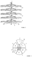
- Fig. 1 is a side view of a tray stand in accordance with the invention,
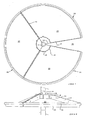
- Fig. 2 is a schematic illustration of a tray in the tray stand according to Fig. 1, seen from above,
- Fig. 3 is a schematic view similar to the one in Fig. 2, but to a larger scale and only illustrating the central portion of the tray,
- Fig. 4 is a schematic perspective view illustrating a tray section and its mounting on the holder for the tray in question, and
- Fig. 5 schematically illustrates a section through two adjacent tray sections,
- Fig. 6 is a side view of another embodiment of a tray stand in accordance with the invention,
- Fig. 7 is a plan view to a larger scale of a tray included in the tray stand of Fig. 6,
- Fig. 8 is a side view of the tray in Fig. 7,
- Fig. 9 and 10 are a plan view and side view respectively of the tray in Figs. 7 and 8, provided with loose partition walls,
- Fig. 11 is a section to an even larger scale through the vertical column of rotation shaft of the tray stand, on which a tray has been rotatably mounted.
- As will be seen from the drawing, especially Fig. 1, a tray stand in accordance with the invention includes a central, vertical column 1, which is normally carried by a base, a foot or the like 2. The central column 1 carries a plurality of circular trays or
shelves 3 arranged one above the other, and which are individually rotatable round the column 1. - As will most clearly be seen from Figs. 2 and 3, each such circular tray comprises a plurality, in the illustrated embodiment six, substantially circle sector-
shaped sections 4, which are carried by acommon holder 5 rotatably mounted on the central column 1. Each of these circle sector-shaped tray sections 4 is individually withdrawable and retractable in a substantially radial direction relative theholder 5. In Fig. 2 there is shown one of the circle sector-shaped tray sections 4 in its withdrawn position, while the remainder are in their normal, entirely retracted positions. When atray section 4 is in its withdrawn position, the space on this section is easily accessible for refilling new goods on this section or for taking goods from it. - As will be seen from Figs. 2-4, the
holder 5 rotatably mounted on the central column 1 and common to a given tray, comprises to advantage acentral part 5a and a number ofarms 5b corresponding to the number oftray sections 4, these arms projecting out substantially radially from thecentral part 5a. Thearms 5b each carry one of the circle sector-shaped tray sections 4, to advantage in the way illustrated in Fig. 4, by eachsection 4 being provided with a sleeve-like part 6 which is telescopically placed over the associatedarm 5b on theholder 5. In this way, eachtray section 4 can be displaced in a substantially radial direction along the associatedarm 5b on theholder 5 between a normal, entirely retracted position and a withdrawn position. To advantage, eachtray section 4 is provided with a suitable, manually operable latching means, with the aid of which each tray section can be locked in its retracted or withdrawn position. - In order that the goods shall be easily accessible at the outer edge of the tray sections, without the sections needing to be withdrawn, the
arms 5b of therotatable holders 5 are to advantage arranged such that they are inclined downwards, e.g. at an angle of about 15° relative to the horizontal plane. Thetray sections 4 will thus also slope in the same way, whereby the goods kept on the tray sections will glide down towards the outer arcuate edge of the tray sections at the rate the goods are removed therefrom. - As is most clearly apparent from Fig. 4, each
tray section 4 can to advantage be formed as a low box with a substantially circle sector-shaped bottom 4a, having along its arcuate outer edge anarcuate wall 4b and along its radial side edges walls 4c and 4d. The bottom 4a does not need to extend right into the inner tip of the tray section, which may lack a bottom, as illustrated in Fig. 4. This makes the tray section lighter and facilitates manufacture of the bottom 4a. Since thetray sections 4 slope downwards and outwards relative the horizontal plane it is advantageous that the bottom 4a in each tray section is conically curved, so that the tray sections carried by one and thesame holder 5 and together forming a tray, extend along a conical surface with a vertex angle corresponding to the slope of the tray sections relative the horizontal plane. There is thus achieved that the spacing in height between two trays lying one above the other is everywhere just as great, which is advantageous with respect to the height of the goods placed on the tray sections. At its outer or forward edge, thetray section 4 can be provided with a handle 7, which is used for withdrawing and retracting the individual tray sections and also for rotating an entire tray round the column 1. Furthermore, eachsection 4 can be provided at its inner, narrower end with awire 8, or some other suitable element preventing goods from falling down through the opening 9 where the tray sections have no bottom 4a. If so desired, the space on a tray section can be divided up into several compartments with the aid of suitably formed partition walls, not illustrated on the drawing, which are attached to thewire 8 and thefront wall 4b of the tray sections. - By the
arms 5b on theholder 5 being formed with a suitable cross section, e.g. rectangular as in the illustrated embodiment, and the telescope sleeves 6 on thetray sections 4 being formed with a corresponding cross section, it is achieved that thetray sections 4 will be non-rotatable about thearms 5b. Further improved stability may be achieved by the radial side walls 4c, 4d of thetray sections 4 being formed with elements engaging each other in the mutually adjacent tray sections in the same tray, when the tray sections are in a retracted position, and which prevent mutual movement between adjacent tray sections in a direction at right angles towards the plane of the tray section and which thereby achieves a mutual stabilization of associated tray sections. This can be achieved in a very simple and advantageous way by the radial side walls 4c and 4d of thetray sections 4 being formed with cross section configurations engaging with, and complemental to each other, as is schematically illustrated in Fig. 5, which is a section through the mutually adjacent side walls 4c and 4d of two mutually adjacent tray sections. These profiles can advantageously be provided with a cushioning material on their coacting surfaces. - The alternative embodiment of a tray stand according to the invention illustrated in Fig. 6 includes a
foot 10, avertical column 12 carried by thefoot 10, the construction of the column being described in detail below, there being a plurality oftrays 14 mounted on thecolumn 12, such as to be mutually independently rotatable. - Each
tray 14 is circular, and, as illustrated in Figs. 7 and 8 in the illustrated embodiment, includes ahub 16, from which depart a plurality of arms orspokes 18, in this particular case fourarms 18, which divide the circle into four sectors. Three of these circle sectors are equally as great and in these there are arranged circle sector-shaped tray sections 20 comprising abottom surface 22 andside walls 24, as well as an inner 26 and an outer 28 peripheral wall, the inner wall being provided with substantially vertically extendingdepressions 30 serving as reinforcing, and possible fixings for loose partition walls, as described in detail below. The outerperipheral wall 28 is provided with aflange 32 for reinforcing its edge. The threetray sections 20 are arranged between thearms 18 and attached to them with suitable fastening means, such as screws orrivets 34. In accordance with the invention these three circle sector-shaped tray sections 20 form together a circle sector having an extension less than 360° of the circle, thus to form a fourthlesser sector 36 in which no tray section is arranged, thissector 36 forming an opening in the tray (see also Fig. 6). Theopening 36 is given a size such that articles and objects in the case of use in question, which are to be stored in the trays, can be comfortably placed via theopening 36 at least on the underlying tray, also furthest in on it towards theinner wall 26. - By rotating the underlying and/or the overlying tray, the entire storage surface in the underlying tray will be accessible for refilling and possible removal of articles.
- Of course, the number of
arms 18 and thereby the number oftray sections 20, as well as the size of them, may be varied to meet requirements placed by the user of the tray stand. Another way of changing the division of the trays is shown in Figs. 9 and 10, in which the parts of the trays which are the same as in Figs. 7 and 8 have been given the same reference denotations. One or more of thetray sections 20 is here divided into different compartments with the aid ofloose partition walls 38 in a desired manner, in the illustrated case two long, narrow rectangular compartments and two that are larger and circle sector-shaped. As is also apparent from Fig. 6, thepartition walls 38 are upwardly formed with atip 40, gripping over the outerperipheral wall 28 of thesection 20, and downwards with a hook-shaped foot 42 engaging in a trough-like opening 44 extending downwards along the outer peripheral edge of eachtray section 20. At the end of thepartition wall 38 facing towards the centre of thecircular tray 14 there is arranged ahook 46 gripping over the edge of the innerperipheral wall 26, preferably in one of thedepressions 30 in thewall 26. - As previously mentioned, the
trays 14 are mounted rotatably on avertical column 12 extending along the entire height of the tray stand. As illustrated in Fig. 11, the column includesseveral sections 48 which are identically alike, and provided with a threadedstub 50 adapted for screwing into a mating thread in anunderlying section 48. A desired number ofsuch sections 48 are screwed together in this way to form a tray stand of the desired height. Thelowest section 48 in thecolumn 12 is threaded into a mating thread in thefoot 10 as illustrated in Fig. 6. - A
washer 52 is clamped between the screwed-togethersections 48 at each joint, to form a race for a number ofballs 54 arranged in a groove in the lower face of eachshelf hub 16. These balls form, together with the washer, a rolling bearing for facilitating rotation of thehub 16 round thestationary column 12. The length of eachsection 48 in thecolumn 12 is somewhat greater than the length of thetubular tray hubs 16, to make room for thewasher 52 and the necessary clearance between thehub 16 andwasher 52. The length of eachsection 48 will thus also define the desired distance between thetrays 14 in the assembled tray stand. - It will be apparent from the above description that in accordance with the invention there has been achieved a tray stand of very simple construction, with which the objects set forth in the introduction have been achieved. By arranging the
tray sections 4 withdrawable, as shown in the embodiment of Figs. 1 to 5, or forming anopening 36 such as thetray sections 22 in the embodiment of Figs. 6-11, there is obtained the possibility of easily filling and possibly removing articles on an underlying tray. The tray stand can be very rapidly built up to the desired height, due to the embodiment as shown in Fig. 11. - It should be understood that the illustrated and described embodiments are only examples of the realization of the invention, and that alterations and modifications can be made within the scope of the following claims.
Claims (8)
- A tray stand including a vertical column (1, 12) and a plurality of circular trays (3, 14) rotatably mounted one above the other on the column, each tray including a plurality of substantially circle sector-shaped tray sections (4, 22), which are carried by a common holder (5, 16) in such a way that together they form the circular tray (3, 14) and that the tray sections (4, 22) are arranged in the tray stand so that the whole surface of the section is accessible without obstruction by the overlying tray (3, 14), characterized in that the holder (5,16) includes a central hub rotatably mounted on the column (1, 12) and carrying the said tray sections (4, 29) so that the trays (3, 14) slope downwards in a direction from the column (1, 2) towards the outer periphery of the trays.
- A tray stand according to claim 1, characterized of the tray sections (4) being individually withdrawable and retractable in a substantially radial direction relative to the holder (5).
- Tray stand as claimed in claim 1, characterized of the tray sections (22) together forming less than 360o of the circular arc to form an opening (36) in the tray said opening (36) having a size such that articles or objects can be removed from, or placed on the tray (14), situated nearest below it.
- Tray stand as claimed in any of claims 1 - 3, characterized in that the tray sections (4, 22) have a conically curved shape corresponding to said slope.
- Tray stand as claimed in any of claims 1 - 4, characterized in that the hub has a number of arms (5b) corresponding to the number of tray sections (4) and projecting radially from the hub, each tray section (4) being displaceably carried by such an arm (5b).
- Tray stand as claimed in claim 5, characterized in that each tray section (4) is provided with a sleeve-like part (6) which is thrust over the associated arm (5b) of the holder (5), which arm (5b) preferably has a cross section, e.g. a rectangular cross section, which prevents rotation of the tray sections (4) about the longitudinal axes of the arm (5b).
- Tray stand as claimed in any of claims 1 - 6, characterized in that the hubs (5, 16) of the trays (3, 14) are mounted on a vertical column (1, 12), which is composed of several shaft-like sections (48), which are screwed one into each other, whereby the sections (48) have a length defining the distance between two trays (3, 14) and that at the joint between two sections there is arranged a bearing (54), on which the hub (5, 16) of the tray rests.
- Tray stand as claimed in any of claims 1 - 7, characterized in that the tray sections (4, 20) are box-shaped one or more of the walls of the box being provided with reinforcing means (4c, 4d, 30, 32) e.g. in the form of depressions, flanges or profiles.
Applications Claiming Priority (4)
| Application Number | Priority Date | Filing Date | Title |
|---|---|---|---|
| SE8503671 | 1985-08-01 | ||
| SE8503671A SE449293B (en) | 1985-08-01 | 1985-08-01 | HYLLSTELL |
| SE8601061 | 1986-03-07 | ||
| SE8601061A SE453717B (en) | 1986-03-07 | 1986-03-07 | Carousel-type tray stand |
Publications (3)
| Publication Number | Publication Date |
|---|---|
| EP0211816A2 EP0211816A2 (en) | 1987-02-25 |
| EP0211816A3 EP0211816A3 (en) | 1987-08-26 |
| EP0211816B1 true EP0211816B1 (en) | 1991-08-28 |
Family
ID=26659037
Family Applications (1)
| Application Number | Title | Priority Date | Filing Date |
|---|---|---|---|
| EP86850270A Expired - Lifetime EP0211816B1 (en) | 1985-08-01 | 1986-07-29 | Tray stand |
Country Status (8)
| Country | Link |
|---|---|
| US (1) | US4736856A (en) |
| EP (1) | EP0211816B1 (en) |
| CN (1) | CN1009153B (en) |
| DE (1) | DE3681096D1 (en) |
| DK (1) | DK162734C (en) |
| ES (1) | ES2001057A6 (en) |
| FI (1) | FI85800C (en) |
| NO (1) | NO164878C (en) |
Cited By (2)
| Publication number | Priority date | Publication date | Assignee | Title |
|---|---|---|---|---|
| US6196400B1 (en) | 1996-08-30 | 2001-03-06 | Sintek International Ab | Shelving stand |
| EP1679020A1 (en) | 2004-12-29 | 2006-07-12 | GEBR. WILLACH GmbH | Round shelf unit |
Families Citing this family (74)
| Publication number | Priority date | Publication date | Assignee | Title |
|---|---|---|---|---|
| USD302889S (en) | 1985-11-15 | 1989-08-15 | Goodwin Jeffrey M | Food serving cart |
| US4865283A (en) * | 1987-04-03 | 1989-09-12 | Parker Robert J | Merchandising display stand |
| US4964520A (en) * | 1989-08-07 | 1990-10-23 | International Packaging Corporation | Display assembly |
| FR2651653B1 (en) * | 1989-09-08 | 1994-06-03 | Blaize Jack | STORAGE CABINET FOR MANY SMALL OBJECTS. |
| USD322522S (en) | 1989-11-09 | 1991-12-24 | John Ferris | Combined storage and display rack for cut flowers |
| US5255801A (en) * | 1990-08-30 | 1993-10-26 | Rga Accessories, Inc. | Free-standing merchandise display |
| US5199580A (en) * | 1991-08-13 | 1993-04-06 | Bankier Companies, Inc. | Banana carrier |
| USD354869S (en) | 1992-11-27 | 1995-01-31 | Salyer David G | Stackable tray |
| USD361678S (en) | 1993-03-18 | 1995-08-29 | Displays By Garo, Inc. | Jewelry display stand |
| US5443166A (en) * | 1993-11-09 | 1995-08-22 | Schutte; John H. | Storage rack for use with a break press |
| AT19U3 (en) * | 1994-06-16 | 1995-02-27 | Transcom Stabilimento Transcom | STORAGE RACK |
| US5567026A (en) * | 1994-11-02 | 1996-10-22 | Master-Bilt | Apparatus for displaying products |
| US5715955A (en) * | 1995-12-14 | 1998-02-10 | Hannecke; Wolf-Dietrich | Merchandise presentation system of modular design |
| DE19701257A1 (en) | 1997-01-17 | 1998-07-23 | Hannecke Wolf D Kunststoff | Column presentation system in modular design for the display of goods or brochure material and in particular of thin objects |
| USD401810S (en) | 1997-03-21 | 1998-12-01 | Larry Swift | Display tray |
| USD402430S (en) | 1997-07-16 | 1998-12-08 | Dudley James M | Bird feeder |
| USD422443S (en) * | 1998-01-15 | 2000-04-11 | De Limur Eleanor | Swinging wall tray |
| US6016927A (en) * | 1998-01-30 | 2000-01-25 | Krupp; William A. | Rotating tray system |
| US6318566B1 (en) | 1999-04-02 | 2001-11-20 | L'oreal | System for displaying cosmetic products |
| USD451967S1 (en) | 2000-06-30 | 2001-12-11 | Bob Siemon Designs, Inc. | Stack of display rotators on a kiosk pole |
| USD449345S1 (en) | 2000-06-30 | 2001-10-16 | Bob Siemon Designs, Inc. | Display rotator for a kiosk |
| USD444964S1 (en) | 2000-06-30 | 2001-07-17 | Bob Siemon Designs, Inc. | Kiosk with stacks of display rotators |
| US6439406B1 (en) * | 2000-11-15 | 2002-08-27 | Mary Didier Duhon | Carousel device for storing medication containers |
| US6520352B2 (en) * | 2001-07-02 | 2003-02-18 | Anna L. Mondragon | Stackable lazy susan having central support column |
| US6502707B1 (en) * | 2001-08-31 | 2003-01-07 | Andrew Sullivan | Shoe carousel device |
| US6796443B2 (en) * | 2001-10-29 | 2004-09-28 | Plano Molding Company | Carousel |
| US20040055982A1 (en) * | 2002-06-21 | 2004-03-25 | Charles Jennings | Product display system |
| USD482213S1 (en) | 2002-12-05 | 2003-11-18 | Richard Cohon | Lampshade display |
| US20050076817A1 (en) * | 2003-04-04 | 2005-04-14 | Knape & Vogt Manufacturing Company | Lazy susan with pull-out shelving |
| JP4468051B2 (en) * | 2003-05-15 | 2010-05-26 | 有限会社 エー・ジー・ケー | Article suspension system, sliding wire fastener, removable wire fastener, wire hook and wire gripper |
| FR2862506A1 (en) * | 2003-11-26 | 2005-05-27 | Emmanuel Colombier | Flat document e.g. professional visiting card, displaying and distributing device, has cylindrical dispensers each comprising hole drilled at center and divided into sector for containing flat documents |
| US20050194873A1 (en) * | 2004-02-23 | 2005-09-08 | Hoffman Keith A. | Lazy susan device with tool free installation |
| US20070114191A1 (en) * | 2004-03-05 | 2007-05-24 | Shu-Lien Chen | Positioning rack for thin-type electrothermal straps |
| US20050268551A1 (en) * | 2004-06-08 | 2005-12-08 | Wen-Chi Lai | Self-watering breeding device |
| US20060032129A1 (en) * | 2004-06-08 | 2006-02-16 | Wen-Chi Lai | Self-watering breeding device |
| NZ534244A (en) * | 2004-07-20 | 2007-05-31 | Foodcap Int Ltd | Product distribution methods and apparatus |
| US8317052B2 (en) * | 2004-10-15 | 2012-11-27 | Foodcap International Limited | Container, lid and clip therefor |
| ES2530521T3 (en) * | 2004-10-15 | 2015-03-03 | Foodcap Int Ltd | Procedures and apparatus for thermal regulation of perishable products |
| EP1817738A4 (en) * | 2004-10-18 | 2011-01-05 | Foodcap Int Ltd | Processing, storage and distribution system for perishable food products |
| AU2005296386A1 (en) * | 2004-10-18 | 2006-04-27 | Foodcap International Limited | Methods and apparatus for processing perishable products |
| CA2626467A1 (en) * | 2004-10-18 | 2006-04-27 | Foodcap International Limited | Apparatus and methods for processing and distribution of perishable food products |
| AU2005244604B2 (en) * | 2004-12-29 | 2010-10-28 | Gebr. Willach Gmbh | Round-type shelf storage rack |
| US20070119806A1 (en) * | 2005-11-29 | 2007-05-31 | Le Sech Kirsten S | Cosmetic organizer |
| US8281939B2 (en) * | 2007-01-22 | 2012-10-09 | Shu-Lien Chen | Positioning rack for thin-type electrothermal straps |
| US20110073553A1 (en) * | 2008-06-05 | 2011-03-31 | Laura Davis Buege | Cosmetic organizer display |
| AU2010223861B2 (en) * | 2009-03-13 | 2015-11-26 | Adaius Pty Ltd | An improved storage carousel |
| USD611662S1 (en) * | 2009-04-15 | 2010-03-09 | Zenith Innovation, Llc | Bird feed tray |
| US20110079567A1 (en) * | 2009-10-01 | 2011-04-07 | Trena Anderson | Rotatable Shelf |
| USD623805S1 (en) * | 2009-12-29 | 2010-09-14 | Zenith Innovation, Llc | Modular bird feeder |
| USD638588S1 (en) * | 2010-12-28 | 2011-05-24 | Zenith Innovation, Llc | Hanging bird feeder |
| CN102273857B (en) * | 2011-05-03 | 2013-12-04 | 太仓市车中宝休闲用品有限公司 | Connecting pipe joint pressing assembling type multipurpose show shelf |
| US8777024B2 (en) | 2011-08-03 | 2014-07-15 | Teri Kramer | Portable organizer |
| US9022236B1 (en) * | 2012-02-20 | 2015-05-05 | Centricity Corporation | Rotary carousel apparatus and system |
| US20140263124A1 (en) * | 2013-03-18 | 2014-09-18 | Helen Of Troy Limited | Standing shower caddy |
| USD776462S1 (en) * | 2013-03-23 | 2017-01-17 | Michael Green | Pagoda soap tower |
| US10405651B1 (en) * | 2014-02-07 | 2019-09-10 | Teri Kramer | Portable paper organizer |
| CN105310369B (en) * | 2014-08-05 | 2019-09-20 | 福利佐之福利佐·保罗和C.有限公司 | The displaying device of sample for leather, fabric etc. |
| USD759408S1 (en) | 2015-04-08 | 2016-06-21 | Target Brands, Inc. | Display table |
| US9585476B2 (en) * | 2015-04-28 | 2017-03-07 | Joseph T. Swisher | Multifunction workstation |
| US10336504B2 (en) * | 2015-11-18 | 2019-07-02 | Ford Global Technologies, Llc | Storage device with infinitely adjustable storage divider system |
| USD765183S1 (en) * | 2015-11-20 | 2016-08-30 | Robert Lowery | Marble game |
| GB2564039A (en) * | 2016-03-16 | 2019-01-02 | Xiamen Toppla Mat Tech Co Ltd | Safe cylindrical combined cabinet for outdoor use |
| US10327389B1 (en) * | 2017-04-19 | 2019-06-25 | Jared Brownscombe | Hanging drying rack |
| CN107440408A (en) * | 2017-07-03 | 2017-12-08 | 合肥震岳工业设备科技有限公司 | Multi-functional storage rack |
| WO2019055917A1 (en) * | 2017-09-15 | 2019-03-21 | Six Continents, Inc. | Convertible breakfast station |
| US11147387B2 (en) | 2017-11-13 | 2021-10-19 | Edward Schneidewent | Under-bed storage unit |
| CN108814011B (en) * | 2018-04-24 | 2020-02-11 | 窦彩艳 | Working method of medicine carrying rack capable of automatically pushing and stacking boxed medicines |
| US10694844B1 (en) * | 2018-07-18 | 2020-06-30 | Ole Falk Smed | Wine carousel |
| CN110589178A (en) * | 2019-09-20 | 2019-12-20 | 山东劳动职业技术学院(山东劳动技师学院) | Logistics distribution frame convenient to goods are categorised |
| USD921401S1 (en) * | 2020-01-24 | 2021-06-08 | TAK Logic, Inc. | Organizing device |
| USD927903S1 (en) * | 2020-04-03 | 2021-08-17 | Bknest | Rotating display stand |
| CN113243708B (en) * | 2021-06-03 | 2023-02-28 | 深圳市小辉冷链科技有限公司 | Show type freezer |
| US20230286749A1 (en) * | 2022-03-14 | 2023-09-14 | Rightbot Technologies, Inc. | System and a method for handling inventory in a nano robotic fulfillment center or a robotic dark store |
| US20250215651A1 (en) * | 2022-07-19 | 2025-07-03 | Michael Paul Macropoulos | Traffic Barrel Safe Stacking System |
Family Cites Families (11)
| Publication number | Priority date | Publication date | Assignee | Title |
|---|---|---|---|---|
| US574380A (en) * | 1897-01-05 | Revolving show-case | ||
| US353419A (en) * | 1886-11-30 | Tool-receptacle | ||
| US727107A (en) * | 1903-01-12 | 1903-05-05 | Ellsworth E Donaldson | Revolving bin. |
| FR383186A (en) * | 1907-10-22 | 1908-02-26 | Joseph Gautier | Rotating locker |
| US922888A (en) * | 1908-04-16 | 1909-05-25 | Albert W Grunwaldt | Grain sprouting or germinating apparatus. |
| US1576802A (en) * | 1922-10-30 | 1926-03-16 | Dema Martin Alfrey | Cabinet |
| US2354835A (en) * | 1942-01-03 | 1944-08-01 | Rosenberg Philip | Cabinet |
| US2553507A (en) * | 1950-03-13 | 1951-05-15 | Universal Steel Equipment Corp | Locking mechanism for revolving bins |
| US3198338A (en) * | 1964-02-05 | 1965-08-03 | Rayna H Mccormick | Bowling ball display rack |
| US4036367A (en) * | 1976-10-14 | 1977-07-19 | Stambaugh Sherwood C | Rotatable shoe rack |
| IT8252859U1 (en) * | 1982-02-01 | 1983-08-01 | Ferrero Spa | MODULAR STRUCTURE DISPLAY UNIT, ESPECIALLY FOR DISPLAYING FOOD PRODUCTS PACKAGED IN TRAYS. |
-
1986
- 1986-07-15 FI FI862945A patent/FI85800C/en not_active IP Right Cessation
- 1986-07-25 DK DK355386A patent/DK162734C/en not_active IP Right Cessation
- 1986-07-29 DE DE8686850270T patent/DE3681096D1/en not_active Expired - Lifetime
- 1986-07-29 CN CN86105516A patent/CN1009153B/en not_active Expired
- 1986-07-29 EP EP86850270A patent/EP0211816B1/en not_active Expired - Lifetime
- 1986-07-30 US US06/890,529 patent/US4736856A/en not_active Expired - Fee Related
- 1986-07-31 NO NO863093A patent/NO164878C/en not_active IP Right Cessation
- 1986-07-31 ES ES8600786A patent/ES2001057A6/en not_active Expired
Cited By (3)
| Publication number | Priority date | Publication date | Assignee | Title |
|---|---|---|---|---|
| US6196400B1 (en) | 1996-08-30 | 2001-03-06 | Sintek International Ab | Shelving stand |
| US6328172B2 (en) | 1996-08-30 | 2001-12-11 | Sintek International Ab | Shelving stand |
| EP1679020A1 (en) | 2004-12-29 | 2006-07-12 | GEBR. WILLACH GmbH | Round shelf unit |
Also Published As
| Publication number | Publication date |
|---|---|
| DK355386A (en) | 1987-02-02 |
| NO863093D0 (en) | 1986-07-31 |
| EP0211816A2 (en) | 1987-02-25 |
| US4736856A (en) | 1988-04-12 |
| FI85800C (en) | 1992-06-10 |
| FI862945L (en) | 1987-02-02 |
| ES2001057A6 (en) | 1988-04-16 |
| FI85800B (en) | 1992-02-28 |
| NO164878C (en) | 1990-11-28 |
| NO863093L (en) | 1987-02-02 |
| NO164878B (en) | 1990-08-20 |
| FI862945A0 (en) | 1986-07-15 |
| DK355386D0 (en) | 1986-07-25 |
| CN86105516A (en) | 1987-02-04 |
| CN1009153B (en) | 1990-08-15 |
| DE3681096D1 (en) | 1991-10-02 |
| DK162734C (en) | 1992-04-27 |
| EP0211816A3 (en) | 1987-08-26 |
| DK162734B (en) | 1991-12-09 |
Similar Documents
| Publication | Publication Date | Title |
|---|---|---|
| US4736856A (en) | Tray stand | |
| US3538863A (en) | Rotatable display,storage and merchandise distribution cabinet | |
| EP0373127B1 (en) | Mobile plate stand | |
| US4480755A (en) | Tool storage device | |
| US6502707B1 (en) | Shoe carousel device | |
| US4305511A (en) | Utensil storage device | |
| US6460950B2 (en) | Modular container/bookshelf moving cart | |
| US2526246A (en) | Self-locking structure | |
| US3744866A (en) | Display and dispensing bin | |
| US3207095A (en) | Multi-purpose material handling structure | |
| CA1277141C (en) | Modular display and storage unit | |
| US20050076817A1 (en) | Lazy susan with pull-out shelving | |
| WO1999005937A2 (en) | Sliding and tilting shelf drawer | |
| US20150238032A1 (en) | Kitchen Utensil Organizer | |
| EP2405785B1 (en) | An improved storage carousel | |
| US2260294A (en) | Display rack | |
| US3164259A (en) | Parts container and mounting means therefor | |
| US4974734A (en) | Radially expandable shelf display | |
| US4909400A (en) | Rotating merchandising stand | |
| EP2078473A1 (en) | Assortment cabinet | |
| JPS6297512A (en) | Tray stand | |
| US3149729A (en) | Display rack | |
| US4802715A (en) | Device for the storage of objects in a plurality of containers | |
| US3094362A (en) | Rotary racks for kitchen cabinets and the like | |
| KR200187453Y1 (en) | Rotationable display stand |
Legal Events
| Date | Code | Title | Description |
|---|---|---|---|
| PUAI | Public reference made under article 153(3) epc to a published international application that has entered the european phase |
Free format text: ORIGINAL CODE: 0009012 |
|
| AK | Designated contracting states |
Kind code of ref document: A2 Designated state(s): BE CH DE FR GB LI NL |
|
| PUAL | Search report despatched |
Free format text: ORIGINAL CODE: 0009013 |
|
| AK | Designated contracting states |
Kind code of ref document: A3 Designated state(s): BE CH DE FR GB LI NL |
|
| 17P | Request for examination filed |
Effective date: 19880203 |
|
| 17Q | First examination report despatched |
Effective date: 19891228 |
|
| GRAA | (expected) grant |
Free format text: ORIGINAL CODE: 0009210 |
|
| RAP1 | Party data changed (applicant data changed or rights of an application transferred) |
Owner name: SINTEK AB |
|
| AK | Designated contracting states |
Kind code of ref document: B1 Designated state(s): BE CH DE FR GB LI NL |
|
| PG25 | Lapsed in a contracting state [announced via postgrant information from national office to epo] |
Ref country code: CH Effective date: 19910828 Ref country code: LI Effective date: 19910828 Ref country code: BE Effective date: 19910828 Ref country code: FR Effective date: 19910828 |
|
| REF | Corresponds to: |
Ref document number: 3681096 Country of ref document: DE Date of ref document: 19911002 |
|
| REG | Reference to a national code |
Ref country code: CH Ref legal event code: PL |
|
| EN | Fr: translation not filed | ||
| PLBE | No opposition filed within time limit |
Free format text: ORIGINAL CODE: 0009261 |
|
| STAA | Information on the status of an ep patent application or granted ep patent |
Free format text: STATUS: NO OPPOSITION FILED WITHIN TIME LIMIT |
|
| 26N | No opposition filed | ||
| REG | Reference to a national code |
Ref country code: GB Ref legal event code: IF02 |
|
| PGFP | Annual fee paid to national office [announced via postgrant information from national office to epo] |
Ref country code: GB Payment date: 20050711 Year of fee payment: 20 |
|
| PGFP | Annual fee paid to national office [announced via postgrant information from national office to epo] |
Ref country code: NL Payment date: 20050719 Year of fee payment: 20 |
|
| PGFP | Annual fee paid to national office [announced via postgrant information from national office to epo] |
Ref country code: DE Payment date: 20050720 Year of fee payment: 20 |
|
| PG25 | Lapsed in a contracting state [announced via postgrant information from national office to epo] |
Ref country code: GB Free format text: LAPSE BECAUSE OF EXPIRATION OF PROTECTION Effective date: 20060728 |
|
| PG25 | Lapsed in a contracting state [announced via postgrant information from national office to epo] |
Ref country code: NL Free format text: LAPSE BECAUSE OF EXPIRATION OF PROTECTION Effective date: 20060729 |
|
| REG | Reference to a national code |
Ref country code: GB Ref legal event code: PE20 |
|
| NLV7 | Nl: ceased due to reaching the maximum lifetime of a patent |
Effective date: 20060729 |