EP0211701A1 - Torsional-damping device, especially for an automotive vehicle clutch, at least part of the damping being realized by an elastomeric element - Google Patents
Torsional-damping device, especially for an automotive vehicle clutch, at least part of the damping being realized by an elastomeric element Download PDFInfo
- Publication number
- EP0211701A1 EP0211701A1 EP86401276A EP86401276A EP0211701A1 EP 0211701 A1 EP0211701 A1 EP 0211701A1 EP 86401276 A EP86401276 A EP 86401276A EP 86401276 A EP86401276 A EP 86401276A EP 0211701 A1 EP0211701 A1 EP 0211701A1
- Authority
- EP
- European Patent Office
- Prior art keywords
- hub
- elastic means
- washer
- rotation
- integral
- Prior art date
- Legal status (The legal status is an assumption and is not a legal conclusion. Google has not performed a legal analysis and makes no representation as to the accuracy of the status listed.)
- Granted
Links
Images


Classifications
-
- F—MECHANICAL ENGINEERING; LIGHTING; HEATING; WEAPONS; BLASTING
- F16—ENGINEERING ELEMENTS AND UNITS; GENERAL MEASURES FOR PRODUCING AND MAINTAINING EFFECTIVE FUNCTIONING OF MACHINES OR INSTALLATIONS; THERMAL INSULATION IN GENERAL
- F16D—COUPLINGS FOR TRANSMITTING ROTATION; CLUTCHES; BRAKES
- F16D13/00—Friction clutches
- F16D13/58—Details
- F16D13/60—Clutching elements
- F16D13/64—Clutch-plates; Clutch-lamellae
- F16D13/68—Attachments of plates or lamellae to their supports
- F16D13/686—Attachments of plates or lamellae to their supports with one or more intermediate members made of rubber or like material transmitting torque from the linings to the hub
-
- F—MECHANICAL ENGINEERING; LIGHTING; HEATING; WEAPONS; BLASTING
- F16—ENGINEERING ELEMENTS AND UNITS; GENERAL MEASURES FOR PRODUCING AND MAINTAINING EFFECTIVE FUNCTIONING OF MACHINES OR INSTALLATIONS; THERMAL INSULATION IN GENERAL
- F16F—SPRINGS; SHOCK-ABSORBERS; MEANS FOR DAMPING VIBRATION
- F16F15/00—Suppression of vibrations in systems; Means or arrangements for avoiding or reducing out-of-balance forces, e.g. due to motion
- F16F15/10—Suppression of vibrations in rotating systems by making use of members moving with the system
- F16F15/12—Suppression of vibrations in rotating systems by making use of members moving with the system using elastic members or friction-damping members, e.g. between a rotating shaft and a gyratory mass mounted thereon
- F16F15/121—Suppression of vibrations in rotating systems by making use of members moving with the system using elastic members or friction-damping members, e.g. between a rotating shaft and a gyratory mass mounted thereon using springs as elastic members, e.g. metallic springs
- F16F15/124—Elastomeric springs
Definitions
- the present invention relates, in general, to torsion damping devices, in particular for clutches of motor vehicles, which comprise at least three coaxial elements, namely a driven hub, a hub plate driving the latter in rotation with play, and a drive assembly comprising a packing disk, these coaxial elements being mounted to rotate relative to each other against elastic means having at least two levels of stiffness, and for at least two sectors of limited determined angular deflections by angular strokes between meshing means.
- This drive means is, in many cases, constituted by at least one axial spacer, most often a spacer between the lining-carrying disk of which it is integral and a rotary element thus secured in rotation with the latter and is maintained axially at a determined distance.
- the two abutment means determining the circumferential angular displacement of each baluster, consist of the substantially radial edges of a notch formed in rotary elements, the hub veil for example, being axially interposed between the packing disc and said rotary element integral with this one.
- a second type of so-called secondary engagement means consists of the engagement of two concentric teeth means having a determined angular play .
- the displacement relative to the driven part that is to say the hub, takes place beyond these limits in a second phase against the main elastic means , of greater stiffness which, given their stiffness relative to that of the secondary elastic means, behave like a rigid block during the first phase.
- the advantage presented by a torsion damping device with two successive stages of stiffness is to allow greater progressiveness than that presented by a single stage of stiffness, that is to say using only one kind of elastic means.
- the elastic means are coil springs arranged circumferentially in windows provided for this purpose in the various rotary elements used.
- the springs have a linear function (displacement / force). This implies that the function determined by the behavior of such a device, expressed in terms of (angular travel / torque), has thresholds, determining linear operating ranges.
- the object of the present invention is a device torsion damper having a desirable progressiveness of operation without implying the above-mentioned drawbacks.
- a torsional damping device in particular for the clutch of a motor vehicle, of the type comprising at least three coaxial parts, a drive, an intermediate and a driven, rotatably mounted relative to each other within the limits of an angular displacement determined by means of engagement with clearance provided for this purpose between said coaxial parts, and against first and second elastic means with circumferential action, capable of acting circumferentially between them for two ranges at least angular deflections determined by means of engagement with clearance provided for this purpose between said coaxial parts, means for securing in rotation a first group of elements of the driving part, group comprising a friction disc and at at least one support and centering element thereof, with a guide washer one of the faces of which is integral in rotation with an annular element made of elas material tomer whose opposite radial face is integral in rotation with said intermediate coaxial part, characterized in that said annular elastomer element has an at least partially trapezoidal cross section inside, the small base of the trapezium
- the present invention also relates to a hub web assembly for a torsion damper in a motor vehicle clutch, characterized in that it comprises at least one annular elastomer element constituting a first elastic means with circumferential action and in that it meshes with play, to against a second elastic means with circumferential action, interposed between the hub web and said driven part which is a hub.
- such a hub web assembly is characterized in that it consists of at least two hub webs arranged coaxially at an axial distance from one another, said webs of hub being connected to each other by at least one annular elastomer element, in that a first hub wall is integral in rotation with the lining-carrier disc, and in that a second hub wall is integral in rotation with a concentric guide washer, the two hub webs meshing the hub 'by toothing means having different clearances.
- a hub plate assembly according to the invention comprises three separate hub plates between which two annular elastomer elements are interposed, the hub plate being in the intermediate position being a flat disc defining a plane of symmetry axial of said assembly and the three hub webs mesh the hub by toothing means having different clearances.
- said second elastic means are coil springs.
- said second elastic means are blocks of elastomeric material.
- said second elastic means and said first elastic means consist of a single annular elastomer element having axial projections near its internal diameter, said projections constituting said first elastic means.
- a particular advantage of the present invention over the prior art is the improvement in reliability hub sails. Indeed, these, in conventional torsional damping devices, are cut out of windows which necessarily weaken them.
- the annular elastomer element introduces non-linearity in the transmission of the torque, due to the internal losses specific to the material.
- the assembly of the device according to the invention bears the general reference 10 and comprises, as shown in FIGS. 1, 2, 3 and 4 a lining-carrying veil 11 integral in rotation and coaxial with a support flange 16, itself integral in rotation with a bearing 14 free to rotate around a hub 13 of which it surrounds one of the ends.
- the lining-carrying disc 11 constitutes a ring whose radially internal marginal zone is superimposed with a peripheral zone of the flange 16, thus establishing an annular radial contact surface.
- the three balusters, equidistant from a general axis 12 of the device according to the invention, are distributed at 120 * and pass through the flange and the lining carrier disc which they secure in forming a rivet.
- balusters 17, opposite the lining carrier disc also form a rivet, and secure a guide washer 18 and a so-called adhesion flange 19.
- the washer 18 and the flange 19 have a flat annular peripheral zone by which they are secured, with the heads of the balusters 17, which pass through them in this zone, extended by a tapered internal radial zone.
- the tapered internal radial zone of the flange 18 extends until it reaches a bearing 15, with which it is integral in rotation.
- the bearing 15 is free to rotate around the hub 13.
- the flange 19, radially less extended inwards than the washer 18, does not join the bearing 15.
- the washer 18 and the flange 19 are generally frustoconical, with the exception, however, of an axial recession 18 'and 19' respectively.
- recessions exactly overlap, extend in a plane normal to the axis of the balusters 17, and are located around the end of the latter.
- the role of such recessions is to provide a surface for fixing the heads of the balusters 17 normal to the axis of each of them, to allow riveting in good conditions.
- the guide washer 18 and the adhesion flange 19 fit together and are joined in rotation.
- the rotational connection of the bearing 15 and the washer 18 is effected by meshing three radial projections in the form of half-moons arranged 120 * from the bearing with three corresponding recesses provided for this purpose in the guide washer.
- a Belleville washer 20 rests on the guide washer 18 and exerts an axial pressure on the bearing 15 which it meshes with the same projections in half-moons.
- the cross section of the bearing 15 is generally L-shaped, the part axially located in mesh with the washer 18 having the smallest external diameter.
- the half-moon projections catch up with the largest external diameter of the bearing.
- the washer 14 meshes the flange 16 by three projections in half-moon in an identical manner.
- the bearings 14 and 15 are made of composite material.
- the washer 18 can be omitted, the flange 19 having in this case an axial flange while the bearing 15 is carried by a flange with an axial flange linked to the axial flange of the flange 19.
- annular element made of elastomeric material 22 is integral with the adhesion flange 19, on the one hand, and a hub plate 23 on the other hand.
- the annular element 22 follows by its two radial faces the adhesion flange 19 and the hub plate 23, to which it is secured by adhesion, a method known per se making it possible to secure a metallic element and a composite element, in elastomer, for example, during the vulcanization of the latter.
- the end of the flange 19 is situated on a circumference of diameter greater than the internal diameter, which facilitates the passage of a tool and makes it possible to vulcanize the element 22 on the hub veil and the flange without burr to form a subset.
- the hub cover 23 being a flat metal disc, the annular element 22 comprises a first peripheral zone delimited axially by the hub cover on the one hand, and by the planar peripheral area, parallel to the hub cover, of the flange grip 19, on the other hand.
- this first zone are formed three notches 24 extending over a radial height and a circumferential width allowing a circumferential movement of the balusters 17 in notches.
- the radial edges 25 of notches thus constitute stops which therefore limit the circumferential movement of these posts.
- the annular element 22 has, from the notches 24, axially projecting flanges which match and cover the edge of the edges of the notches 26 of the hub cover.
- the annular element 22 has a second concentric zone radially inside the first, of trapezoidal section, the small base of the trapezium being closest to the axis 12.
- the annular element 22 follows the shape of the washer 18 and the flange.
- This trapezoidal section is delimited by, on one side, the flat hub cover, and on the other side by the frustoconical part of the adhesion flange 19.
- the radial extent of the annular element 22 is identical to that of the flange 19 and its internal circumference of the element 22 is radially spaced from the hub plate 13 which it surrounds and more inside than that of said flange 19 .
- the annular element 22 is made of composite elastomer, of which a fibrous reinforcement is arranged circumferentially.
- the hub plate 23 is provided, at its internal circumference, with a toothing 27 which meshes with a corresponding toothing 28 of complementary configuration formed at the periphery of a radial projection 29 or flange of the hub 13, this gear comprising a determining circumferential clearance an angular clearance between the hub plate 23 and the hub 13.
- Denial windows 31.30 arranged circumferentially opposite in the radial projection 29 of the hub 13 and on the internal circumference of the hub web 23, constitute, when they are aligned, a window whose radial orientation edges draw the two halves with an X, the or each window thus formed housing a coil spring 32 disposed circumferentially and opposed, by compression of said spring 32 between an edge of the half-window 30 of the hub web 23 and an edge of the half window 31 of the hub 13, at any angular movement between the hub web and the hub.
- the lining carrier 11, the support flange 16, the columns 17, the guide washer 18, the adhesion flange 19 as well as the bearings 14 and 15 are therefore integral in rotation. Overall, all of these elements constitute a leading part.
- the hub cover 23 constitutes an intermediate part.
- the hub 13 constitutes a driven part.
- the annular elastomer element 22 integral by one of its radial faces with the driving part, transmits a torque, printed on this part by circumferential shear force, to the intermediate part, that is to say the web hub 23 of which it is integral by its other radial face.
- the element 22 therefore constitutes a first elastic means with circumferential action.
- This elastic means is opposed to the angular movement between the columns 17 of the driving part and the stops 25 of the notches 24 of the annular element 22 superimposed on the notches 26 of the hub web 23, the notches and the columns constituting means of meshing of the driving part with the intermediate part.
- the hub web 23 meshes with play on the hub 13, that is to say the driven part, an angular clearance between these two parts being against the springs 32.
- the springs 32 constitute a second elastic means with circumferential action of lower stiffness, in particular for good filtration of idle noise.
- a hub cover assembly comprises, in this embodiment, a guide washer 18, an adhesion flange 19, a first elastic means constituted by an annular element 22, a hub cover 23, and a second elastic means consisting of springs 32 arranged circumferentially and partially in half-windows 30 of the hub web.
- the hub web assembly as a whole, comprising at least two elastic means.
- the first elastic means offer a stiffness greater than that of the second elastic means by being arranged radially above the second means.
- the second elastic means compress until the teeth come into abutment meshing with the hub and the hub plate.
- the coupling in this case, becomes direct until the relative torque is weakened.
- Figures 5 and 6 show an alternative embodiment of the invention in which a support washer 33, provided with axial projections 34 substantially cylindrical on one of its faces, is pressed against the face of the remaining hub plate 23 free by an elastic washer 35, for example of the Belleville wavy washer type, the latter being supported on the flange 16.
- a support washer 33 provided with axial projections 34 substantially cylindrical on one of its faces, is pressed against the face of the remaining hub plate 23 free by an elastic washer 35, for example of the Belleville wavy washer type, the latter being supported on the flange 16.
- the protrusions 34 penetrate into orifices provided for this purpose in the flange 16 with sufficient clearance to allow relative axial movement between the support washer 33 and the flange 16 while securing them in rotation.
- the support washer 33 is made of composite material, and presses on a friction washer 36 integral in rotation with the hub 13.
- a hub wall assembly comprises two substantially identical hub walls 23 and 23 ′ arranged opposite one another and each having a zone peripheral in the form of a flat disc, a frustoconical intermediate zone, and an internal marginal zone in the form of a flat disc.
- An annular elastomer element 22 is interposed and adhered to the two opposite faces of the two hub webs which mesh with two different levels of play on a radial projection 29 of the hub 13.
- the hub cover 23 is secured by riveting to the flat carrier disc 11, directly mounted integral in rotation with the bearing 14, free to rotate around one end of the hub 13.
- the second hub wall 23 ' secured by riveting to a flat guide washer 18, which meshes with a bearing pushed axially by a Belleville washer resting on the guide washer 18 and by means of a washer d the support, as described above, is capable of abutting against the radial projection 29.
- the angular travel between the hub web 23 and the hub 13 is less than the angular travel between the hub web 23 'and the hub.
- Female teeth 30 (FIG. 9) formed in the hub cover 23 and larger female teeth 32 formed in the hub cover 23 ′ mesh with male teeth in the radial projection 29 of the hub.
- half-windows formed in the hub wall 23 and in the projection 29 of the hub are arranged opposite, so as to receive elastic means called second means.
- the two hub webs 23 and 23 ′ can be identical, the teeth 30 and 32 then being identical, while the male teeth of the radial projection 29 of the hub are different.
- these second elastic means consist of blocks known as "X" substantially parallelepiped, with lateral notches in obtuse angle, giving an aspect of X.
- these blocks X are in elaxromere.
- the elastomeric annular element 22 constitutes the first elastic means, of greater stiffness by its radial position and its radial extent, than the second elastic means.
- Figures 10 and 11 show another alternative embodiment comprising three different angular deflections, and three different levels of stiffness.
- the hub web assembly comprises three concentric hub webs 23, 23 ', 23 ", arranged axially separated by two elastomeric annular elements 22 and 22'.
- a first hub web 23 is integral with the lining carrier disc 11 and the support flange 16 having an axial offset towards the outside.
- This hub cover is adhered to a first elastomeric annular element 22, having, as in the first embodiment described, a peripheral part of rectangular cross section and an internal part of trapezoidal section.
- the first hub wall 23 is of a shape adapted to match a first radial face of this annular element 22.
- the second hub wall 23 ' is a flat disc disposed axially in the middle position to which the two flat faces of the elements 22 and 22' are adhered.
- the second elastomeric annular element 22 ′ is substantially identical to the first 22.
- the third hub plate 23 is symmetrical with respect to the plane of the second hub plate 23 'of the first hub plate 23, of which it also has the shape.
- the hub webs 23, 23 ′, 23 "all mesh with female teeth with male teeth of the radial projection 29 of the hub web, with three different angular deflections, going through Ascending .
- the elastomeric elements 22 and 22 ' after saturation of the first elastic means, tend to oppose the residual angular movement between the second hub web 23' and the hub. They thus constitute a second elastic means.
- Notches made in the first and second hub webs allow the passage of small columns 17 which join the lining carrier disc 11, the support flange 16 and the third hub web 23 ".
- FIG. 11 schematically represents the different angular deflections between the three hub webs 23, 23 ', 23 "and the radial projection of the hub 29, of which only one tooth 28 is shown.
- the circumferential travel of the balusters, between the radial edges of the notches forming a stop determines the possible angular travel between the successive hub webs.
- the supports of the hub web assembly thus formed around the hub are bearings 14 and 15, similar to those used in the embodiments described above.
- FIGS 12 and 13 show another alternative embodiment of the invention, in which a hub plate 23 called “main”, planar, is arranged opposite a hub plate 23 'said “secondary”, of form partially frustoconical, and partially planar, as described above in the other embodiments, these webs being separated by an annular elastomer element 22 adhered on its two faces to the two hub webs.
- the secondary hub cover 23 ′ is secured by means of three columns 17 of the lining carrier disc 11.
- the elastomeric annular element 22 has notches at its periphery, as well as the main hub web 23, notches allowing a circumferential deflection of the balusters 17, and the edges of which are covered with edges projecting axially from the element 22, similar to that set out in the description of the first variant of the invention.
- the main hub cover 23 meshes by toothing arranged at its internal circumference with a corresponding toothing of the hub, as described above.
- facing half-windows cooperate in order to form windows capable of receiving second elastic means.
- the second elastic means are X-shaped blocks constituted by axial projections 33 of the annular elastomer element 22, also and mainly forming the first elastic means.
- the first and second elastic means are provided by a single constituent element, namely the annular elastomer element 22, which is in this case provided with projections.
- this alternative embodiment of the invention which in particular allows, like the second alternative embodiment described, to obtain good progressiveness of the action of the two elastic means, both being made from elastomer elements, allows the use of conventional parts, namely conventional hub sheets.
- the invention is not limited, of course, to the variant embodiments described, but includes in particular any combination of the various particularities described, any extrapolation, in particular the multiplicity of elastic means, as well as any adaptation or improvement which would be deemed useful by the invention. skilled in the art.
Abstract
La présente invention concerne les dispositifs amortisseurs de torsion, notamment pour embrayage de véhicule automobile, du genre comportant au moins trois éléments coaxiaux rotatifs. Les trois éléments coaxiaux rotatifs, un moyen mené (13), un voile de moyeu (23), un disque porte garnitures (11), s'engrènent l'un l'autre avec deux niveaux de jeux différents à l'encontre de deux moyens élastiques (22, 32) à action circonférentielle présentant deux niveaux de raideurs différents. Au moins le moyen élastique (22) présentant la plus forte raideur est un élément annulaire en élastomère.The present invention relates to torsional damping devices, in particular for the clutch of a motor vehicle, of the type comprising at least three rotary coaxial elements. The three rotary coaxial elements, a driven means (13), a hub web (23), a lining carrier disc (11), mesh with each other with two different levels of play against two elastic means (22, 32) with circumferential action having two different levels of stiffness. At least the elastic means (22) having the greatest stiffness is an annular elastomer element.
Description
La présente invention concerne, d'une manière générale les dispositifs amortisseurs de torsion, notamment pour embrayages de véhicules automobiles, qui comportent au moins trois éléments coaxiaux, à savoir un moyeu mené, un voile de moyeu entraînant ce dernier en rotation avec jeu, et un ensemble d'entraînement comportant un disque porte-garnitures, ces éléments coaxiaux étant montés rotatifs les uns par rapport aux autres à l'encontre de moyens élastiques présentant au moins deux niveaux de raideur, et pour au moins deux secteurs de débattements angulaires déterminés limités par des courses angulaires entre des moyens d'engrènement.The present invention relates, in general, to torsion damping devices, in particular for clutches of motor vehicles, which comprise at least three coaxial elements, namely a driven hub, a hub plate driving the latter in rotation with play, and a drive assembly comprising a packing disk, these coaxial elements being mounted to rotate relative to each other against elastic means having at least two levels of stiffness, and for at least two sectors of limited determined angular deflections by angular strokes between meshing means.
Ces moyens d'engrènement sont, en pratique, de manière connue en soi, de deux genres :
- un premier genre de moyen d'engrènement dit principal, dont le débattement angulaire se fait à l'encontre de moyens élastiques dits principaux, présentant la plus forte raideur, est constitué d'au moins un moyen d'entraînement apte à se déplacer angulairement entre deux moyens de butée.
- a first type of so-called main engagement means, the angular displacement of which is against the so-called main elastic means, having the greatest stiffness, consists of at least one drive means capable of moving angularly between two stop means.
Ce moyen d'entraînement est, dans de nombreux cas, constitué d'au moins une entretoise axiale, le plus souvent une entretoise entre le disque porte-garnitures dont elle est solidaire et un élément rotatif ainsi solidarisé en rotation avec ce dernier et en est maintenu axialement à une distance déterminée.This drive means is, in many cases, constituted by at least one axial spacer, most often a spacer between the lining-carrying disk of which it is integral and a rotary element thus secured in rotation with the latter and is maintained axially at a determined distance.
De façon classique, également, les deux moyens de butée, déterminant le débattement angulaire circonférentiel de chaque colonnette, sont constitués par les bords sensiblement radiaux d'une échancrure ménagée dans des éléments rotatifs, le voile de moyeu par exemple, se trouvant axialement interposé entre le disque porte-garnitures et ledit élément rotatif solidaire de celui-ci.In a conventional manner, too, the two abutment means, determining the circumferential angular displacement of each baluster, consist of the substantially radial edges of a notch formed in rotary elements, the hub veil for example, being axially interposed between the packing disc and said rotary element integral with this one.
Un deuxième genre de moyen d'engrènement dit secondaire, dont le débattement angulaire se fait à l'encontre de moyens élastiques dits secondaires, présentant la plus faible raideur, est constitué de l'engagement de deux moyens de dentures concentriques présentant un jeu angulaire déterminé.A second type of so-called secondary engagement means, the angular displacement of which is made against so-called secondary elastic means, having the lowest stiffness, consists of the engagement of two concentric teeth means having a determined angular play .
Ainsi, lorsqu'un couple de torsion est appliqué à partir de la partie menante, celle-ci dans une première phase se déplace relativement à la partie menée en rotation à l'encontre des moyens élastiques secondaires, de plus faible raideur, jusqu'à ce que les limites de débattement angulaire du moyen d'engrènement secondaire soient atteintes.Thus, when a torque is applied from the driving part, this in a first phase moves relatively to the part driven in rotation against the secondary elastic means, of lower stiffness, up to that the angular displacement limits of the secondary engagement means are reached.
Si le couple de torsion est tel que ces limites soient atteintes, le déplacement relatif à la partie menée, c'est-à-dire le moyeu, se fait au delà de ces limites dans une deuxième phase à l'encontre des moyens élastiques principaux, de raideur supérieure qui, vu leur raideur par rapport à celle des moyens élastiques secondaires, se comportent comme un bloc rigide durant la première phase.If the torque is such that these limits are reached, the displacement relative to the driven part, that is to say the hub, takes place beyond these limits in a second phase against the main elastic means , of greater stiffness which, given their stiffness relative to that of the secondary elastic means, behave like a rigid block during the first phase.
Si les limites de débattement angulaire du moyen d'engrènement principal sont atteintes, le couplage entre parties menantes et parties menées est total.If the angular displacement limits of the main engagement means are reached, the coupling between driving parts and driven parts is complete.
Ce débattement angulaire entre le disque porte-garnitures et le moyeu se fait donc successivement à l'encontre de deux étages de moyens élastiques de raideurs différentes et de moyens de frottement. Ceci permet, de manière connue, de filtrer les vibrations notamment quand le véhicule est au "point mort". En pratique les moyens élastiques secondaires sont disposés sur une circonférence de plus petit diamètre que les ressorts principaux.This angular movement between the lining carrier disc and the hub therefore occurs successively against two stages of elastic means of different stiffness and friction means. This makes it possible, in known manner, to filter vibrations, in particular when the vehicle is in "neutral". In practice, the secondary elastic means are arranged on a circumference of smaller diameter than the main springs.
L'avantage présenté par un dispositif amortisseur de torsion à deux étages successifs de raideur est de permettre une plus grande progressivité que celle présentée par un seul étage de raideur, c'est-à-dire utilisant un seul genre de moyens élastiques.The advantage presented by a torsion damping device with two successive stages of stiffness is to allow greater progressiveness than that presented by a single stage of stiffness, that is to say using only one kind of elastic means.
En effet, traditionnellement, les moyens élastiques sont des ressorts à boudin disposés circonférentiellement dans des fenêtres ménagées à cet effet dans les différents éléments rotatifs mis en oeuvre.Indeed, traditionally, the elastic means are coil springs arranged circumferentially in windows provided for this purpose in the various rotary elements used.
Or, les ressorts présentent une fonction (déplacement/force) linéaire. Ceci implique que la fonction déterminée par le comportement d'un tel dispositif, s'exprimant en termes de (débattement angulaire/couple), présente des seuils, déterminant des plages de fonctionnement linéaires.However, the springs have a linear function (displacement / force). This implies that the function determined by the behavior of such a device, expressed in terms of (angular travel / torque), has thresholds, determining linear operating ranges.
Dans la pratique, cela se traduit par un manque de progressivité de l'accouplement des différentes pièces en rotation.In practice, this results in a lack of progressiveness in the coupling of the different rotating parts.
Outre les désagréments d'usage impliqués, l'usure des pièces s'en trouve accélérée.In addition to the inconvenience of use involved, the wear of the parts is accelerated.
Pour remédier au problème du manque de progressivité de fonctionnement des dispositifs amortisseurs de torsion à un seul étage de raideur, des dispositifs plus complexes à deux étages de raideur, et de débattements correspondants, dont la structure et le fonctionnement ont été succinctement décrits ci-dessus, ou même plusieurs étages de raideur, ont été développés.To remedy the problem of the lack of progressive operation of torsional damping devices with a single stiffness stage, more complex devices with two stiffness stages, and corresponding deflections, the structure and operation of which have been succinctly described above. , or even several stages of stiffness, have been developed.
On_comprendra que, bien évidemment, la multiplication des étages de raideur et de débattements, améliore la progressivité de fonctionnement du dispositif.On_comprendra that, obviously, the multiplication of stiffness stages and deflections, improves the progressiveness of the device.
Cependant, une telle multiplication présente plusieurs inconvénients :
- - D'une part, la relative complexité de construction, et par là même le coût, s'en trouvent accrus.
- - D'autre part, l'encombrement axial du dispositif tend à s'accroître, afin de permettre le logement des différents moyens élastiques.
- - On the one hand, the relative complexity of construction, and thereby the cost, are increased.
- - On the other hand, the axial size of the device tends to increase, in order to allow the accommodation of the various elastic means.
De plus, le logement des moyens élastiques dans des fenêtres découpées dans les éléments rotatifs tend à affaiblir ceux-ci. En pratique, ceci détermine des limites impératives à la multiplication des étages de raideur.In addition, the accommodation of the elastic means in windows cut out of the rotary elements tends to weaken them. In practice, this determines imperative limits to the multiplication of the stiffness stages.
L'objet de la présente invention est un dispositif amortisseur de torsion présentant une progressivité de fonctionnement souhaitable sans impliquer les inconvénients ci-dessus mentionnés.The object of the present invention is a device torsion damper having a desirable progressiveness of operation without implying the above-mentioned drawbacks.
A cette fin, un dispositif amortisseur de torsion selon l'invention, notamment pour embrayage de véhicule automobile, du genre comportant au moins trois parties coaxiales, une menante, une intermédiaire et une menée, montées rotatives l'une par rapport à l'autre dans les limites d'un débattement angulaire déterminé par des moyens d'engrènement à jeu prévus à cet effet entre lesdites parties coaxiales, et à l'encontre de premiers et seconds moyens élastiques à action circonférentielle, aptes à agir circonférentiellement entre elles pour deux plages au moins de débattements angulaires déterminées par des moyens d'engrènement à jeu prévus à cet effet entre lesdites parties coaxiales, des moyens de solidarisation en rotation d'un premier groupe d'éléments de la partie menante, groupe comportant un disque de friction et au moins un élément de support et de centrage de celui-ci, avec une rondelle de guidage dont l'une des faces est solidaire en rotation d'un élément annulaire en matière élastomère dont une face radiale opposée est solidaire en rotation avec ladite partie coaxiale intermédiaire, caractérisé en ce que ledit élément annulaire en élastomère présente une section transversale au moins partiellement trapézoidale à l'intérieur, la petite base du trapèze étant radialement la plus proche de l'axe du dispositif, et comporte au moins une partie métallique annulaire solidaire en rotation constituant l'une de ses faces radiales, ledit élément annulaire constituant au moins partiellement ledit premier moyen élastique à action circonférentielle.To this end, a torsional damping device according to the invention, in particular for the clutch of a motor vehicle, of the type comprising at least three coaxial parts, a drive, an intermediate and a driven, rotatably mounted relative to each other within the limits of an angular displacement determined by means of engagement with clearance provided for this purpose between said coaxial parts, and against first and second elastic means with circumferential action, capable of acting circumferentially between them for two ranges at least angular deflections determined by means of engagement with clearance provided for this purpose between said coaxial parts, means for securing in rotation a first group of elements of the driving part, group comprising a friction disc and at at least one support and centering element thereof, with a guide washer one of the faces of which is integral in rotation with an annular element made of elas material tomer whose opposite radial face is integral in rotation with said intermediate coaxial part, characterized in that said annular elastomer element has an at least partially trapezoidal cross section inside, the small base of the trapezium being radially closest to the 'axis of the device, and comprises at least one annular metal part integral in rotation constituting one of its radial faces, said annular element constituting at least partially said first elastic means with circumferential action.
La présente invention concerne également un ensemble voile de moyeu pour un amortisseur de torsion dans un embrayage de véhicule automobile, caractérisé en ce qu'il comporte au moins un élément annulaire en élastomère constituant un premier moyen élastique à action circonférentielle et en ce qu'il engrène avec jeu, à l'encontre d'un second moyen élastique à action circonférentielle, interposé entre le voile de moyeu et ladite partie menée qui est un moyeu.The present invention also relates to a hub web assembly for a torsion damper in a motor vehicle clutch, characterized in that it comprises at least one annular elastomer element constituting a first elastic means with circumferential action and in that it meshes with play, to against a second elastic means with circumferential action, interposed between the hub web and said driven part which is a hub.
Selon un mode de réalisation de l'invention, un tel ensemble voile de moyeu est caractérisé en ce qu'il est constitué d'au moins deux voiles de moyeu disposés coaxialement à distance axiale l'un par rapport à l'autre, lesdits voiles de moyeu étant reliés entre eux par au moins un élément annulaire en élastomère, en ce qu'un premier voile de moyeu est solidaire en rotation du disque porte-garnitures, et en ce qu'un second voile de moyeu est solidaire en rotation d'une rondelle de guidage concentrique, les deux voiles de moyeu engrenant le moyeu 'par des moyens de denture présentant des jeux différents.According to one embodiment of the invention, such a hub web assembly is characterized in that it consists of at least two hub webs arranged coaxially at an axial distance from one another, said webs of hub being connected to each other by at least one annular elastomer element, in that a first hub wall is integral in rotation with the lining-carrier disc, and in that a second hub wall is integral in rotation with a concentric guide washer, the two hub webs meshing the hub 'by toothing means having different clearances.
Selon un autre mode de réalisation, un ensemble voile de moyeu selon l'invention comporte trois voiles de moyeu séparés entre lesquels sont interposés deux éléments annulaires en élastomère, le voile de moyeu se trouvant en position intermédiaire étant un disque plat définissant un plan de symétrie axiale dudit ensemble et les trois voiles de moyeu engrènent le moyeu par des moyens de denture présentant des jeux différents.According to another embodiment, a hub plate assembly according to the invention comprises three separate hub plates between which two annular elastomer elements are interposed, the hub plate being in the intermediate position being a flat disc defining a plane of symmetry axial of said assembly and the three hub webs mesh the hub by toothing means having different clearances.
Selon un mode de réalisation de l'invention, et selon un de ses autres aspects, lesdits seconds moyens élastiques sont des ressorts à boudin.According to one embodiment of the invention, and according to one of its other aspects, said second elastic means are coil springs.
Selon un autre mode de réalisation de l'invention, lesdits seconds moyens élastiques sont des blocs en matériau élastomère.According to another embodiment of the invention, said second elastic means are blocks of elastomeric material.
Selon un mode particulièrement avantageux de réalisation de l'invention, lesdits seconds moyens élastiques et lesdits premiers moyens élastiques sont constitués d'un seul élément annulaire en élastomère présentant des saillies axiales à proximité de son diamètre interne lesdites saillies constituant lesdits premiers moyens élastiques.According to a particularly advantageous embodiment of the invention, said second elastic means and said first elastic means consist of a single annular elastomer element having axial projections near its internal diameter, said projections constituting said first elastic means.
Un avantage particulier de la présente invention par rapport à l'art antérieur est l'amélioration de la fiabilité des voiles de moyeu. En effet, ceux-ci, dans les dispositifs amortisseurs de torsion classiques, sont découpés de fenêtres qui les affaiblissent nécessairement.A particular advantage of the present invention over the prior art is the improvement in reliability hub sails. Indeed, these, in conventional torsional damping devices, are cut out of windows which necessarily weaken them.
De plus, travaillant en cisaillement entre ses deux faces radiales, l'élément annulaire en élastomère introduit une non-linéarité dans la transmission du couple, du fait des pertes internes propres au matériau.In addition, working in shear between its two radial faces, the annular elastomer element introduces non-linearity in the transmission of the torque, due to the internal losses specific to the material.
Une telle non-linéarité constitue, de fait, un amortissement tout à fait souhaitable de cette transmission.Such non-linearity constitutes, in fact, quite desirable damping of this transmission.
Les caractéristiques et avantages de l'invention ressortiront d'ailleurs de la description qui va suivre, à titre d'exemple, en référence aux dessins annexés dans lesquels :The characteristics and advantages of the invention will become apparent from the description which follows, by way of example, with reference to the accompanying drawings in which:
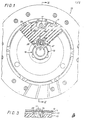
- la figure 1 est une vue en élévation, partiellement arrachée, d'un dispositif selon l'invention;Figure 1 is an elevational view, partially broken away, of a device according to the invention;
- la figure 2 est une vue en coupe selon II-II du même dispositif représenté par la figure 1 ;Figure 2 is a sectional view along II-II of the same device shown in Figure 1;
- la figure 2A est une vue correspondant à la figure 2 d'une variante d'exécution de l'invention ;Figure 2A is a view corresponding to Figure 2 of an alternative embodiment of the invention;
- la figure 3 est une vue de détail en coupe selon III-III du même dispositif ;Figure 3 is a detail view in section on III-III of the same device;
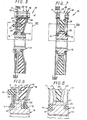
- la figure 4 est une vue de détail d'une partie IV de la figure 2 ;Figure 4 is a detail view of part IV of Figure 2;
- la figure 4A correspond à la figure 4, selon une autre variante d'exécution de l'invention ;FIG. 4A corresponds to FIG. 4, according to another alternative embodiment of the invention;
- la figure 5 est une vue en coupe d'une variante d'exécution de l'invention ;Figure 5 is a sectional view of an alternative embodiment of the invention;
- la figure 6 est une vue de détail de la partie VI de la figure 5 ;Figure 6 is a detail view of Part VI of Figure 5;
- la figure 7 est une vue en coupe d'une variante d'exécution de l'invention ;Figure 7 is a sectional view of an alternative embodiment of the invention;
- la figure 8 est une vue de détail de la partie VIII de la figure 7 ;Figure 8 is a detail view of Part VIII of Figure 7;
- la figure 9 est une vue schématique partielle en élévation plane de la variante d'exécution de l'invention représentée aux figures 7 et 8 ;Figure 9 is a partial schematic view in plan elevation of the alternative embodiment of the invention shown in Figures 7 and 8;
- la figure 10 est une vue en coupe d'une autre variante d'exécution de l'invention ;Figure 10 is a sectional view of another variant of the invention;
- la figure 11 est une représentation symbolique mettant en évidence le fonctionnement de la variante d'exécution de l'invention représentée à la figure 10 ;Figure 11 is a symbolic representation showing the operation of the alternative embodiment of the invention shown in Figure 10;
- la figure 12 est une vue en coupe d'une autre variante d'exécution de l'invention ;Figure 12 is a sectional view of another alternative embodiment of the invention;
- la figure 13 est une vue en élévation plane partiellement arrachée de la variante d'exécution de l'invention représentée à la figure 12.FIG. 13 is a plan view, partially cut away, of the variant embodiment of the invention shown in FIG. 12.
L'ensemble du dispositif selon l'invention porte la référence générale 10 et comporte, comme le représentent les figures 1,2,3 et 4 un voile porte-garnitures 11 solidaire en rotation et coaxial avec un flasque de support 16, lui-même solidaire en rotation d'un palier 14 libre en rotation autour d'un moyeu 13 dont il entoure l'une des extrémités.The assembly of the device according to the invention bears the
Trois entretoises, ici des colonnettes 17, dont les extrémités forment têtes de rivets, s'étendent axialement en saillie du disque porte-garnitures 11 qu'elles solidarisent avec le flasque 16.Three spacers, here
Plus précisément, le disque porte-garnitures 11 constitue un anneau dont la zone marginale radialement interne se superpose avec une zone périphérique du flasque 16, établissant ainsi une surface de contact radiale annulaire. Les trois colonnettes, équidistantes par rapport à un axe général 12 du dispositif selon l'invention, sont réparties à 120* et traversent le flasque et le disque porte-garnitures qu'elles solidarisent en formant rivet.More specifically, the lining-carrying
Les autres extrémités des colonnettes 17, à l'opposé du disque porte-garnitures, forment également rivet, et solidarisent une rondelle de guidage 18 et un flasque dit d'adhérence 19.The other ends of the
La rondelle 18 et le flasque 19 présentent une zone périphérique annulaire plate par laquelle ils sont solidarisés, avec les têtes des colonnettes 17, qui les traversent en cette zone,-prolongée par une zone radiale interne tronconique.The
La zone radiale interne tronconique du flasque 18 s'étend jusqu'à rejoindre un palier 15, avec lequel elle est solidaire en rotation. Le palier 15 est libre en rotation autour du moyeu 13. Le flasque 19, radialement moins étendu vers l'intérieur que la rondelle 18, ne rejoint pas le palier 15.The tapered internal radial zone of the
Selon une variante d'exécution représentée à la figure 2A la rondelle 18 et le flasque 19 sont globalement tronconiques, à l'exception cependant d'une récession axiale 18' et 19' respectivement. Ces récessions se superposent exactement, s'étendent dans un plan normal à l'axe des colonnettes 17, et sont localisées autour de l'extrémité de ces dernières. De telles récessions ont pour rôle d'offrir une surface de fixation des têtes des colonnettes 17 normale à l'axe de chacune de celles-ci, pour permettre un rivetage dans de bonnes conditions.According to an alternative embodiment shown in FIG. 2A, the
La rondelle de guidage 18 et le flasque d'adhérence 19 s'épousent et sont solidarisés en rotation.The
Comme le représente plus particulièrement la figure 4, la liaison en rotation du palier 15 et de la rondelle 18 s'effectue par engrènement de trois saillies radiales en forme de demi-lunes disposées à 120* du palier avec trois évidements correspondants ménagés à cet effet dans la rondelle de guidage. Une rondelle Belleville 20 s'appuie sur la rondelle de guidage 18 et exerce une pression axiale sur le palier 15 qu'elle engrène par les mêmes saillies en demi-lunes.As shown more particularly in Figure 4, the rotational connection of the
La section transversale du palier 15 est globalement en L, la partie axialement située en engrènement avec la rondelle 18 présentant le plus petit diamètre externe. Les saillies en demi-lunes rattrapent le diamètre externe le plus grand du palier.The cross section of the
Comme le montre la figure 4, la rondelle 14 engrène le flasque 16 par trois saillies en demi-lunes de façon identique.As shown in Figure 4, the
Avantageusement, les paliers 14 et 15 sont réalisés en matériau composite.Advantageously, the
En variante, comme représenté figure 4A, la rondelle 18 peut être supprimée, le flasque 19 possédant dans ce cas un rebord axial tandis que le palier 15 est porté par un flasque avec un rebord axial lié au rebord axial du flasque 19.As a variant, as shown in FIG. 4A, the
Dans tous les modes de réalisation, un élément annulaire en matière élastomère 22 est solidaire avec le flasque d'adhérence 19, d'une part, et un voile de moyeu 23 d'autre part.In all the embodiments, an annular element made of
Plus précisément, l'élément annulaire 22 épouse par ses deux faces radiales le flasque d'adhérence 19 et le voile de moyeu 23, auxquels il est solidarisé par adhérisation, procédé connu en soi permettant de solidariser un élément métallique et un élément composite, en élastomère, par exemple, pendant la vulcanisation de ce dernier.More specifically, the
On appréciera que l'extrémité du flasque 19 est située sur une circonférence de diamètre supérieur au diamètre interne ce qui facilite le passage d'un outil et permet de réaliser une vulcanisation de l'élément 22 sur le voile de moyeu et le flasque sans bavure pour former un sous-ensemble. Le voile de moyeu 23 étant un disque métallique plat, l'élément annulaire 22 comporte une première zone périphérique délimitée axialement par le voile de moyeu d'une part, et par la zone périphérique plane, parallèle au voile de moyeu, du flasque d'adhérence 19, d'autre part.It will be appreciated that the end of the
Dans cette première zone sont ménagées trois échancrures 24 s'étendant sur une hauteur radiale et une largeur circonférentielle permettant un débattement circonférentiel des colonnettes 17 dans des échancrures.In this first zone are formed three
Les bords radiaux 25 de échancrures constituent ainsi des butées qui limitent donc le débattement circonférentiel de ces colonnettes.The radial edges 25 of notches thus constitute stops which therefore limit the circumferential movement of these posts.
Trois échancrures 26 ménagées dans le voile de moyeu se superposent sensiblement aux échancrures 24, mais sont plus grandes circonférentiellement que celles-ci, de manière à ce que les colonnettes 17 viennent d'abord buter contre les échancrures 24 de l'élément annulaire 22. L'élément annulaire 22 présente, à partir des échancrures 24, des rebords axialement en saillie qui épousent et recouvrent la tranche des bords des échancrures 26 du voile de moyeu.Three
Ces rebords en saillie s'étendent axialement sensiblement sur toute l'épaisseur du voile de moyeu 23.These projecting flanges extend substantially axially over the entire thickness of the
On notera que l'on peut utiliser ainsi un moyeu classique et un voile de moyeu du type standard sans fenêtres.It will be noted that it is thus possible to use a conventional hub and a hub veil of the standard type without windows.
L'élément annulaire 22 présente une deuxième zone concentrique radialement à l'intérieur de la première, de section trapézoïdale, la petite base du trapèze étant la plus proche de l'axe 12.The
Bien entendu, selon la variante d'exécution représentée figure 2A dans laquelle la rondelle 18 et le flasque 19 sont tronconiques avec localement des zones parallèles, l'élément annulaire 22 épouse la forme de la rondelle 18 et du flasque.Of course, according to the variant shown in FIG. 2A in which the
Cette section trapézoïdale est délimitée par, d'un côté, le voile de moyeu plan, et de l'autre côté par la partie tronconique du flasque d'adhérence 19.This trapezoidal section is delimited by, on one side, the flat hub cover, and on the other side by the frustoconical part of the
L'étendue radiale de l'élément annulaire 22 est identique à celle du flasque 19 et sa circonférence interne de l'élément 22 se trouve radialement espacée du voile de moyeu 13 qu'il entoure et plus à l'intérieur que celle dudit flasque 19.The radial extent of the
Avantageusement, l'élément annulaire 22 est réalisé en élastomère composite, dont une armature fibreuse est disposée circonférentiellement.Advantageously, the
Le voile de moyeu 23 est muni, à sa circonférence interne, d'une denture 27 qui engrène une denture 28 correspondante de configuration complémentaire ménagée à la périphérie d'une saillie radiale 29 ou bride du moyeu 13, cet engrenage comportant un jeu circonférentiel déterminant un débattement angulaire entre le voile de moyeu 23 et le moyeu 13.The
Des déni-fenêtres 31,30 ménagées circonférentiellement en regard dans la saillie radiale 29 du moyeu 13 et à la circonférence interne du voile de moyeu 23, constituent, quand elles sont alignées, une fenêtre dont les bords d'orientation radiale dessinent les deux moitiés d'un X, la ou chaque fenêtre ainsi formée logeant un ressort à boudin 32 disposé circonférentiellement et s'opposent, par compression dudit ressort 32 entre un bord de la demi-fenêtre 30 du voile de moyeu 23 et un bord de la demi-fenêtre 31 du moyeu 13, à tout débattement angulaire entre le voile de moyeu et le moyeu.Denial windows 31.30 arranged circumferentially opposite in the
Le voile porte-garnitures 11, le flasque de support 16, les colonnettes 17, la rondelle de guidage 18, le flasque d'adhérence 19 ainsi que les paliers 14 et 15 sont donc solidaires en rotation. Globalement, l'ensemble de ces éléments constitue une partie menante.The lining
Le voile de moyeu 23 constitue une partie intermédiaire.The
Le moyeu 13 constitue une partie menée.The
L'élément annulaire en élastomère 22, solidaire par l'une de ses faces radiales de la partie menante, transmet un couple, imprimé à cette partie par effort de cisaillement circonférentiel, à la partie intermédiaire, c'est-à-dire le voile de moyeu 23 dont il est solidaire par son autre face radiale.The
L'élément 22 constitue donc un premier moyen élastique à action circonférentielle.The
Ce moyen élastique s'oppose au débattement angulaire entre les colonnettes 17 de la partie menante et les butées 25 des échancrures 24 de l'élément annulaire 22 superposées aux échancrures 26 du voile de moyeu 23, les échancrures et les colonnettes constituant des moyens d'engrènement de la partie menante avec la partie intermédiaire.This elastic means is opposed to the angular movement between the
Le voile de moyeu 23 engrène avec jeu sur le moyeu 13, c'est-à-dire la partie menée, un débattement angulaire entre ces deux parties se faisant à l'encontre des ressorts 32.The
Ainsi, les ressorts 32 constituent un second moyen élastique à action circonférentielle de plus faible raideur pour notamment une bonne filtration des bruits de ralenti.Thus, the
Un ensemble voile de moyeu selon l'invention comporte, dans ce mode de réalisation, une rondelle de guidage 18, un flasque d'adhérence 19, un premier moyen élastique constitué par un élément annulaire 22, un voile de moyeu 23, et un second moyen élastique constitué de ressorts 32 disposés circonférentiellement et partiellement dans des demi-fenêtres 30 du voile de moyeu.A hub cover assembly according to the invention comprises, in this embodiment, a
Il est commode, dans le cas présent, de considérer l'ensemble voile de moyeu comme un tout, comportant deux moyens élastiques au moins.It is convenient, in the present case, to consider the hub web assembly as a whole, comprising at least two elastic means.
Avantageusement, les premiers moyens élastiques offrent une raideur supérieure à celle des seconds moyens élastiques en étant disposés radialement au-dessus des seconds moyens.Advantageously, the first elastic means offer a stiffness greater than that of the second elastic means by being arranged radially above the second means.
Ainsi, lorsqu'un couple est transmis par le disque porte-garnitures au moyeu (fonctionnement dit "direct") ou au contraire que le disque porte-garnitures tend à freiner un couple d'inertie transmis au moyeu (fonctionnement dit "rétro"), un débattement angulaire se produit entre ces deux éléments, par l'intermédiaire de l'ensemble voile de moyeu.Thus, when a torque is transmitted by the lining carrier disc to the hub (so-called "direct" operation) or on the contrary that the lining carrier disc tends to brake a moment of inertia transmitted to the hub (so-called "retro" operation) , an angular movement occurs between these two elements, via the hub web assembly.
Plus précisément, les seconds moyens élastiques, de faible raideur, se compriment jusqu'à venue en butée des dentures engrenant le moyeu et le voile de moyeu.More precisely, the second elastic means, of low stiffness, compress until the teeth come into abutment meshing with the hub and the hub plate.
Une fois le moyeu et le voile de moyeu engrenés et solidaires en rotation dans le sens du couple relatif entre la partie menante et la partie menée, ce couple relatif tend à solliciter les premiers moyens élastiques, de raideur supérieure qui, vu leur raideur, se comportent comme des blocs rigides dans la première phase.-Si le couple relatif est supérieur au couple résistant développé par les premier et second moyens élastiques, quand ceux-ci arrivent à saturation, ce qui en principe n'arrive que dans des circonstances exceptionnelles (notamment à-coups, etc...), les colonnettes 17 viennent en contact des butées 25, ce qui se produit sans choc du fait que celles-ci sont constituées d'un rebord en matériau élastomère recouvrant les tranches des bords de l'échancrure du voile de moyeu, qui s'écrase progressivement.Once the hub and the hub veil geared and integral in rotation in the direction of the relative torque between the driving part and the driven part, this relative torque tends to request the first elastic means, of greater stiffness which, given their stiffness, behave like rigid blocks in the first phase. -If the relative torque is greater than the resistant torque developed by the first and second elastic means, when these reach saturation, which in principle only happens in exceptional circumstances (in particular jerks, etc.), the
Le couplage, dans ce cas, devient direct jusqu'à affaiblissement du couple relatif.The coupling, in this case, becomes direct until the relative torque is weakened.
Les figures 5 et 6 représentent une variante d'exécution de l'invention dans laquelle une rondelle d'appui 33, munie de saillies axiales 34 sensiblement cylindriques sur l'une de ses faces, est pressée contre la face du voile de moyeu 23 restant libre par une rondelle élastique 35, par exemple du type rondelle Belleville ondulée, celle-ci prenant appui sur le flasque 16.Figures 5 and 6 show an alternative embodiment of the invention in which a
Les saillies 34 pénètrent dans des orifices ménagés à cet effet dans le flasque 16 avec un jeu suffisant pour permettre un mouvement axial relatif entre la rondelle d'appui 33 et le flasque 16 tout en les solidarisant en rotation.The
Avantageusement, la rondelle d'appui 33 est réalisée en matériau composite, et appuie sur une rondelle de friction 36 solidaire en rotation avec le moyeu 13.Advantageously, the
Ainsi, le débattement angulaire entre la partie menante et la partie menée est freiné par la friction engendrée par la mise en contact des rondelles d'appui 33 et de friction 36 respectivement solidaires des parties menante et menée, friction déterminée par la force axiale de la rondelle Belleville 35.Thus, the angular movement between the driving part and the driven part is braked by the friction generated by the contacting of the
Les forces de frottement, différentes par nature des forces élastiques, se combinent donc à celles-ci, déterminées par les deux moyens élastiques, pour donner à l'entraînement de la partie menée par la partie menante les caractéristiques de progressivité voulues.The friction forces, different in nature from the elastic forces, therefore combine with these, determined by the two elastic means, to give the drive of the part driven by the driving part the desired progressiveness characteristics.
Selon un autre mode de réalisation représenté aux figures 7 et 8, un ensemble voile de moyeu comporte deux voiles de moyeu sensiblement identiques 23 et 23' disposés en regard l'un de l'autre et présentant chacun une zone périphérique en forme de disque plat, une zone intermédiaire tronconique, et une zone marginale interne en forme de disque plat.According to another embodiment shown in FIGS. 7 and 8, a hub wall assembly comprises two substantially
Un élément annulaire en élastomère 22 est interposé et adhérisé aux deux faces en regard des deux voiles de moyeu qui s'engrènent avec deux niveaux de jeux différents sur une saillie radiale 29 du moyeu 13.An
Le voile de moyeu 23 est solidarisé par rivetage au disque porte-garnitures 11, plat, directement monté solidaire en rotation avec le palier 14, libre en rotation autour d'une extrémité du moyeu 13.The
Le deuxième voile de moyeu 23', solidarisé par rivetage à une rondelle de guidage 18 plane, qui s'engrène avec un palier poussé axialement par une rondelle Belleville prenant appui sur la rondelle de guidage 18 et par l'intermédiaire d'une rondelle d'appui, comme décrit précédemment, est apte à venir en butée contre la saillie radiale 29.The second hub wall 23 ', secured by riveting to a
Le débattement angulaire entre le voile de moyeu 23 et le moyeu 13 est inférieur au débattement angulaire entre le voile de moyeu 23' et le moyeu.The angular travel between the
Des dentures femelles 30 (figure 9) ménagées dans le voile de moyeu 23 et des dentures femelles 32, plus larges, ménagées dans le voile de moyeu 23' s'engrènent avec des dentures mâles de la saillie radiale 29 du moyeu.Female teeth 30 (FIG. 9) formed in the
Comme précédemment décrit, des demi-fenêtres ménagées dans le voile de moyeu 23 et dans la saillie 29 du moyeu sont disposées en regard, de manière à recevoir des moyens élastiques dits seconds.As previously described, half-windows formed in the
Bien entendu les deux voiles de moyeu 23 et 23' peuvent être identiques, les dentures 30 et 32 étant alors identiques, tandis que les dentures mâles de la saillie radiale 29 du moyeu sont différentes.Of course the two
Dans ce mode de réalisation, ces seconds moyens élastiques sont constitués de blocs dits en "X" sensiblement parallélépipédiques, avec des encoches latérales en angle obtus, donnant un aspect de X. Avantageusement, ces blocs en X sont en élaxromère.In this embodiment, these second elastic means consist of blocks known as "X" substantially parallelepiped, with lateral notches in obtuse angle, giving an aspect of X. Advantageously, these blocks X are in elaxromere.
L'élément annulaire élastomère 22 constitue le premier moyen élastique, de plus forte raideur de par sa position radiale et son étendue radiale, que les seconds moyens élastiques.The elastomeric
Ces deux moyens élastiques s'opposent successivement au couple relatif entre parties menante et menée de façon similaire à ce qui a été décrit précédemment.These two elastic means successively oppose the relative torque between driving and driven parts in a similar manner to what has been described above.
Les figures 10 et 11 représentent une autre variante d'exécution comportant trois débattements angulaires différents, et trois niveaux de raideurs différents.Figures 10 and 11 show another alternative embodiment comprising three different angular deflections, and three different levels of stiffness.
Dans ce cas, l'ensemble voile de moyeu comporte trois voiles de moyeu concentriques 23, 23', 23", disposés axialement séparés par deux éléments annulaires élastomères 22 et 22'. Un premier voile de moyeu 23 est solidaire du disque porte-garnitures 11 et du flasque de support 16 présentant un déport axial vers l'extérieur.In this case, the hub web assembly comprises three
Ce voile de moyeu est adhérisé à un premier élément annulaire élastomère 22, présentant, comme dans le premier mode de réalisation décrit, une partie périphérique de section transversale rectangulaire.et une partie interne de section trapézoïdale.This hub cover is adhered to a first elastomeric
Le premier voile de moyeu 23 est de forme adaptée à épouser une première face radiale de cet élément annulaire 22.The
Le deuxième voile de moyeu 23' est un disque plat disposé axialement en position médiane auquel sont adhérisées les deux faces plates des éléments 22 et 22'.The second hub wall 23 'is a flat disc disposed axially in the middle position to which the two flat faces of the
Le deuxième élément annulaire élastomère 22' est sensiblement identique au premier 22.The second elastomeric
Le troisième voile de moyeu 23" est symétrique par rapport au plan du deuxième voile de moyeu 23' du premier voile de moyeu 23, dont il a également la forme.The
Les voiles de moyeu 23,23',23" s'engrènent tous trois par des dentures femelles avec des dentures mâles de la saillie radiale 29 du voile de moyeu, avec trois débattements angulaires respectifs différents, allant par ordre croissant .The
Pour expliciter la combinaison des différents jeux mis en oeuvre, on se reportera au tableau ci-dessus :

Les éléments élastomères 22 et 22', après saturation du premier moyen élastique, tendent à s'opposer au débattement angulaire résiduel entre le deuxième voile de moyeu 23' et le moyeu. Ils constituent ainsi un deuxième moyen élastique.The
Après le contact avec les colonnettes du deuxième voile de moyeu 23', un débattement angulaire résiduel subsiste entre le troisième voile de moyeu 23" et le moyeu, débattement auquel s'oppose encore le deuxième moyen élastique, mais seulement avec la partie restante de l'élément annulaire élastomère 22'.After contact with the posts of the second hub wall 23 ', a residual angular clearance remains between the
Des échancrures ménagées dans les premier et deuxième voiles de moyeu permettent le passage de colonnettes 17 qui solidarisent le disque porte-garnitures 11, le flasque de support 16 et le troisième voile de moyeu 23".Notches made in the first and second hub webs allow the passage of
La figure 11 représente de façon schématique les différents débattements angulaires entre les trois voiles de moyeu 23, 23', 23" et la saillie radiale du moyeu 29, dont seule une dent 28 est représentée.FIG. 11 schematically represents the different angular deflections between the three
Comme décrit précédemment, le débattement - circonférentiel des colonnettes, entre les bords radiaux des échancrures formant butée, détermine le débattement angulaire possible entre les voiles de moyeu successifs.As described above, the circumferential travel of the balusters, between the radial edges of the notches forming a stop, determines the possible angular travel between the successive hub webs.
Les supports de l'ensemble voile de moyeu ainsi constitué autour du moyeu sont des paliers 14 et 15, similaires à ceux mis en oeuvre dans les modes de réalisation précédemment décrits.The supports of the hub web assembly thus formed around the hub are
Les figures 12 et 13 représentent une autre variante d'exécution de l'invention, dans laquelle un voile de moyeu 23 dit "principal", plan, est disposé en regard d'un voile de moyeu 23' dit "secondaire", de forme partiellement tronconique, et partiellement plane, comme décrit ci-avant dans les autres modes de réalisation, ces voiles étant séparés par un élément annulaire en élastomère 22 adhérisé sur ses deux faces aux deux voiles de moyeu.Figures 12 and 13 show another alternative embodiment of the invention, in which a
Le voile de moyeu secondaire 23' est solidaire par l'intermédiaire de trois colonnettes 17 du disque porte-garnitures 11.The
L'élément annulaire élastomère 22 comporte des échancrures à sa périphérie, ainsi que le voile de moyeu principal 23, échancrures permettant un débattement circonférentiel des colonnettes 17, et dont les bords sont recouverts de bordures en saillies axiales de l'élément 22, de façon similaire à celle exposée dans la description de la première variante d'exécution de l'invention.The elastomeric
Le voile de moyeu principal 23 s'engrène par denture disposée à sa circonférence interne avec une denture correspondante du moyeu, comme décrit précédemment.The
De même, des demi-fenêtres en regard coopèrent afin de former des fenêtres aptes à recevoir des seconds moyens élastiques.Likewise, facing half-windows cooperate in order to form windows capable of receiving second elastic means.
Dans ce mode de réalisation de l'invention, les seconds moyens élastiques sont des blocs en X constitués par des saillies axiales 33 de l'élément annulaire en élastomère 22, formant également et principalement les premiers moyens élastiques.In this embodiment of the invention, the second elastic means are X-shaped blocks constituted by
Ainsi, dans un-ensemble voile de moyeu selon ce mode particulier de réalisation de l'invention, les premiers et seconds moyens élastiques sont procurés par un seul élément constitutif, à savoir l'élément annulaire en élastomère 22, qui est en l'espèce muni de saillies.Thus, in a hub-cover assembly according to this particular embodiment of the invention, the first and second elastic means are provided by a single constituent element, namely the
Il en résulte bien évidemment une simplification de la fabrication de l'ensemble voile de moyeu.This obviously results in a simplification of the manufacture of the hub web assembly.
Par ailleurs, la mise en oeuvre de cette variante d'exécution de l'invention, qui permet notamment, à l'instar de la deuxième variante d'exécution décrite, d'obtenir une bonne progressivité de l'action des deux moyens élastiques, tous deux étant réalisés à partir d'éléments en élastomère, permet l'utilisation de pièces conventionnelles, à savoir des voiles de moyeu conventionnels.Furthermore, the implementation of this alternative embodiment of the invention, which in particular allows, like the second alternative embodiment described, to obtain good progressiveness of the action of the two elastic means, both being made from elastomer elements, allows the use of conventional parts, namely conventional hub sheets.
Ainsi qu'il ressort à l'évidence de la description il est aisé de créer un sous-ensemble voile de moyeu, élément annulaire en matière élastomère et/ou flasque ou autre voile de moyeu dans un lieu de production et les autres composants dans un autre centre de production puis d'assembler le tout.As is evident from the description, it is easy to create a sub-assembly of hub disc, annular element made of elastomeric and / or flange or other hub disc in a place of production and the other components in a another production center and then assemble everything.
L'invention ne se limite pas, bien entendu, aux variantes d'exécution décrites, mais englobe notamment toute combinaison des différentes particularités décrites, toute extrapolation, notamment la multiplicité des moyens élastiques, ainsi que toute adaptation ou perfectionnement qui serait jugé utile par l'homme de l'art.The invention is not limited, of course, to the variant embodiments described, but includes in particular any combination of the various particularities described, any extrapolation, in particular the multiplicity of elastic means, as well as any adaptation or improvement which would be deemed useful by the invention. skilled in the art.
Claims (15)
Applications Claiming Priority (2)
| Application Number | Priority Date | Filing Date | Title |
|---|---|---|---|
| FR8509017A FR2583486B1 (en) | 1985-06-14 | 1985-06-14 | TORSION DAMPING DEVICE, ESPECIALLY FOR A CLUTCH OF A MOTOR VEHICLE, WITH DAMPING AT LEAST PARTIALLY FROM AN ELASTOMERIC ELEMENT |
| FR8509017 | 1985-06-14 |
Publications (3)
| Publication Number | Publication Date |
|---|---|
| EP0211701A1 true EP0211701A1 (en) | 1987-02-25 |
| EP0211701B1 EP0211701B1 (en) | 1989-10-04 |
| EP0211701B2 EP0211701B2 (en) | 1994-06-22 |
Family
ID=9320234
Family Applications (1)
| Application Number | Title | Priority Date | Filing Date |
|---|---|---|---|
| EP86401276A Expired - Lifetime EP0211701B2 (en) | 1985-06-14 | 1986-06-12 | Torsional-damping device, especially for an automotive vehicle clutch, at least part of the damping being realized by an elastomeric element |
Country Status (5)
| Country | Link |
|---|---|
| US (1) | US4763767A (en) |
| EP (1) | EP0211701B2 (en) |
| JP (1) | JPS61286617A (en) |
| DE (1) | DE3666082D1 (en) |
| FR (1) | FR2583486B1 (en) |
Cited By (1)
| Publication number | Priority date | Publication date | Assignee | Title |
|---|---|---|---|---|
| FR2757230A1 (en) * | 1996-12-13 | 1998-06-19 | Valeo | Flexible rotary coupling for frictional disc clutches for motor vehicles |
Families Citing this family (23)
| Publication number | Priority date | Publication date | Assignee | Title |
|---|---|---|---|---|
| DE3621143A1 (en) * | 1986-06-24 | 1988-01-07 | Clouth Gummiwerke Ag | TURNING VIBRATION DETECTORS, ESPECIALLY FOR TRANSMISSIONS OF MOTOR VEHICLES |
| FR2605695B2 (en) * | 1986-08-21 | 1990-01-12 | Valeo | TORSION DAMPING DEVICE FOR TORQUE TRANSMISSION SYSTEM |
| FR2603081B1 (en) * | 1986-08-21 | 1989-11-24 | Valeo | TORSION DAMPING DEVICE FOR TORQUE TRANSMISSION SYSTEM |
| FR2603083B1 (en) * | 1986-08-21 | 1988-10-28 | Valeo | TORSION DAMPING DEVICE FOR TORQUE TRANSMISSION SYSTEM |
| FR2624939B1 (en) * | 1987-12-16 | 1990-04-27 | Valeo | TORSION DAMPING DEVICE |
| DE3921283A1 (en) * | 1989-02-08 | 1990-08-09 | Fichtel & Sachs Ag | CLUTCH DISC WITH TORSION VIBRATION DAMPER AND RADIAL ELASTIC BEARING |
| FR2645231B1 (en) * | 1989-03-31 | 1993-01-22 | Valeo | TORSION DAMPING DEVICE, ESPECIALLY CLUTCH FRICTION FOR MOTOR VEHICLES |
| US4944279A (en) * | 1989-04-14 | 1990-07-31 | Eaton Corporation | Supercharger torsion damping mechanism with friction damping |
| FR2663707B1 (en) * | 1990-06-22 | 1993-04-30 | Valeo | TORSION DAMPING DEVICE, IN PARTICULAR FOR A MOTOR VEHICLE CLUTCH FRICTION DISC. |
| DE9114585U1 (en) * | 1991-11-23 | 1992-02-06 | Fichtel & Sachs Ag, 8720 Schweinfurt, De | |
| DE4140643C2 (en) * | 1991-12-10 | 1999-12-16 | Mannesmann Sachs Ag | Clutch disc with elastic centering |
| DE9212203U1 (en) * | 1992-09-10 | 1992-11-19 | Fichtel & Sachs Ag, 8720 Schweinfurt, De | |
| ES2068773B1 (en) * | 1992-12-08 | 1998-12-16 | Fichtel & Sachs Ag | CLUTCH DISC WITH FRICTION RING PROTECTED AGAINST TORSION. |
| US5573462A (en) * | 1993-12-06 | 1996-11-12 | Lord Corporation | Flexible dual-rate coupling |
| DE19531201A1 (en) * | 1995-08-24 | 1997-02-27 | Sgf Gmbh & Co Kg | Vibration-damping torsionally elastic shaft joint, in particular for the drive train of motor vehicles |
| DE19714420A1 (en) * | 1997-04-08 | 1998-10-29 | Hackforth Gmbh & Co Kg | Shaft coupling |
| DE19821948C2 (en) * | 1998-05-15 | 2003-11-27 | Hackforth Gmbh & Co Kg | Elastic shaft coupling |
| DE10017801B4 (en) * | 2000-04-10 | 2012-11-08 | Zf Sachs Ag | torsional vibration damper |
| US20060223640A1 (en) * | 2005-04-05 | 2006-10-05 | Bassett Michael L | Rotational coupling with overload protection |
| DE102014016798A1 (en) * | 2014-11-14 | 2016-05-19 | Centa-Antriebe Kirschey Gmbh | Device for transmitting torques u.a. |
| AT516751B1 (en) * | 2015-02-03 | 2016-08-15 | Tectos Gmbh | ROTATING SHAFT COUPLING |
| US9970488B2 (en) | 2015-04-30 | 2018-05-15 | Ace Manufacturing And Parts Co. | Clutch disc with resiliently deformable damping web and method of manufacturing same |
| JP6708004B2 (en) * | 2016-06-20 | 2020-06-10 | アイシン精機株式会社 | Damper device |
Citations (5)
| Publication number | Priority date | Publication date | Assignee | Title |
|---|---|---|---|---|
| US2299029A (en) * | 1940-02-14 | 1942-10-13 | Borg Warner | Friction clutch |
| DE2639661A1 (en) * | 1976-09-03 | 1978-03-09 | Porsche Ag | Torsionally damped vehicle clutch disc - has movement limited by star-section hub moving in cavity formed by stops on clutch plate |
| GB2068508A (en) * | 1980-02-06 | 1981-08-12 | Freudenberg C | Vibration-damping clutch discs |
| FR2493447A1 (en) * | 1980-11-03 | 1982-05-07 | Valeo | Torsion damper for automobile friction clutch - has annular rubber ring and torsion spring dampers around clutch plate |
| FR2494795A1 (en) * | 1980-11-25 | 1982-05-28 | Valeo | Torsional vibration damper for disc brake system - has glass filled polyamide mouldings for angular friction clamp faces |
Family Cites Families (7)
| Publication number | Priority date | Publication date | Assignee | Title |
|---|---|---|---|---|
| US2118913A (en) * | 1934-11-24 | 1938-05-31 | Autocar Company | Power transmitting mechanism |
| US2556624A (en) * | 1947-01-31 | 1951-06-12 | Macbeth | Resilient clutch plate |
| DE1425260A1 (en) * | 1962-12-05 | 1968-10-17 | Fichtel & Sachs Ag | Clutch disc with a torsional vibration damper made of rubber elements |
| IT1030414B (en) * | 1975-03-24 | 1979-03-30 | Automobili Torino Spa Fab | DISC FOR CLUTCH CLUTCHES |
| FR2496210A1 (en) * | 1980-12-16 | 1982-06-18 | Valeo | TORSION DAMPER DEVICE, IN PARTICULAR FOR A CLUTCH FRICTION DISC OF A MOTOR VEHICLE |
| JPH0245050B2 (en) * | 1981-06-23 | 1990-10-08 | Aisin Seiki | TADANTOOSHONKURATSUCHIDEISUKU |
| US4588773A (en) * | 1984-12-21 | 1986-05-13 | Borg-Warner Chemicals, Inc. | Antistatic thermoplastic composition |
-
1985
- 1985-06-14 FR FR8509017A patent/FR2583486B1/en not_active Expired
-
1986
- 1986-06-12 EP EP86401276A patent/EP0211701B2/en not_active Expired - Lifetime
- 1986-06-12 DE DE8686401276T patent/DE3666082D1/en not_active Expired
- 1986-06-14 JP JP61139109A patent/JPS61286617A/en active Pending
- 1986-06-16 US US06/875,237 patent/US4763767A/en not_active Expired - Lifetime
Patent Citations (5)
| Publication number | Priority date | Publication date | Assignee | Title |
|---|---|---|---|---|
| US2299029A (en) * | 1940-02-14 | 1942-10-13 | Borg Warner | Friction clutch |
| DE2639661A1 (en) * | 1976-09-03 | 1978-03-09 | Porsche Ag | Torsionally damped vehicle clutch disc - has movement limited by star-section hub moving in cavity formed by stops on clutch plate |
| GB2068508A (en) * | 1980-02-06 | 1981-08-12 | Freudenberg C | Vibration-damping clutch discs |
| FR2493447A1 (en) * | 1980-11-03 | 1982-05-07 | Valeo | Torsion damper for automobile friction clutch - has annular rubber ring and torsion spring dampers around clutch plate |
| FR2494795A1 (en) * | 1980-11-25 | 1982-05-28 | Valeo | Torsional vibration damper for disc brake system - has glass filled polyamide mouldings for angular friction clamp faces |
Non-Patent Citations (2)
| Title |
|---|
| PATENT ABSTRACTS OF JAPAN, vol. 7, no. 74 (M-203)[1219], 26 mars 1983; & JP-A-58 000 631 (AISHIN SEIKI K.K.) 05-01-1983 * |
| PATENTS ABSTRACTS OF JAPAN, vol. 7, no. 74 (M-203)[1219], 26 mars 1983; & JP-A-58 631 (AISHIN SEIKI K.K.) 05-01-1983 * |
Cited By (1)
| Publication number | Priority date | Publication date | Assignee | Title |
|---|---|---|---|---|
| FR2757230A1 (en) * | 1996-12-13 | 1998-06-19 | Valeo | Flexible rotary coupling for frictional disc clutches for motor vehicles |
Also Published As
| Publication number | Publication date |
|---|---|
| EP0211701B1 (en) | 1989-10-04 |
| JPS61286617A (en) | 1986-12-17 |
| US4763767A (en) | 1988-08-16 |
| FR2583486A1 (en) | 1986-12-19 |
| FR2583486B1 (en) | 1989-03-31 |
| EP0211701B2 (en) | 1994-06-22 |
| DE3666082D1 (en) | 1989-11-09 |
Similar Documents
| Publication | Publication Date | Title |
|---|---|---|
| EP0211701B1 (en) | Torsional-damping device, especially for an automotive vehicle clutch, at least part of the damping being realized by an elastomeric element | |
| EP0463941B1 (en) | Torsional damping device, for friction disc of automotive vehicle clutch | |
| EP0237373A1 (en) | Transmission fly wheel for a vehicle | |
| WO1996014521A1 (en) | Torsional damper, particularly a driven plate assembly for a motor vehicle clutch | |
| WO1998028553A1 (en) | Torque damper and damping device equipped with such a torque damper | |
| WO1995024573A1 (en) | Torsional predamper, in particular for motor vehicles | |
| FR2794832A1 (en) | Double flywheel damper for motor vehicles with long coil springs circumferentially mounted | |
| FR2698940A1 (en) | Torsional damper, especially for a motor vehicle. | |
| EP1852632A2 (en) | Improved friction clutch, in particular for an automobile, drive washer for a damped friction clutch, and method of assembling a friction clutch | |
| EP2174031B1 (en) | Friction clutch with pre-damper including hysteresis and dependent slider friction systems | |
| EP0200634B1 (en) | Torsion-damping device, especially a friction clutch disc for an automotive vehicle | |
| FR3029583A1 (en) | PENDULUM DAMPING DEVICE FOR A MOTOR VEHICLE TORQUE TRANSMITTING DEVICE | |
| EP0892899B1 (en) | Hub for preliminary shock absorber in particular for motor vehicle, and torque damping device comprising same | |
| FR2512899A1 (en) | CLUTCH, ESPECIALLY FOR COMPRESSOR | |
| FR2736698A1 (en) | TORSION OSCILLATION DAMPER, ESPECIALLY FOR AUTOMOTIVE VEHICLE TRANSMISSIONS | |
| EP1117946A1 (en) | Clutch torsional vibration damper, in particular for motor vehicles | |
| FR2728642A1 (en) | Torsion damper, esp. for vehicle friction clutch | |
| FR2712649A1 (en) | Clutch mechanism, in particular for a motor vehicle. | |
| FR2613802A1 (en) | TORSIONAL DAMPER, IN PARTICULAR CLUTCH FRICTION DISC FOR MOTOR VEHICLE | |
| FR2845141A1 (en) | Torsion damper, especially for motor vehicle friction clutch, has low stiffness springs in two groups set in series between plate and hub | |
| WO2009030847A1 (en) | Lining bearing disk, particularly for the clutch friction disk of an automobile | |
| EP0243230A1 (en) | Spring washer assembly, e.g. cup springs, and flywheel for a drive train, in particular for a motor vehicle, including such an assembly | |
| FR2688841A1 (en) | TORSION SHOCK ABSORBER, ESPECIALLY CLUTCH FRICTION, FOR A MOTOR VEHICLE. | |
| FR2583485A1 (en) | Torsion damper device with elastomer element | |
| FR2688845A1 (en) | TORSION DAMPER, IN PARTICULAR CLUTCH FRICTION, FOR MOTOR VEHICLE. |
Legal Events
| Date | Code | Title | Description |
|---|---|---|---|
| PUAI | Public reference made under article 153(3) epc to a published international application that has entered the european phase |
Free format text: ORIGINAL CODE: 0009012 |
|
| 17P | Request for examination filed |
Effective date: 19861219 |
|
| AK | Designated contracting states |
Kind code of ref document: A1 Designated state(s): DE IT |
|
| 17Q | First examination report despatched |
Effective date: 19880614 |
|
| GRAA | (expected) grant |
Free format text: ORIGINAL CODE: 0009210 |
|
| AK | Designated contracting states |
Kind code of ref document: B1 Designated state(s): DE IT |
|
| REF | Corresponds to: |
Ref document number: 3666082 Country of ref document: DE Date of ref document: 19891109 |
|
| ITF | It: translation for a ep patent filed |
Owner name: SOCIETA' ITALIANA BREVETTI S.P.A. |
|
| PLBI | Opposition filed |
Free format text: ORIGINAL CODE: 0009260 |
|
| 26 | Opposition filed |
Opponent name: FIRMA CARL FREUDENBERG Effective date: 19900704 |
|
| ITTA | It: last paid annual fee | ||
| PUAH | Patent maintained in amended form |
Free format text: ORIGINAL CODE: 0009272 |
|
| STAA | Information on the status of an ep patent application or granted ep patent |
Free format text: STATUS: PATENT MAINTAINED AS AMENDED |
|
| 27A | Patent maintained in amended form |
Effective date: 19940622 |
|
| AK | Designated contracting states |
Kind code of ref document: B2 Designated state(s): DE IT |
|
| PGFP | Annual fee paid to national office [announced via postgrant information from national office to epo] |
Ref country code: DE Payment date: 19980617 Year of fee payment: 13 |
|
| PG25 | Lapsed in a contracting state [announced via postgrant information from national office to epo] |
Ref country code: DE Free format text: LAPSE BECAUSE OF NON-PAYMENT OF DUE FEES Effective date: 20000503 |
|
| PG25 | Lapsed in a contracting state [announced via postgrant information from national office to epo] |
Ref country code: IT Free format text: LAPSE BECAUSE OF NON-PAYMENT OF DUE FEES;WARNING: LAPSES OF ITALIAN PATENTS WITH EFFECTIVE DATE BEFORE 2007 MAY HAVE OCCURRED AT ANY TIME BEFORE 2007. THE CORRECT EFFECTIVE DATE MAY BE DIFFERENT FROM THE ONE RECORDED. Effective date: 20050612 |