EP0209942A1 - Low-pressure mercury vapour discharge lamp - Google Patents
Low-pressure mercury vapour discharge lamp Download PDFInfo
- Publication number
- EP0209942A1 EP0209942A1 EP86201222A EP86201222A EP0209942A1 EP 0209942 A1 EP0209942 A1 EP 0209942A1 EP 86201222 A EP86201222 A EP 86201222A EP 86201222 A EP86201222 A EP 86201222A EP 0209942 A1 EP0209942 A1 EP 0209942A1
- Authority
- EP
- European Patent Office
- Prior art keywords
- lamp
- discharge
- absorption layer
- luminescent
- layer
- Prior art date
- Legal status (The legal status is an assumption and is not a legal conclusion. Google has not performed a legal analysis and makes no representation as to the accuracy of the status listed.)
- Withdrawn
Links
Images

Classifications
-
- C—CHEMISTRY; METALLURGY
- C09—DYES; PAINTS; POLISHES; NATURAL RESINS; ADHESIVES; COMPOSITIONS NOT OTHERWISE PROVIDED FOR; APPLICATIONS OF MATERIALS NOT OTHERWISE PROVIDED FOR
- C09K—MATERIALS FOR MISCELLANEOUS APPLICATIONS, NOT PROVIDED FOR ELSEWHERE
- C09K11/00—Luminescent, e.g. electroluminescent, chemiluminescent materials
- C09K11/08—Luminescent, e.g. electroluminescent, chemiluminescent materials containing inorganic luminescent materials
- C09K11/77—Luminescent, e.g. electroluminescent, chemiluminescent materials containing inorganic luminescent materials containing rare earth metals
- C09K11/7766—Luminescent, e.g. electroluminescent, chemiluminescent materials containing inorganic luminescent materials containing rare earth metals containing two or more rare earth metals
- C09K11/7774—Aluminates
-
- H—ELECTRICITY
- H01—ELECTRIC ELEMENTS
- H01J—ELECTRIC DISCHARGE TUBES OR DISCHARGE LAMPS
- H01J61/00—Gas-discharge or vapour-discharge lamps
- H01J61/02—Details
- H01J61/38—Devices for influencing the colour or wavelength of the light
- H01J61/42—Devices for influencing the colour or wavelength of the light by transforming the wavelength of the light by luminescence
- H01J61/44—Devices characterised by the luminescent material
-
- H—ELECTRICITY
- H01—ELECTRIC ELEMENTS
- H01J—ELECTRIC DISCHARGE TUBES OR DISCHARGE LAMPS
- H01J61/00—Gas-discharge or vapour-discharge lamps
- H01J61/02—Details
- H01J61/38—Devices for influencing the colour or wavelength of the light
- H01J61/42—Devices for influencing the colour or wavelength of the light by transforming the wavelength of the light by luminescence
- H01J61/48—Separate coatings of different luminous materials
Definitions
- the invention relates to a low-pressure mercury vapour discharge lamp, whose emission mainly lies in three spectral ranges and of which the colour temperature of the emitted light lies in the range of 2000 - 3000 K, this lamp being provided with a gas-tight discharge envelope transparent to radiation and having a gas filling comprising mercury and a rare gas and with a luminescent layer comprising luminescent materials whose emission mainly lies in the range of 590 - 630 nm and in the range of 520-565 nm, whilst further means are provided for maintaining a column discharge in the gas filling, the power consumed by the column being at least 500 W/m2 surface area of the luminescent layer.
- Low-pressure mercury vapour discharge lamps whose emission mainly lies in three spectral ranges, also designated as three-band fluorescent lamps, are known from USP 4,176,294 (PHA 22,214) and from Netherlands Patent Specification 164,697 (PHN 7137). These lamps are commonly used in general illumination and have the advantage that they have both a good general colour rendition (colour rendition index R(a,8) of at least 80) and a high luminous efficacy (up to values of 90 lm/W and higher). This is possible because the emission of these lamps is mainly concentrated in three comparatively narrow spectral bands.
- the lamps contain a red luminescing material whose emission mainly lies in the range of 590-630 nm and a green luminescing material whose emission mainly lies in the range of 520-565 nm.
- the required emission in the third spectral range, i . e . the range of 430-490 nm, is supplied in may cases by a blue luminescing material.
- the visible radiation emitted by the mercury vapour discharge itself also provides a contribution ( i . e . the emission of the 436 nm mercury line) in this spectral range.
- the lamps emit white light at a given colour temperature, that is to say that the colour point (x,y in the CIE colour coordinate diagram) of the emitted radiation lies on or near the line of the black body radiators.
- the colour point of fluorescent lamps of low colour temperature is generally chosen to lie preferably slightly above (for example about 0.010 in y coordinate) the line of the black body radiators.
- a desired colour temperature of the light emitted by a three-band fluorescent lamp is obtained by a suitable adjustment of relative contributions in the three spectral ranges to the overall emission of the lamp.
- the contribution in the blue range of 430-490 nm should be smaller. It follows from the aforementioned Netherland Patent Specification 164,697 that the minimum attainable colour temperature for lamps having an inner diameter of the tubular discharge envelope of about 36 mm is about 2300 K, in which event the lamp need no longer contain a blue luminescing material and all the required radiation in the blue spectral range originates from the blue mercury radiation.
- the mercury vapour discharge is found to be more effieient the relative contribution of the blue mercury line being larger. Consequently for these lamps, the minimum attainable colour temperature is found to have a higher value, i . e . about 2500 K.
- Three-band fluorescent lamps of the kind mentioned in the opening paragraph are known, for example, from US Patent Specifications 4,335,330 (PHN 8875), 4,199,708 (PHN 8877) and 4,374,340 (PHN 9408) and are generally of very compact construction and intended to replace incandescent lamps. Due to their compact construction, the luminescent layer in these lamps is heavily loaded, that is to say that the power consumed by the column during operation of the lamp is at least 500 W per m2 surface area of the luminescent layer. This is considerably higher than the load of the luminescent lamp layer in the aforementioned lamps having an inner diameter of about 36 and 24 mm, respectively, which load has a value of the order of 300 and 400 W/m2, respectively.
- incandescent lamps for interior illumination use is mainly made of incandescent lamps.
- a typical value of the colour temperature of an incandescent lamp is 2650 K.
- colour lamps for example the so-called flame lamps
- dimmers in the interior illumination colour temperatures occur of down to about 2000 K.
- fluorescent lamps With a view to saving of energy, it is often desirable to replace incandescent lamps by fluorescent lamps.
- a disadvantage of the aforementioned heavily loaded fluorescent lamps is that due to the intense blue mercury radiation they cannot be used in the frequently desired colour temperature range of about 2000 to about 2700 K.
- the invention has for its object to obviate the said disadvantage and in general to provide means for shifting the colour point of heavily loaded three-band fluorescent lamps and for reducing the colour temperature, the good general colour rendition being maintained, and the high relative luminous flux being substantially maintained.
- a low-pressure mercury vapour discharge lamp of the kind described in the opening paragraph is characterized according to the invention in that the lamp is provided with an absorption layer comprising an aluminate activated by trivalent cerium and having a garnet crystal structure.
- the said garnet is a known luminescent material (of for example J.O.S.A., 59 , No. 1, 60, 1969), which absorbs besides short-wave ultraviolet radiation especially also radiation having a wavelength between about 400 and 480 nm and converts it into radiation in a wide emission band (half-value width of about 110 nm) with a maximum at about 560 nm. It has been found that the use of such a luminescent garnet in an absorption layer for three-band fluorescent lamps leads to a shift of the colour point of the radiation emitted by the lamp and allows for a reduction of the colour temperature of the lamp. The relative luminous flux and also the high value of the general colour rendition index are maintained or substantially maintained.
- a reduction of the colour temperature in itself could be attained with any yellow pigment absorbing blue radiation.
- a yellow pigment leads to a reduction (unacceptable for this lamp type) of the relative luminous flux so that it cannot be used.
- the use of the luminescent garnet in lamps according to the invention has the advantage that the absorbed radiation is not lost, but is converted with a high efficiency into visible radiation so that high relative luminous fluxes are obtained.
- the lamps according to the invention have high values of R(a,8), which could not be expected because it is known for three-band fluorescent lamps that radiation in the range of 565-590 nm, in which a comparatively large part of the emission of the garnet is found, is detrimental to the colour rendition properties.
- a lamp according to the invention is preferred which is characterized in that the luminescent aluminate having a garnet structure corresponds to the formula Ln 3-x Ce x Al 5-p-q Ga p Sc q O12, in which Ln is at least one of the elements yttrium, gadolinium, lanthanum and lutetium and in which 0.01 ⁇ x ⁇ 0.15 0 ⁇ p ⁇ 3 and 0 ⁇ q ⁇ 1.
- the garnet one or more of the elements Y, Gd, La and Lu may be used as the cation Ln and the aluminium may be partly replaced within the aforementioned limits by gallium and/or scandium.
- the Ce activator replaces part of the Ln and is present in a concentration x of 0.01 to 0.15. Ce contents lower than the said lower limit in fact lead to materials having an insufficient blue absorption.
- the Ce content is not chosen to be higher than 0.15 because with such high contents the garnet is formed insufficiently and undesired subphases may be obtained.
- Such materials in fact have the most favourable absorption properties and supply the highest luminous fluxes.
- the absorption layer is disposed on the outer surface of the discharge envelope. This has the advantage that the mercury resonance radiation produced in the lamp is utilized to the optimum and the absorption layer only absorbs the undesired blue radiation and converts it into visible radiation. In general, such a lamp will be provided with a protection, for example an outer bulb, or will be used in a closed luminaire.
- a next embodiment of a lamp according to the invention is characterized in that the absorption layer is disposed on the inner surface of the discharge envelope and in that the luminescent layer is disposed on the side of the absorption layer facing the discharge. Also in this lamp, the mercury resonance radiation will mainly be absorbed by the luminescent layer and will be converted to the optimum into light. The use of an outer bulb or a closed luminaire is not necessary for this lamp.
- An advantageous embodiment of a lamp according to the invention is characterized in that the garnet activated by trivalent cerium is mixed with the luminescent materials of the luminescent layer and in that the luminescent layer is at the same time the absorption layer.
- Such a lamp can in fact be manufactured in a simple manner because the absorption layer and the luminescent layer can be introduced into the lamp in a single operation.
- a particularly advantageous embodiment of a lamp according to the invention which is capped on one side and is provided with a ballast unit and an ignition unit, which are provided together with the discharge envelope in a common envelope consisting of a bottom portion comprising the cap and an outer bulb transparent to radiation, and may be provided with reflectors arranged within the envelope, is characterized in that the absorption layer is disposed on at least parts of the surface of the ballast unit and/or ignition unit and/or of the bottom portion and/or the reflectors.
- the lamp shown in Fig. 1 comprises a glass discharge envelope 1 sealed in a gas-tight manner and comprising two parallel arranged tube portions 2 and 3 interconnected by a coupling tube 4.
- the discharge envelope 1 contains a small quantity of mercury and argon at a pressure of 400 Pa and is further provided at its inner surface with a luminescent layer 5.
- the layer 5 comprises a red luminescing yttrium oxide activated by trivalent europium and a green luminescing terbium-activated cerium magnesium aluminate.
- An electrode (not shown in the drawing) is arranged at each of the ends of the tube portions 2 and 3 remote from the coupling tube 4 and these electrodes constitute the means for maintaining a column discharge in the gas filling.
- the ends of the tube portions 2 and 3 located near the electrodes are connected to a lamp base 6, which carries two current-supply pins 7 and 8 and in which a glow starter (not shown) is arranged.
- the discharge envelope 1 is coated throughout its outer surface with a thin absorption layer 9 of yttrium aluminate activated by trivalent cerium having a garnet structure.
- the inner diameter of the tube portions 2 and 3 is 10 mm and the length of the U-shaped discharge path is about 200 mm.
- the lamp consumes a power of 9 W and the load of the luminescent layer 5, i . e . the power consumed by the column divided by the surface area of the luminescent layer 5, is about 1350 W/m2.
- the lamp of Fig. 2 has an envelope 1 comprising a glass outer bulb 2 and a bottom portion 3, which is connected thereto and is provided with a cap in the form of an E 27 lamp base 4.
- a discharge bulb 5 In the envelope 1 are arranged a discharge bulb 5, a ballast unit 6 and an ignition unit (not shown in the drawing) provided in the bottom portion 3.
- the discharge bulb 5 comprises a glass tube having an inner diameter of 9.5 mm, this tube being bent into the shape of a hook comprising four adjacent parallel extending tube portions interconnected by three curved tube portions.
- the discharge bulb 5 contains a small quantity of mercury and an amalgam and a mixture of argon and neon at a pressure of 300 Pa.
- Electrodes 7 and 8, respectively, are arranged at the ends of the bulb 5 and the inner surface of the bulb 5 is provided with a luminescent layer 9 comprising red and green luminescing materials as mentioned in Fig. 1.
- the bulb 5 is arranged with its free ends in a bottom plate 10, which is secured in the bottom portion 3.
- the bottom plate 10 and the ballast unit 6 are coated with a thin absorption layer 11 and 12, respectively, of cerium-activated yttrium aluminate.
- the lamp consumes during operation a power of 18 W.
- the length of the curved discharge path is about 390 mm and the power consumed by the column divided by the surface area of the luminescent layer 9 has a value of 125° W/m2.
- a luminescent layer consisting of a mixture of red luminescing Y2O3-Eu3+ and green luminescing CeMgAl11O19-Tb is provided.
- the lamps 5, 6 and 7 all had a luminscent layer with the same ratio of the quantity of red luminescing material to that of the green luminescing material as the lamp a, which has a colour temperature of about 2750 K.
- a lamp of the kind described with reference to Fig. 2 (18 W) was provided with a Y2.9Ce0.1 Al5O12-containing absorption layer disposed on the bottom plate on the ballast unit and on the side of the upright edge of the bottom portion facing the discharge bulb.
- a luminescent layer consisting of a mixture of green luminescing terbium-activated cerium magnesium aluminate (CAT), red luminescing yttrium oxide activated by trivalent europium (YOX) and cerium-activated garnet (YAG) according to the formula Y2.9Ce0.1Al5O12.
- CAT green luminescing terbium-activated cerium magnesium aluminate
- YOX red luminescing yttrium oxide activated by trivalent europium
- YAG cerium-activated garnet
- the luminescent layer of a lamp according to the invention may comprise besides a red luminescing and a green luminescing material also a small quantity of a blue luminescing material, as is also the case in three-band fluorescent lamps having a high colour temperature.
- this can afford advantages because the blue luminescing material provides an additional degree of freedom for reaching a desired value of the colour point of the lamp.
Landscapes
- Chemical & Material Sciences (AREA)
- Inorganic Chemistry (AREA)
- Engineering & Computer Science (AREA)
- Materials Engineering (AREA)
- Organic Chemistry (AREA)
- Vessels And Coating Films For Discharge Lamps (AREA)
Abstract
Description
- The invention relates to a low-pressure mercury vapour discharge lamp, whose emission mainly lies in three spectral ranges and of which the colour temperature of the emitted light lies in the range of 2000 - 3000 K, this lamp being provided with a gas-tight discharge envelope transparent to radiation and having a gas filling comprising mercury and a rare gas and with a luminescent layer comprising luminescent materials whose emission mainly lies in the range of 590 - 630 nm and in the range of 520-565 nm, whilst further means are provided for maintaining a column discharge in the gas filling, the power consumed by the column being at least 500 W/m² surface area of the luminescent layer.
- Low-pressure mercury vapour discharge lamps, whose emission mainly lies in three spectral ranges, also designated as three-band fluorescent lamps, are known from USP 4,176,294 (PHA 22,214) and from Netherlands Patent Specification 164,697 (PHN 7137). These lamps are commonly used in general illumination and have the advantage that they have both a good general colour rendition (colour rendition index R(a,8) of at least 80) and a high luminous efficacy (up to values of 90 lm/W and higher). This is possible because the emission of these lamps is mainly concentrated in three comparatively narrow spectral bands. For this purpose the lamps contain a red luminescing material whose emission mainly lies in the range of 590-630 nm and a green luminescing material whose emission mainly lies in the range of 520-565 nm. The required emission in the third spectral range, i.e. the range of 430-490 nm, is supplied in may cases by a blue luminescing material. However, the visible radiation emitted by the mercury vapour discharge itself also provides a contribution (i.e. the emission of the 436 nm mercury line) in this spectral range. The lamps emit white light at a given colour temperature, that is to say that the colour point (x,y in the CIE colour coordinate diagram) of the emitted radiation lies on or near the line of the black body radiators. The colour point of fluorescent lamps of low colour temperature is generally chosen to lie preferably slightly above (for example about 0.010 in y coordinate) the line of the black body radiators.
- A desired colour temperature of the light emitted by a three-band fluorescent lamp is obtained by a suitable adjustment of relative contributions in the three spectral ranges to the overall emission of the lamp. As the colour temperature of the lamp is lower, the contribution in the blue range of 430-490 nm should be smaller. It follows from the aforementioned Netherland Patent Specification 164,697 that the minimum attainable colour temperature for lamps having an inner diameter of the tubular discharge envelope of about 36 mm is about 2300 K, in which event the lamp need no longer contain a blue luminescing material and all the required radiation in the blue spectral range originates from the blue mercury radiation. In lamps having a smaller inner diameter of the discharge envelope, especially a diameter of about 24 mm, the mercury vapour discharge is found to be more effieient the relative contribution of the blue mercury line being larger. Consequently for these lamps, the minimum attainable colour temperature is found to have a higher value, i.e. about 2500 K.
- Three-band fluorescent lamps of the kind mentioned in the opening paragraph are known, for example, from US Patent Specifications 4,335,330 (PHN 8875), 4,199,708 (PHN 8877) and 4,374,340 (PHN 9408) and are generally of very compact construction and intended to replace incandescent lamps. Due to their compact construction, the luminescent layer in these lamps is heavily loaded, that is to say that the power consumed by the column during operation of the lamp is at least 500 W per m² surface area of the luminescent layer. This is considerably higher than the load of the luminescent lamp layer in the aforementioned lamps having an inner diameter of about 36 and 24 mm, respectively, which load has a value of the order of 300 and 400 W/m², respectively. It has been found that in these heavily loaded lamps the relative contribution of the blue mercury radiation is even higher and that such lamps, if the use of a blue luminescing material is abandoned, have at least a colour temperature of the emitted light of about 2700 K at colour points lying on the line of the black body radiators. As a result and also due to their high R(a,8), these lamps are suitable to replace incandescent lamps.
- Hitherto, for interior illumination use is mainly made of incandescent lamps. A typical value of the colour temperature of an incandescent lamp is 2650 K. However, by the use of colour lamps (for example the so-called flame lamps) and also by the use of dimmers, in the interior illumination colour temperatures occur of down to about 2000 K. With a view to saving of energy, it is often desirable to replace incandescent lamps by fluorescent lamps. A disadvantage of the aforementioned heavily loaded fluorescent lamps is that due to the intense blue mercury radiation they cannot be used in the frequently desired colour temperature range of about 2000 to about 2700 K.
- The invention has for its object to obviate the said disadvantage and in general to provide means for shifting the colour point of heavily loaded three-band fluorescent lamps and for reducing the colour temperature, the good general colour rendition being maintained, and the high relative luminous flux being substantially maintained.
- A low-pressure mercury vapour discharge lamp of the kind described in the opening paragraph is characterized according to the invention in that the lamp is provided with an absorption layer comprising an aluminate activated by trivalent cerium and having a garnet crystal structure.
- The said garnet is a known luminescent material (of for example J.O.S.A., 59, No. 1, 60, 1969), which absorbs besides short-wave ultraviolet radiation especially also radiation having a wavelength between about 400 and 480 nm and converts it into radiation in a wide emission band (half-value width of about 110 nm) with a maximum at about 560 nm. It has been found that the use of such a luminescent garnet in an absorption layer for three-band fluorescent lamps leads to a shift of the colour point of the radiation emitted by the lamp and allows for a reduction of the colour temperature of the lamp. The relative luminous flux and also the high value of the general colour rendition index are maintained or substantially maintained. A reduction of the colour temperature in itself could be attained with any yellow pigment absorbing blue radiation. However, a yellow pigment leads to a reduction (unacceptable for this lamp type) of the relative luminous flux so that it cannot be used. The use of the luminescent garnet in lamps according to the invention has the advantage that the absorbed radiation is not lost, but is converted with a high efficiency into visible radiation so that high relative luminous fluxes are obtained. The lamps according to the invention have high values of R(a,8), which could not be expected because it is known for three-band fluorescent lamps that radiation in the range of 565-590 nm, in which a comparatively large part of the emission of the garnet is found, is detrimental to the colour rendition properties.
- A lamp according to the invention is preferred which is characterized in that the luminescent aluminate having a garnet structure corresponds to the formula Ln3-xCexAl5-p-qGapScqO₁₂, in which Ln is at least one of the elements yttrium, gadolinium, lanthanum and lutetium and in which
0.01 ≦ x ≦ 0.15 0 ≦ p ≦ 3 and 0≦ q ≦ 1.
As it appears from the formula and conditions, in the garnet one or more of the elements Y, Gd, La and Lu may be used as the cation Ln and the aluminium may be partly replaced within the aforementioned limits by gallium and/or scandium. The Ce activator replaces part of the Ln and is present in a concentration x of 0.01 to 0.15. Ce contents lower than the said lower limit in fact lead to materials having an insufficient blue absorption. The Ce content is not chosen to be higher than 0.15 because with such high contents the garnet is formed insufficiently and undesired subphases may be obtained. - Preferably, such a lamp according to the invention is characterized in that in the garnet Ln is yttrium and in that the garnet does not contain Ga and Sc(p = q = 0). Such materials in fact have the most favourable absorption properties and supply the highest luminous fluxes.
- In an embodiment of a lamp according to the invention, the absorption layer is disposed on the outer surface of the discharge envelope. This has the advantage that the mercury resonance radiation produced in the lamp is utilized to the optimum and the absorption layer only absorbs the undesired blue radiation and converts it into visible radiation. In general, such a lamp will be provided with a protection, for example an outer bulb, or will be used in a closed luminaire.
- A next embodiment of a lamp according to the invention is characterized in that the absorption layer is disposed on the inner surface of the discharge envelope and in that the luminescent layer is disposed on the side of the absorption layer facing the discharge. Also in this lamp, the mercury resonance radiation will mainly be absorbed by the luminescent layer and will be converted to the optimum into light. The use of an outer bulb or a closed luminaire is not necessary for this lamp.
- An advantageous embodiment of a lamp according to the invention is characterized in that the garnet activated by trivalent cerium is mixed with the luminescent materials of the luminescent layer and in that the luminescent layer is at the same time the absorption layer. Such a lamp can in fact be manufactured in a simple manner because the absorption layer and the luminescent layer can be introduced into the lamp in a single operation.
- A particularly advantageous embodiment of a lamp according to the invention, which is capped on one side and is provided with a ballast unit and an ignition unit, which are provided together with the discharge envelope in a common envelope consisting of a bottom portion comprising the cap and an outer bulb transparent to radiation, and may be provided with reflectors arranged within the envelope, is characterized in that the absorption layer is disposed on at least parts of the surface of the ballast unit and/or ignition unit and/or of the bottom portion and/or the reflectors.
- Embodiments of lamps according to the invention will now be described more fully with reference to a drawing. In the drawing:
- Fig. 1 shows in elevation and partly broken away a low-pressure mercury vapour discharge lamp comprising two parallel tube portions interconnected by a coupling tube,
- Fig. 2 shows diagrammatically a low-pressure mercury vapour discharge lamp capped on one side, which is suitable to replace incandescent lamps.
- The lamp shown in Fig. 1 comprises a
glass discharge envelope 1 sealed in a gas-tight manner and comprising two parallel arrangedtube portions discharge envelope 1 contains a small quantity of mercury and argon at a pressure of 400 Pa and is further provided at its inner surface with aluminescent layer 5. Thelayer 5 comprises a red luminescing yttrium oxide activated by trivalent europium and a green luminescing terbium-activated cerium magnesium aluminate. An electrode (not shown in the drawing) is arranged at each of the ends of thetube portions tube portions lamp base 6, which carries two current-supply pins 7 and 8 and in which a glow starter (not shown) is arranged. Thedischarge envelope 1 is coated throughout its outer surface with athin absorption layer 9 of yttrium aluminate activated by trivalent cerium having a garnet structure. The inner diameter of thetube portions luminescent layer 5, i.e. the power consumed by the column divided by the surface area of theluminescent layer 5, is about 1350 W/m². - The lamp of Fig. 2 has an
envelope 1 comprising a glassouter bulb 2 and abottom portion 3, which is connected thereto and is provided with a cap in the form of an E 27 lamp base 4. In theenvelope 1 are arranged adischarge bulb 5, aballast unit 6 and an ignition unit (not shown in the drawing) provided in thebottom portion 3. Thedischarge bulb 5 comprises a glass tube having an inner diameter of 9.5 mm, this tube being bent into the shape of a hook comprising four adjacent parallel extending tube portions interconnected by three curved tube portions. Thedischarge bulb 5 contains a small quantity of mercury and an amalgam and a mixture of argon and neon at a pressure of 300 Pa.Electrodes 7 and 8, respectively, are arranged at the ends of thebulb 5 and the inner surface of thebulb 5 is provided with aluminescent layer 9 comprising red and green luminescing materials as mentioned in Fig. 1. Thebulb 5 is arranged with its free ends in abottom plate 10, which is secured in thebottom portion 3. Thebottom plate 10 and theballast unit 6 are coated with athin absorption layer luminescent layer 9 has a value of 125° W/m². - Four lamps of the type described with reference to Fig. 1 (9 W) were provided with a thin uniform absorption layer of cerium-activated garnet according to the formula Y₂.₉Ce₀.₁Al₅O₁₂, which layer was disposed on the outer surface of the discharge bulb. For each lamp a different layer thickness was used. In the following table, the overall mass of the garnet used in the absorption layer (A in mg), the colour point (x,y) of the light emitted by the lamp and the luminous flux obtained (L in lumen) were indicated for eachof these lamps. For comparison, under ª the values measured on a lamp without an absorption layer, but otherwise identical to the lamps 1 - 4, are also indicated.

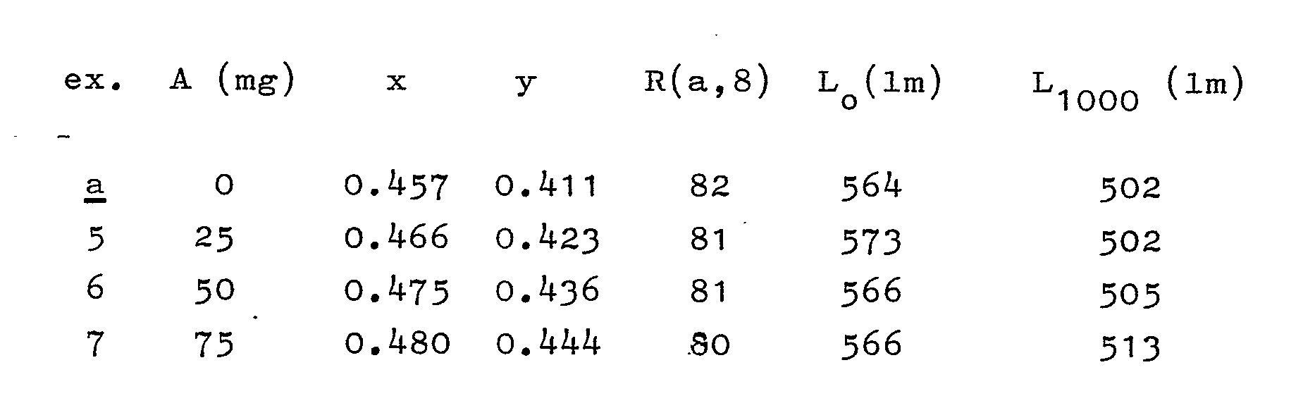
- Three lamps of the kind shown in Fig. 1 (9 W), but without an outer absorption layer, were coated on the inner side of the discharge bulb with an absorption layer of cerium-activated garnet according to the formula Y₂.₉Ce₀.₁Al₅O₁₂. On this absorption layer, a luminescent layer consisting of a mixture of red luminescing Y₂O₃-Eu³⁺ and green luminescing CeMgAl₁₁O₁₉-Tb is provided. In the following table, for each lamp the thickness of the absorption layer A (overall mass of the layer in mg), the colour point (x, y), the value of the general colour rendition index R (a,8), the luminous flux at 0 hours (L₀ in lm) and the luminous flux after 1000 operating hours (L₁₀₀₀ in lm) are indicated. Under ª the values are indicated of the lamp without an absorption layer.
lamps lamps - A lamp of the kind described with reference to Fig. 2 (18 W) was provided with a Y₂.₉Ce₀.₁ Al₅O₁₂-containing absorption layer disposed on the bottom plate on the ballast unit and on the side of the upright edge of the bottom portion facing the discharge bulb. The lamp had a colour point of the emitted radiation x = 0.465 and y = 0.417, which is very close to the desired point (x = 0.468 and y = 0.418). An identical lamp, but without an absorption layer, had a colour point x = 0.461 and y = 0.412.
- Three lamps of the kind described with reference to Fig. 2 (18 W) were provided with a luminescent layer consisting of a mixture of green luminescing terbium-activated cerium magnesium aluminate (CAT), red luminescing yttrium oxide activated by trivalent europium (YOX) and cerium-activated garnet (YAG) according to the formula Y₂.₉Ce₀.₁Al₅O₁₂. In these lamps, the luminescent layer therefore also fulfilled the function of absorption layer. In the following Table, for these lamps the composition of the luminescent layer (in % by weight) is given, while the results of measurements of the colour point (x, y), the colour temperature (Tc in K), luminous efficacy (η in lm/W) and the general colour rendition index R (a, 8) are indicated.

- Finally, it should be noted that the luminescent layer of a lamp according to the invention may comprise besides a red luminescing and a green luminescing material also a small quantity of a blue luminescing material, as is also the case in three-band fluorescent lamps having a high colour temperature. In the present heavily loaded lamps, this can afford advantages because the blue luminescing material provides an additional degree of freedom for reaching a desired value of the colour point of the lamp.
Claims (7)
0.01 ≦ x ≦ 0.15
0 ≦ p ≦ 3
0 ≦ q ≦ 1.
Applications Claiming Priority (2)
| Application Number | Priority Date | Filing Date | Title |
|---|---|---|---|
| NL8502025A NL8502025A (en) | 1985-07-15 | 1985-07-15 | LOW-PRESSURE MERCURY DISCHARGE LAMP. |
| NL8502025 | 1985-07-15 |
Publications (1)
| Publication Number | Publication Date |
|---|---|
| EP0209942A1 true EP0209942A1 (en) | 1987-01-28 |
Family
ID=19846300
Family Applications (1)
| Application Number | Title | Priority Date | Filing Date |
|---|---|---|---|
| EP86201222A Withdrawn EP0209942A1 (en) | 1985-07-15 | 1986-07-14 | Low-pressure mercury vapour discharge lamp |
Country Status (9)
| Country | Link |
|---|---|
| US (1) | US4727283A (en) |
| EP (1) | EP0209942A1 (en) |
| JP (1) | JPS6220237A (en) |
| CN (1) | CN1005879B (en) |
| DD (1) | DD248223A5 (en) |
| ES (1) | ES2000274A6 (en) |
| FI (1) | FI862916L (en) |
| HU (1) | HU194649B (en) |
| NL (1) | NL8502025A (en) |
Cited By (8)
| Publication number | Priority date | Publication date | Assignee | Title |
|---|---|---|---|---|
| EP0276519A1 (en) * | 1987-01-19 | 1988-08-03 | Koninklijke Philips Electronics N.V. | Luminescent lanthanum gallate activated by trivalent thulium, luminescent screen provided with such a gallate and cathode ray tube provided with such a screen |
| EP0335203A1 (en) * | 1988-03-28 | 1989-10-04 | TUNGSRAM Részvénytársaság | Phosphor useful for mercury vapour discharge lamps, and mercury vapour discharge lamp |
| EP0865071A3 (en) * | 1997-03-13 | 1999-02-10 | Matsushita Electric Industrial Co., Ltd. | Warm white fluorescent lamp |
| EP0926106A1 (en) * | 1997-12-16 | 1999-06-30 | Konoshima Chemical Co., Ltd. | A corrosion resistant ceramic and a production method thereof |
| WO2000031207A1 (en) * | 1998-11-26 | 2000-06-02 | Koninklijke Philips Electronics N.V. | Discharge lamp |
| EP1017111A2 (en) | 1996-07-29 | 2000-07-05 | Nichia Chemical Industries, Ltd. | Light emitting device and display |
| JP3938470B2 (en) * | 1997-12-24 | 2007-06-27 | 株式会社日立メディコ | Phosphor, radiation detector using the same, and X-ray CT apparatus |
| US8963182B2 (en) | 1996-03-26 | 2015-02-24 | Cree, Inc. | Solid state white light emitter and display using same |
Families Citing this family (23)
| Publication number | Priority date | Publication date | Assignee | Title |
|---|---|---|---|---|
| US5118985A (en) * | 1989-12-29 | 1992-06-02 | Gte Products Corporation | Fluorescent incandescent lamp |
| US5134336A (en) * | 1991-05-13 | 1992-07-28 | Gte Products Corporation | Fluorescent lamp having double-bore inner capillary tube |
| US5272406A (en) * | 1991-05-13 | 1993-12-21 | Gte Products Corporation | Miniature low-wattage neon light source |
| DE19638667C2 (en) * | 1996-09-20 | 2001-05-17 | Osram Opto Semiconductors Gmbh | Mixed-color light-emitting semiconductor component with luminescence conversion element |
| BR9709998B1 (en) * | 1996-06-26 | 2010-04-20 | semiconductor building element, light irradiator, with luminescence conversion element | |
| US6608332B2 (en) | 1996-07-29 | 2003-08-19 | Nichia Kagaku Kogyo Kabushiki Kaisha | Light emitting device and display |
| JP2927279B2 (en) * | 1996-07-29 | 1999-07-28 | 日亜化学工業株式会社 | Light emitting diode |
| US6613247B1 (en) | 1996-09-20 | 2003-09-02 | Osram Opto Semiconductors Gmbh | Wavelength-converting casting composition and white light-emitting semiconductor component |
| JP3729047B2 (en) * | 1996-12-27 | 2005-12-21 | 日亜化学工業株式会社 | Light emitting diode |
| DE69825135T2 (en) * | 1997-06-11 | 2005-08-11 | Koninklijke Philips Electronics N.V. | FLUORESCENCE LAMP WITH SPECIAL PHOSPHORMISCHEN |
| DE19806213B4 (en) * | 1998-02-16 | 2005-12-01 | Tews, Walter, Dipl.-Chem. Dr.rer.nat.habil. | Compact energy saving lamp |
| DE10063939B4 (en) * | 2000-12-20 | 2005-01-27 | 3M Espe Ag | Dental cement containing a reaction-resistant dental glass and method for its production |
| US6541800B2 (en) | 2001-02-22 | 2003-04-01 | Weldon Technologies, Inc. | High power LED |
| JP3775268B2 (en) * | 2001-09-03 | 2006-05-17 | 日亜化学工業株式会社 | Method for forming light emitting device |
| US6762432B2 (en) * | 2002-04-01 | 2004-07-13 | Micrel, Inc. | Electrical field alignment vernier |
| DE10233768A1 (en) * | 2002-07-25 | 2004-02-12 | Philips Intellectual Property & Standards Gmbh | Lamp system with green-blue gas discharge lamp and yellow-red LED |
| KR100492938B1 (en) * | 2002-09-11 | 2005-05-30 | 강성진 | A compact-type discharge lamp |
| US6903380B2 (en) | 2003-04-11 | 2005-06-07 | Weldon Technologies, Inc. | High power light emitting diode |
| EP1659335A4 (en) * | 2003-08-28 | 2010-05-05 | Mitsubishi Chem Corp | LIGHT EMITTING DEVICE AND PHOSPHORUS |
| TW200512949A (en) * | 2003-09-17 | 2005-04-01 | Nanya Plastics Corp | A method to provide emission of white color light by the principle of secondary excitation and its product |
| KR20060082527A (en) * | 2005-01-12 | 2006-07-19 | 삼성에스디아이 주식회사 | Phosphor and Plasma Display Panel Using the Same |
| ATE528961T1 (en) * | 2005-04-14 | 2011-10-15 | Koninkl Philips Electronics Nv | COLOR CONTROL OF WHITE LEDS |
| JP4843990B2 (en) * | 2005-04-22 | 2011-12-21 | 日亜化学工業株式会社 | Phosphor and light emitting device using the same |
Citations (3)
| Publication number | Priority date | Publication date | Assignee | Title |
|---|---|---|---|---|
| FR2090279A1 (en) * | 1970-05-26 | 1972-01-14 | Ford Motor Co | |
| DE2158492A1 (en) * | 1971-02-08 | 1972-08-17 | Ford Motor Co | Homogeneous cathodoluminescent phosphors |
| DE2739437A1 (en) * | 1976-09-03 | 1978-03-09 | Johnson Matthey Co Ltd | LUMINANT AND PROCESS FOR ITS MANUFACTURING |
Family Cites Families (6)
| Publication number | Priority date | Publication date | Assignee | Title |
|---|---|---|---|---|
| NL164697C (en) * | 1973-10-05 | 1981-01-15 | Philips Nv | LOW-PRESSURE MERCURY DISCHARGE LAMP. |
| NL7406960A (en) * | 1974-05-24 | 1975-11-26 | Philips Nv | PROCEDURE FOR PREPARING A RARE-NATURE ALUMINIATE, ESPECIALLY A LUMINES-CREATING RARE-NATURE ALUMINATE. |
| JPS53136374A (en) * | 1977-05-04 | 1978-11-28 | Hitachi Ltd | Low pressure vapor discharge lamp |
| NL8001833A (en) * | 1980-03-28 | 1981-10-16 | Philips Nv | LOW-PRESSURE MERCURY DISCHARGE LAMP. |
| JPS56143654A (en) * | 1980-04-08 | 1981-11-09 | Toshiba Corp | Fluorescent lamp |
| JPS57174847A (en) * | 1981-04-22 | 1982-10-27 | Mitsubishi Electric Corp | Fluorescent discharge lamp |
-
1985
- 1985-07-15 NL NL8502025A patent/NL8502025A/en not_active Application Discontinuation
-
1986
- 1986-07-08 US US06/883,186 patent/US4727283A/en not_active Expired - Fee Related
- 1986-07-10 HU HU862862A patent/HU194649B/en unknown
- 1986-07-11 CN CN86104700.1A patent/CN1005879B/en not_active Expired
- 1986-07-11 FI FI862916A patent/FI862916L/en not_active IP Right Cessation
- 1986-07-11 ES ES8600260A patent/ES2000274A6/en not_active Expired
- 1986-07-11 DD DD86292399A patent/DD248223A5/en unknown
- 1986-07-14 JP JP61163910A patent/JPS6220237A/en active Pending
- 1986-07-14 EP EP86201222A patent/EP0209942A1/en not_active Withdrawn
Patent Citations (3)
| Publication number | Priority date | Publication date | Assignee | Title |
|---|---|---|---|---|
| FR2090279A1 (en) * | 1970-05-26 | 1972-01-14 | Ford Motor Co | |
| DE2158492A1 (en) * | 1971-02-08 | 1972-08-17 | Ford Motor Co | Homogeneous cathodoluminescent phosphors |
| DE2739437A1 (en) * | 1976-09-03 | 1978-03-09 | Johnson Matthey Co Ltd | LUMINANT AND PROCESS FOR ITS MANUFACTURING |
Cited By (50)
| Publication number | Priority date | Publication date | Assignee | Title |
|---|---|---|---|---|
| EP0276519A1 (en) * | 1987-01-19 | 1988-08-03 | Koninklijke Philips Electronics N.V. | Luminescent lanthanum gallate activated by trivalent thulium, luminescent screen provided with such a gallate and cathode ray tube provided with such a screen |
| EP0335203A1 (en) * | 1988-03-28 | 1989-10-04 | TUNGSRAM Részvénytársaság | Phosphor useful for mercury vapour discharge lamps, and mercury vapour discharge lamp |
| US9698313B2 (en) | 1996-03-26 | 2017-07-04 | Cree, Inc. | Solid state white light emitter and display using same |
| US8963182B2 (en) | 1996-03-26 | 2015-02-24 | Cree, Inc. | Solid state white light emitter and display using same |
| US7855092B2 (en) | 1996-07-29 | 2010-12-21 | Nichia Corporation | Device for emitting white-color light |
| EP2197057A2 (en) | 1996-07-29 | 2010-06-16 | Nichia Corporation | Light emitting device and display |
| US7026756B2 (en) | 1996-07-29 | 2006-04-11 | Nichia Kagaku Kogyo Kabushiki Kaisha | Light emitting device with blue light LED and phosphor components |
| US7071616B2 (en) | 1996-07-29 | 2006-07-04 | Nichia Kagaku Kogyo Kabushiki Kaisha | Light emitting device with blue light led and phosphor components |
| US7126274B2 (en) | 1996-07-29 | 2006-10-24 | Nichia Corporation | Light emitting device with blue light LED and phosphor components |
| US7215074B2 (en) | 1996-07-29 | 2007-05-08 | Nichia Corporation | Light emitting device with blue light led and phosphor components |
| US7329988B2 (en) | 1996-07-29 | 2008-02-12 | Nichia Corporation | Light emitting device with blue light LED and phosphor components |
| EP1017111A2 (en) | 1996-07-29 | 2000-07-05 | Nichia Chemical Industries, Ltd. | Light emitting device and display |
| US9130130B2 (en) | 1996-07-29 | 2015-09-08 | Nichia Corporation | Light emitting device and display comprising a plurality of light emitting components on mount |
| EP2276080B1 (en) | 1996-07-29 | 2015-07-08 | Nichia Corporation | Light emitting device and display |
| US7362048B2 (en) | 1996-07-29 | 2008-04-22 | Nichia Kagaku Kogyo Kabushiki Kaisha | Light emitting device with blue light led and phosphor components |
| CN100449807C (en) * | 1996-07-29 | 2009-01-07 | 日亚化学工业株式会社 | Light emitting device and display device |
| US7531960B2 (en) | 1996-07-29 | 2009-05-12 | Nichia Corporation | Light emitting device with blue light LED and phosphor components |
| US7682848B2 (en) | 1996-07-29 | 2010-03-23 | Nichia Corporation | Light emitting device with blue light LED and phosphor components |
| EP2194590A2 (en) | 1996-07-29 | 2010-06-09 | Nichia Corporation | Light emitting device and display |
| US7915631B2 (en) | 1996-07-29 | 2011-03-29 | Nichia Corporation | Light emitting device and display |
| EP2197056A2 (en) | 1996-07-29 | 2010-06-16 | Nichia Corporation | Light emitting device and display |
| EP2197055A2 (en) | 1996-07-29 | 2010-06-16 | Nichia Corporation | Light emitting device and display |
| EP2197054A2 (en) | 1996-07-29 | 2010-06-16 | Nichia Corporation | Light emitting device and display |
| EP2197053A2 (en) | 1996-07-29 | 2010-06-16 | Nichia Corporation | Light emitting device and display |
| EP1017111A3 (en) * | 1996-07-29 | 2004-04-14 | Nichia Chemical Industries, Ltd. | Light emitting device and display |
| EP2276080A2 (en) | 1996-07-29 | 2011-01-19 | Nichia Corporation | Light emitting device and display |
| SG115349A1 (en) * | 1996-07-29 | 2005-10-28 | Nichia Corp | Light emitting device and display |
| US7901959B2 (en) | 1996-07-29 | 2011-03-08 | Nichia Corporation | Liquid crystal display and back light having a light emitting diode |
| US8754428B2 (en) | 1996-07-29 | 2014-06-17 | Nichia Corporation | Light emitting device and display |
| US7969090B2 (en) | 1996-07-29 | 2011-06-28 | Nichia Corporation | Light emitting device and display |
| US7968866B2 (en) | 1996-07-29 | 2011-06-28 | Nichia Corporation | Light emitting device and display |
| US8148177B2 (en) | 1996-07-29 | 2012-04-03 | Nichia Corporation | Light emitting device and display |
| US8309375B2 (en) | 1996-07-29 | 2012-11-13 | Nichia Corporation | Light emitting device and display |
| EP2276080A3 (en) * | 1996-07-29 | 2013-01-09 | Nichia Corporation | Light emitting device and display |
| EP2197054A3 (en) * | 1996-07-29 | 2013-01-16 | Nichia Corporation | Light emitting device and display |
| EP2197055A3 (en) * | 1996-07-29 | 2013-01-16 | Nichia Corporation | Light emitting device and display |
| EP2194590A3 (en) * | 1996-07-29 | 2013-01-23 | Nichia Corporation | Light emitting device and display |
| EP2197056A3 (en) * | 1996-07-29 | 2013-01-23 | Nichia Corporation | Light emitting device and display |
| EP2197057A3 (en) * | 1996-07-29 | 2013-01-23 | Nichia Corporation | Light emitting device and display |
| US8610147B2 (en) | 1996-07-29 | 2013-12-17 | Nichia Corporation | Light emitting device and display comprising a plurality of light emitting components on mount |
| US8679866B2 (en) | 1996-07-29 | 2014-03-25 | Nichia Corporation | Light emitting device and display |
| US8685762B2 (en) | 1996-07-29 | 2014-04-01 | Nichia Corporation | Light emitting device and display |
| US7943941B2 (en) | 1996-07-29 | 2011-05-17 | Nichia Corporation | Device for emitting various colors |
| EP1271664A3 (en) * | 1996-07-29 | 2004-03-31 | Nichia Chemical Industries, Ltd. | Light emitting device |
| EP2197053B1 (en) | 1996-07-29 | 2015-07-01 | Nichia Corporation | Light emitting device and display |
| US6157126A (en) * | 1997-03-13 | 2000-12-05 | Matsushita Electric Industrial Co., Ltd. | Warm white fluorescent lamp |
| EP0865071A3 (en) * | 1997-03-13 | 1999-02-10 | Matsushita Electric Industrial Co., Ltd. | Warm white fluorescent lamp |
| EP0926106A1 (en) * | 1997-12-16 | 1999-06-30 | Konoshima Chemical Co., Ltd. | A corrosion resistant ceramic and a production method thereof |
| JP3938470B2 (en) * | 1997-12-24 | 2007-06-27 | 株式会社日立メディコ | Phosphor, radiation detector using the same, and X-ray CT apparatus |
| WO2000031207A1 (en) * | 1998-11-26 | 2000-06-02 | Koninklijke Philips Electronics N.V. | Discharge lamp |
Also Published As
| Publication number | Publication date |
|---|---|
| US4727283A (en) | 1988-02-23 |
| NL8502025A (en) | 1987-02-02 |
| FI862916A7 (en) | 1987-01-16 |
| DD248223A5 (en) | 1987-07-29 |
| ES2000274A6 (en) | 1988-02-01 |
| FI862916A0 (en) | 1986-07-11 |
| HUT41558A (en) | 1987-04-28 |
| JPS6220237A (en) | 1987-01-28 |
| HU194649B (en) | 1988-02-29 |
| CN1005879B (en) | 1989-11-22 |
| FI862916L (en) | 1987-01-16 |
| CN86104700A (en) | 1987-01-14 |
Similar Documents
| Publication | Publication Date | Title |
|---|---|---|
| US4727283A (en) | Low-pressure mercury vapour discharge lamp | |
| EP1429370B1 (en) | Blue-green phosphor for fluorescent lighting applications | |
| US7119488B2 (en) | Optimized phosphor system for improved efficacy lighting sources | |
| US6222312B1 (en) | Fluorescent lamp having wide bandwidth blue-green phosphor | |
| EP0215524B1 (en) | High-pressure mercury vapour discharge lamp | |
| US4065688A (en) | High-pressure mercury-vapor discharge lamp having a light output with incandescent characteristics | |
| US3937998A (en) | Luminescent coating for low-pressure mercury vapour discharge lamp | |
| EP1429369B1 (en) | Red phosphors for use in high cri fluorescent lamps | |
| CA2470301C (en) | Discharge lamp having two-band phosphor | |
| US4029983A (en) | Metal-halide discharge lamp having a light output with incandescent characteristics | |
| EP0124175B1 (en) | Low-pressure mercury vapour discharge lamp | |
| EP0229428B1 (en) | Low-pressure mercury vapour discharge lamp | |
| JPH05334999A (en) | Low-pressure mercury discharge lamp | |
| US4751426A (en) | Fluorescent lamp using multi-layer phosphor coating | |
| US5159237A (en) | Green-light-emitting rare gas discharge lamp | |
| WO2008129489A2 (en) | Fluorescent mercury vapor discharge lamp comprising trichromatic phosphor blend | |
| CA1207005A (en) | Long life, warm color metal halide arc discharge lamp | |
| CA1081306A (en) | Low-pressure mercury vapour discharge lamp | |
| EP2600387A1 (en) | Fluorescent lamps having high CRI | |
| JPH0864173A (en) | Mercury vapor discharge lamp and lighting device using the same | |
| JPH0228283A (en) | Fluorescent material for white-luminescent rare gas discharge lamp and the same lamp | |
| JPH04298956A (en) | Rare gas discharge lamp | |
| JPS6351347B2 (en) | ||
| JPH01256585A (en) | Phosphor and fluorescent lamp | |
| GB1599964A (en) | High-pressure mercury-vapour discharge lamps |
Legal Events
| Date | Code | Title | Description |
|---|---|---|---|
| PUAI | Public reference made under article 153(3) epc to a published international application that has entered the european phase |
Free format text: ORIGINAL CODE: 0009012 |
|
| AK | Designated contracting states |
Kind code of ref document: A1 Designated state(s): AT BE CH DE FR GB IT LI NL SE |
|
| 17P | Request for examination filed |
Effective date: 19870525 |
|
| 17Q | First examination report despatched |
Effective date: 19881020 |
|
| STAA | Information on the status of an ep patent application or granted ep patent |
Free format text: STATUS: THE APPLICATION IS DEEMED TO BE WITHDRAWN |
|
| 18D | Application deemed to be withdrawn |
Effective date: 19890503 |
|
| RIN1 | Information on inventor provided before grant (corrected) |
Inventor name: HEUVELMANS, JEAN JOHAN Inventor name: SIEBERS, GERARDUS HENRICUS MARIA Inventor name: VAN KEMENADE, JOHANNES TRUDO CORNELIS Inventor name: DE HAIR, JOHANNES THEODORUS WILHELMUS Inventor name: TER VRUGT, JOHANNES WILHELMUS |