EP0209834B1 - Text and graphics image setting apparatus - Google Patents
Text and graphics image setting apparatus Download PDFInfo
- Publication number
- EP0209834B1 EP0209834B1 EP86109687A EP86109687A EP0209834B1 EP 0209834 B1 EP0209834 B1 EP 0209834B1 EP 86109687 A EP86109687 A EP 86109687A EP 86109687 A EP86109687 A EP 86109687A EP 0209834 B1 EP0209834 B1 EP 0209834B1
- Authority
- EP
- European Patent Office
- Prior art keywords
- photosensitive material
- image
- photosensitive
- sheet material
- light
- Prior art date
- Legal status (The legal status is an assumption and is not a legal conclusion. Google has not performed a legal analysis and makes no representation as to the accuracy of the status listed.)
- Expired - Lifetime
Links
Images


Classifications
-
- G—PHYSICS
- G06—COMPUTING OR CALCULATING; COUNTING
- G06K—GRAPHICAL DATA READING; PRESENTATION OF DATA; RECORD CARRIERS; HANDLING RECORD CARRIERS
- G06K15/00—Arrangements for producing a permanent visual presentation of the output data, e.g. computer output printers
- G06K15/02—Arrangements for producing a permanent visual presentation of the output data, e.g. computer output printers using printers
- G06K15/12—Arrangements for producing a permanent visual presentation of the output data, e.g. computer output printers using printers by photographic printing, e.g. by laser printers
- G06K15/1204—Arrangements for producing a permanent visual presentation of the output data, e.g. computer output printers using printers by photographic printing, e.g. by laser printers involving the fast moving of an optical beam in the main scanning direction
-
- B—PERFORMING OPERATIONS; TRANSPORTING
- B41—PRINTING; LINING MACHINES; TYPEWRITERS; STAMPS
- B41B—MACHINES OR ACCESSORIES FOR MAKING, SETTING, OR DISTRIBUTING TYPE; TYPE; PHOTOGRAPHIC OR PHOTOELECTRIC COMPOSING DEVICES
- B41B19/00—Photoelectronic composing machines
Definitions
- the present invention pertains to image setting and, more particularly, to an apparatus and method for providing high quality images on photosensitive material.
- printers including those classified as dot matrix printers, have already been developed. Most of such printers have typical dot matrix resolutions of 39,37 dots per cm (100 dots per inch) or less, although some of them apparently provide 118,11 dots per cm (300 dpi), which is considered high quality for printers.
- laser phototypesetters can provide writing resolutions between 283,46 (720) and 984,25 dots per cm (2500 dpi), with the bulk of them having resolutions lying in the range of 383,85 (975) to 472,44 dots per cm (1200 dpi).
- Another, more specific object is to facilitate the production of output images having widths equal to or greater than 30,48 cm (72 picas, 12 inches).
- Another specific object is to set images at resolutions ranging up to 944,88 dots per cm (2400 dpi) and at a speed of over 170 rasters per second, which corresponds to 2,54cm (one inch) of output every seven seconds at 472,44 dots per cm (1200 dpi) and proportionately shorter times at coarser resolutions.
- the patent 4,284,994 does generally set forth a scheme or system involving a laser beam containing input information, and including means for reflecting that beam through a scan lens system, a polygonal mirror functioning to produce a scan beam with constant angular velocity.
- the scan lens acts in response to the scan beam to provide an image point that moves across the film with a constant velocity.
- a mechanical scanner moves the film either continuously or in discrete steps, thereby to provide the other dimension of the requisite two-dimensional image.
- Another more specific object is to achieve an efficient compromise between speed and alignment requirements in producing high quality images on photosensitive material.
- Yet another specific object is to enable more efficient use of the laser light energy available by providing that the prism mirror involved in the optical arrangement achieves a relatively longer dwell time on the photosensitive material than conventional systems.
- a primary feature of the present invention lies in a unique combination of phototypesetting apparatus, comprising means for transporting such photosensitive sheet material past an image point to provide a first dimension of said two-dimensional image on said photosensitive material; a light source for producing a modulated beam of light; a rotatable convex prism, having two outwardly directed mirror facets whose planes intersect in a common line and having its axis of rotation perpendicular to said line, for reflecting said light beam into a scanning beam with a substantially constant angular velocity; and scan lens means in the path of said scanning beam such that a focused beam spot moves repeatedly in a linear direction across said photosensitive material at said image point to provide the other dimension of said two-dimensional image on said photosensitive material.
- An improvement of the invention resides in the fact that the source of light comprises a laser diode emitting a coherent light beam, such beam being modulated in response to an electrical signal representative of the image to be developed.
- Another improvement of the present invention resides in the mounting means for the particular prism mirror or "spinner" utilized in the optic system. Because there are two mirror facets involved in the device, only one degree of freedom adjustment is necessary. Accordingly, a simple adjusting means ensures that the beam from both facets will hit the photosensitive sheet material at the same place.
- Another improvement of the present invention relates to a unique film transport mechanism.
- the film is unwound from a suitable reel housed in a receptacle or cassette and the film is moved between drive rollers. It is then moved past a device for cutting the film and to an output receptacle where the film may be rolled up, if desired, by a suitable reel or may be left in an unwound state.
- a further improvement of the invention is an arrangement involving a stepping motor which drives through a worm gear and worm wheel so as to enable simple direct control of position from a suitable electronic control system.
- a worm gear arrangement contributes to stability, and the phototypesetting system can achieve precision without high tolerance manufacturing requirements or precision assembly requirements.
- Fig.1 is a perspective view of the complete apparatus including a housing in which the present invention is incorporated.
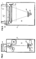
- Fig. 2 is a schematic representation of the principal components of the phototypesetting system of the present invention depicted from a side view of the housing of Fig. 1.
- Fig. 3 is a similar depiction, that is another schematic representation as in Fig. 2, but seen from the front.
- Fig. 4 is a perspective view of some of the principal components of the system, particularly indicating the movement of an image point on a film plane responsive to light from a source us reflected by a mirror system through a lens means.
- Fig. 5 is a fragmentary end view of the mirror or "spinner" in accordance with the present invention, particularly illustrating the adjustable mounting means for such mirror.
- Figs. 6,7 and 8 are front view, top view, and rear view, respectively, of the adjusting arrangement for the mounting means illustrated in Fig. 5.
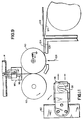
- Fig. 9 is an elevational view of the transport mechanism for the photosensitive material on which images are set in accordance with the present invention.
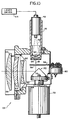
- Fig. 10 is a side elevational view of the complete laser scanning system of the present invention.
- Fig. 11 is a detailed view showing the adjustable means for providing an aperture in the path of the lens of the system.
- FIG. 1 a perspective view of the complete apparatus; also, schematic diagrams of side and front views of phototypesetting apparatus 10 arranged in accordance with the present invention to provide a two-dimensional image from an electrical representation of such image.
- the apparatus 10 is contained in a housing 12 at the top of which there is provided a receptacle 14 for receiving the photosensitive material on which images have been set.
- a rotatable prism mirror reflects the beam 18 to a scan lens 22 through which the beam passes to an image point on the photosensitive material 24.
- the rotatable prism mirror 20 is provided with two mirror facets 32 and 34 (Fig. 4), such facets being joined in a common line 30 in accordance with this triangular prism construction.
- the mirror or spinner 20 is driven by a high speed synchronous motor 36 whose speed is constant on the average but is subject to a limited amount of jitter and wander.
- the beam emanating from the scan lens 22 causes a focused spot 38 to move in rasterlike fashion along an image plane of the film 24.
- the beam angle ⁇ that is swept out during imaging by a given mirror facet - i.e., either the facet 32 or the facet 34 - is approximately 60°.
- information contained in the modulated laser beam is laid down on the film. It will of course be understood that the beam sweep caused by the facet 34 occurs one half a revolution of the mirror 20 later than the beam sweep caused by the facet 32. In between these two active periods there are dead times of approximately 120° each.
- the source 16 includes a laser diode 48 housed in a suitable container and providing a source of coherent light 50 which is transmitted through collimator lenses 52 and 54.
- the collimator may be replaced by other beam controlling means.
- a component not mentioned previously is an adjustably rotatable plate 56 (Fig. 11) containing a slotted aperture 58.
- the plate 56 is rotated by means of a rotary solenoid 60 having a suitable shaft attached to one end of plate 56.
- the slotted opening 58 in the aperture plate 56 is oriented such that the long dimension of the elliptical spot on the film plane is arranged vertically with respect to the imaged text or graphics on the photosensitive film. With the aperture in place, the elongated spot will ensure proper fill-in between successive scan lines as the film is advanced with a coarse vertical resolution (e.g., 800 lines per inch or less). When the film is advanced with a fine resolution (up to 2,400 lpi), the aperture plate is removed so that the focused spot remains round and small.
- a coarse vertical resolution e.g. 800 lines per inch or less.
- Actuation of the rotary solenoid 60 can take place automatically, in dependence upon the operator's selection of the vertical resolution, or it can be controlled independently by the operator.
- the scan lens 22 which preferably is made up of three individual lenses, operates in accordance with the principles described in the aforementioned U.S. Patent No. 3,687,025 to Rosin.
- the scan lens 22 focuses the beam onto the photosensitive surface while compensating for any variations in image focus introduced by deviations of the beam from the optical axis.
- the mirror scanner 20 is mounted to be driven at high speed by a motor 36, a hub 74 being provided to lock onto the end of the motor shaft.
- the mirror scanner 20 is glued onto a base 76 which is integrally formed with the hub 74.
- two tapered bores 80 extend through the base 76.
- Two suitably tapered adjusting screws 82 are adapted to be fitted within the bores 80. Movement in and out of these adjusting screws results in appropriate tilting of the mirror scanner 20 with reference to the axis of rotation.
- Two further screws 78 are provided so as to tightly clamp the screws 82 between the two halves of the base 76, after each repositioning of these screws 82. Consequently, the one degree of freedom adjustment that is necessary with this two faceted mirror scanner can be readily accomplished.
- FIG. 9 there are shown some further details of the transport mechanism for transporting the photosensitive sheet material or film 24 previously seen in Figs. 2 and 3.
- the film 24 is fed to the nip of the pair of rollers 90 and 92, the latter being driven by a motor-worm gear arrangement 94 (Fig. 2).
- a cutting device 96 already noted is provided for cutting the photosensitive material 24 after it emerges from the rollers, at the conclusion of a typesetting "run". It consists of a rotatable blade 97 or the like, controlled either by a manual lever 98 (Fig. 1) or by a motor, which coacts with a stationary blade 99.
- control electronics are provided, particularly video or scanning controls and stepping controls.
- the photoelectric detector 110 senses the lateral position of the beam spot 38 on the image plane and provides an electrical pulse to a programmable delay stage 112 and a beam switching circuit 113.
- the beam switch circuit is connected to a laser driver (amplifier) 114 which supplies controlled power to the laser diode.
- the beam switching circuit 113 blanks (switches off) the laser diode during the period following receipt of a pulse from the photodetector 110 until the delayed pulse is produced by the delay stage 112. Once the delayed pulse is received, the beam switching circuit switches the laser diode on and off in accordance with the incoming data representative of the images to be produced on the photosensitive film.
- the beam switching times are synchronized and controlled by a free-running, stable 15 MHz oscillator.
- the laser driver 114 is capable of supplying a controlled amount of power to the laser diode, thus permitting variation in the intensity of the beam.
- the power may be positioned at any one of eight different levels, these levels being selected during manufacture of the machine from among 256 different potential levels (providing precision).
- the power level may be selected automatically upon selection of the vertical resolution by the operator, or can be selected manually, thus overriding the default selection by the machine.
- the film 24 may be selected to be a silver halide coated film or paper and may be of the type requiring standard processing. In the event that a laser diode is used for the source 16 it is necessary to use infrared sensitive film. Such film is available from Eastman Kodak Co., Rochester, New York under the designation: D2622; Record 40302; 12" x 150', Spec. 175.
- Vertical stepping resolution can be selected from among eight different levels from a value of 2,400 lines per inch (maximum) to 240 lpi (minimum).
- a typical vertical stepping rate is 173.6 rasters per second (equivalent to 8.7 inches per minute at 1,200 lpi resolution).
- the attainable accuracy is ⁇ 0.2% cumulative.
- the horizontal scanning resolution is selectable by a controller up to 2,400 dpi maximum.
- a 15 MHz internal clock is utilized, the average data rate being 5 MHz for 2,400 dpi resolution, 2.5 MHz for 1,200 dpi, etc.
- the duty cycle is 33% for full measure.
- the horizontal scanning measure is 310 mm. maximum with the linearity equal to ⁇ 0.5 point.
- the operator can also cause the machines to use only one fact of the prism mirror. This avoids any possible loss of quality due to misalignment of the facets.
- the spot size for the imaging on the film 24 is 25 microns nominal, with 25 x 50 microns selectable by means of the adjustable aperture.
- the spot power is 250 ergs/sq. cm maximum, at the film plane, and selectable from among 256 levels down to 50 ergs/sq. cm minimum.
- the scanning motor is a reluctance, synchronous motor designed to minimize jitter and wander. A hysteresis synchronous motor can also be used.
Landscapes
- Physics & Mathematics (AREA)
- Engineering & Computer Science (AREA)
- Optics & Photonics (AREA)
- General Engineering & Computer Science (AREA)
- General Physics & Mathematics (AREA)
- Theoretical Computer Science (AREA)
- Laser Beam Printer (AREA)
- Facsimile Scanning Arrangements (AREA)
- Exposure And Positioning Against Photoresist Photosensitive Materials (AREA)
- Mechanical Optical Scanning Systems (AREA)
Description
- The present invention pertains to image setting and, more particularly, to an apparatus and method for providing high quality images on photosensitive material.
- To enable one skilled in the art to appreciate the context and the significance of the improvements involved in accordance with the present invention, reference may be made to the following background information, specifically to the following U.S. patents:
U.S. Patent No. 3,514,534 - Korpel
U.S. Patent No. 3,687,025 - Rosin
U.S. Patent No. 3,698,006 - Ovshinsky
U.S. Patent No. 3,700,911 - Wildhaber
U.S. Patent No. 3,702,094 - Sinnott et al.
U.S. Patent No. 3,710,698 - Sinnott et al.
U.S. Patent No. 3,820,123 - Ammann
U.S. Patent No. 3,827,063 - Sinnott et al.
U.S. Patent No. 3,898,627 - Hooker et al.
U.S. Patent No. 3,995,147 - Sinnott et al.
U.S. Patent No. 4,000,493 - Spaulding et al.
U.S. Patent No. 4,037,231 - Broyles et al.
U.S. Patent No. 4,044,363 - Morgan
U.S. Patent No. 4,053,898 - Hirayama et al.
U.S. Patent No. 4,089,008 - Saga et al.
U.S. Patent No. 4,122,462 - Hirayama et al.
U.S. Patent No. 4,200,369 - Richards et al.
U.S. Patent No. 4,222,643 - Kitamura et al.
U.S. Patent No. 4,232,954 - Kitamura et al.
U.S. Patent No. 4,277,154 - Sakabinos
U.S. Patent No. 4,284,994 - Radl
U.S. Patent No. 4,290,689 - Kleinschnitz, Jr.
U.S. Patent No. 4,293,202 - Ohnishi et al.
U.S. Patent No. 4,299,458 - Burton et al.
U.S. Patent No. 4,305,646 - Bechtold
U.S. Patent No. 4,419,676 - Lenk et al.
U.S. Patent No. 4,450,453 - Kitamura et al. - From the references cited, it will be appreciated that a variety of printers, including those classified as dot matrix printers, have already been developed. Most of such printers have typical dot matrix resolutions of 39,37 dots per cm (100 dots per inch) or less, although some of them apparently provide 118,11 dots per cm (300 dpi), which is considered high quality for printers. On the other hand, laser phototypesetters can provide writing resolutions between 283,46 (720) and 984,25 dots per cm (2500 dpi), with the bulk of them having resolutions lying in the range of 383,85 (975) to 472,44 dots per cm (1200 dpi).
- Nevertheless, what has been lacking in the field is a cost-effective apparatus for achieving the requisite high degree of resolution in image setting.
- It is therefore a primary object of the present invention to provide a low-cost, high-resolution, image setter for reproduction-quality imaging.
- Another, more specific object is to facilitate the production of output images having widths equal to or greater than 30,48 cm (72 picas, 12 inches).
- Another specific object is to set images at resolutions ranging up to 944,88 dots per cm (2400 dpi) and at a speed of over 170 rasters per second, which corresponds to 2,54cm (one inch) of output every seven seconds at 472,44 dots per cm (1200 dpi) and proportionately shorter times at coarser resolutions.
- It is well known that laser typesetters utilizing multifaceted mirrors, in conjunction with a conventional optical system, require that each and every facet be corrected individually to match each other due to the practical limitations of facet manufacturing tolerances.
- In this regard, particular reference may be made to the aforementioned U.S. Patent No. 4,284,994. The invention described therein relates to laser beam recorders or printers using a polygonal mirror as a scanning device, the improvement being particularly directed to an optical system for compensating tilted facets of the polygonal mirror.
- The patent 4,284,994 does generally set forth a scheme or system involving a laser beam containing input information, and including means for reflecting that beam through a scan lens system, a polygonal mirror functioning to produce a scan beam with constant angular velocity. The scan lens acts in response to the scan beam to provide an image point that moves across the film with a constant velocity. Concurrently or alternately with the movement of the scan beam, a mechanical scanner moves the film either continuously or in discrete steps, thereby to provide the other dimension of the requisite two-dimensional image.
- Conventional laser typesetters have generally used gas lasers, such as helium-neon lasers, in their operation. Not only are such lasers, with their accompanying power supply, modulator and modulator driver relatively expensive, hut the helium-neon laser, in particular, suffers from the fact that the peak modulation rate is limited by the size of the output beam. Only with further optics improvements, involving additional cost, can the modulation performance be improved.
- In contrast thereto, currently available laser diodes in the milliwatt range can readily be modulated in an image setter at rates of at least 20 MHz. Accordingly, it is a primary object of the present invention to judiciously exploit, by a unique combination of apparatus, the capability of such laser diodes with high modulation rates.
- Another more specific object is to achieve an efficient compromise between speed and alignment requirements in producing high quality images on photosensitive material.
- Yet another specific object is to enable more efficient use of the laser light energy available by providing that the prism mirror involved in the optical arrangement achieves a relatively longer dwell time on the photosensitive material than conventional systems.
- In previously known phototypesetters a serious drawback involved the structure of the apparatus for receiving the image and transporting the film. Frequently the prior art mechanisms for film transport involve a relatively long film path from the point at which the film is removed from a film supply cassette and moved past the optical system to the point at which it is rewound on an output reel or the like.
- It is therefore another primary object of the present invention to eliminate the wastage in photosensitive material involved in the long path from input to output points.
- In fulfillment of the above-stated objects, a primary feature of the present invention lies in a unique combination of phototypesetting apparatus, comprising means for transporting such photosensitive sheet material past an image point to provide a first dimension of said two-dimensional image on said photosensitive material; a light source for producing a modulated beam of light; a rotatable convex prism, having two outwardly directed mirror facets whose planes intersect in a common line and having its axis of rotation perpendicular to said line, for reflecting said light beam into a scanning beam with a substantially constant angular velocity; and scan lens means in the path of said scanning beam such that a focused beam spot moves repeatedly in a linear direction across said photosensitive material at said image point to provide the other dimension of said two-dimensional image on said photosensitive material.
- An improvement of the invention resides in the fact that the source of light comprises a laser diode emitting a coherent light beam, such beam being modulated in response to an electrical signal representative of the image to be developed.
- Another improvement of the present invention resides in the mounting means for the particular prism mirror or "spinner" utilized in the optic system. Because there are two mirror facets involved in the device, only one degree of freedom adjustment is necessary. Accordingly, a simple adjusting means ensures that the beam from both facets will hit the photosensitive sheet material at the same place.
- Another improvement of the present invention relates to a unique film transport mechanism. The film is unwound from a suitable reel housed in a receptacle or cassette and the film is moved between drive rollers. It is then moved past a device for cutting the film and to an output receptacle where the film may be rolled up, if desired, by a suitable reel or may be left in an unwound state. By keeping the film path short from input to output, and particularly by writing directly on the film passing under one of the aforesaid drive rollers, a high degree of economy in photo material usage is effected.
- A further improvement of the invention is an arrangement involving a stepping motor which drives through a worm gear and worm wheel so as to enable simple direct control of position from a suitable electronic control system. Such a worm gear arrangement contributes to stability, and the phototypesetting system can achieve precision without high tolerance manufacturing requirements or precision assembly requirements.
- Other and further objects, advantages and features of the present invention will be understood by reference to the following specification in conjunction with the annexed drawings, wherein like parts have been given like numbers.
- Fig.1 is a perspective view of the complete apparatus including a housing in which the present invention is incorporated.
- Fig. 2 is a schematic representation of the principal components of the phototypesetting system of the present invention depicted from a side view of the housing of Fig. 1.
- Fig. 3 is a similar depiction, that is another schematic representation as in Fig. 2, but seen from the front.
- Fig. 4 is a perspective view of some of the principal components of the system, particularly indicating the movement of an image point on a film plane responsive to light from a source us reflected by a mirror system through a lens means.
- Fig. 5 is a fragmentary end view of the mirror or "spinner" in accordance with the present invention, particularly illustrating the adjustable mounting means for such mirror.
- Figs. 6,7 and 8 are front view, top view, and rear view, respectively, of the adjusting arrangement for the mounting means illustrated in Fig. 5.
- Fig. 9 is an elevational view of the transport mechanism for the photosensitive material on which images are set in accordance with the present invention.
- Fig. 10 is a side elevational view of the complete laser scanning system of the present invention.
- Fig. 11 is a detailed view showing the adjustable means for providing an aperture in the path of the lens of the system.
- Referring to the figures of the drawing and particularly for the moment to Figs. 1-3, there is shown a perspective view of the complete apparatus; also, schematic diagrams of side and front views of
phototypesetting apparatus 10 arranged in accordance with the present invention to provide a two-dimensional image from an electrical representation of such image. Theapparatus 10 is contained in ahousing 12 at the top of which there is provided areceptacle 14 for receiving the photosensitive material on which images have been set. - Within the
housing 12 are contained the primary components seen schematically in Figs. 2 and 3. These components include a source of light 16 from which there is emitted a modulatedbeam 18. A rotatable prism mirror reflects thebeam 18 to ascan lens 22 through which the beam passes to an image point on thephotosensitive material 24. - It is to be especially noted that the
rotatable prism mirror 20 is provided with twomirror facets 32 and 34 (Fig. 4), such facets being joined in acommon line 30 in accordance with this triangular prism construction. The mirror orspinner 20 is driven by a high speedsynchronous motor 36 whose speed is constant on the average but is subject to a limited amount of jitter and wander. - It will be appreciated that as the prism mirror or
spinner 20 is rotated, the beam emanating from thescan lens 22 causes afocused spot 38 to move in rasterlike fashion along an image plane of thefilm 24. The beam angle ϑ that is swept out during imaging by a given mirror facet - i.e., either thefacet 32 or the facet 34 - is approximately 60°. During this period, information contained in the modulated laser beam is laid down on the film. It will of course be understood that the beam sweep caused by thefacet 34 occurs one half a revolution of themirror 20 later than the beam sweep caused by thefacet 32. In between these two active periods there are dead times of approximately 120° each. During these dead times the electronic circuitry of the system switches the scanning beam on so that the beginning sweep can be detected by aphotocell 110. Given a prescribed speed of themotor 36, it will be manifest that the scanning time in rastering with the prism mirror or "spinner", according to the invention, is longer by a factor of two when compared with the scanning time for a conventional, polygonal mirror, thereby increasing the dwell time of the beam on the photosensitive film. In the prior systems exemplified by U.S. Patent No. 4,204,994, only half the angle swept out by a given mirror facet is utilized because of the 2:1 ratio between the angle of rotation and the angle of the scanning beam. - Referring now to Fig. 10, there will be seen further details of the scanning system in accordance with the preferred embodiment. In this figure it will be noted that the
source 16 includes alaser diode 48 housed in a suitable container and providing a source of coherent light 50 which is transmitted throughcollimator lenses - A component not mentioned previously is an adjustably rotatable plate 56 (Fig. 11) containing a slotted
aperture 58. Theplate 56 is rotated by means of arotary solenoid 60 having a suitable shaft attached to one end ofplate 56. Thisadjustable aperture plate 56 is an optional feature, according to the invention; however, it is useful for tailoring or controlling the spot size and spot shape at the photosensitive sheet material. It will be understood that although a slottedopening 58 is shown, this opening can be round if desired. By use of this aperture plate a nominal 25 micron spot can be enlarged to an elliptical 25 by 50 micron spot at the image point on the photosensitive material (where 25.4 microns = 1/1000 inches). - The slotted
opening 58 in theaperture plate 56 is oriented such that the long dimension of the elliptical spot on the film plane is arranged vertically with respect to the imaged text or graphics on the photosensitive film. With the aperture in place, the elongated spot will ensure proper fill-in between successive scan lines as the film is advanced with a coarse vertical resolution (e.g., 800 lines per inch or less). When the film is advanced with a fine resolution (up to 2,400 lpi), the aperture plate is removed so that the focused spot remains round and small. - Actuation of the
rotary solenoid 60 can take place automatically, in dependence upon the operator's selection of the vertical resolution, or it can be controlled independently by the operator. - The
scan lens 22, which preferably is made up of three individual lenses, operates in accordance with the principles described in the aforementioned U.S. Patent No. 3,687,025 to Rosin. In particular, the scan lens is constructed and arranged to adjust the beam according to the relationship y' = f ϑ, where y' is the distance of the image from the intersection of the axis of the scan lens and the image plane, f is the effective focal length of the scan lens to the image plane, and ϑ is the angle between the beam and the optical axis of the scan lens. Thescan lens 22 focuses the beam onto the photosensitive surface while compensating for any variations in image focus introduced by deviations of the beam from the optical axis. - Because of the fact that the
mirror scanner 20 is provided with only two facets, easy adjustment can be made to insure that the scanning beam from both facets will strike thephotosensitive material 34 at the same place (along the same line). For this purpose, mounting means are provided which can be seen in detail in Figs. 5 through 8. Themirror scanner 20 is mounted to be driven at high speed by amotor 36, ahub 74 being provided to lock onto the end of the motor shaft. Themirror scanner 20 is glued onto a base 76 which is integrally formed with thehub 74. - It will be seen by reference to Fig. 5 that two
tapered bores 80 extend through thebase 76. Two suitably tapered adjusting screws 82 are adapted to be fitted within thebores 80. Movement in and out of these adjusting screws results in appropriate tilting of themirror scanner 20 with reference to the axis of rotation. Twofurther screws 78 are provided so as to tightly clamp thescrews 82 between the two halves of thebase 76, after each repositioning of thesescrews 82. Consequently, the one degree of freedom adjustment that is necessary with this two faceted mirror scanner can be readily accomplished. - Referring now to Fig. 9 there are shown some further details of the transport mechanism for transporting the photosensitive sheet material or
film 24 previously seen in Figs. 2 and 3. Thefilm 24 is fed to the nip of the pair ofrollers device 96 already noted is provided for cutting thephotosensitive material 24 after it emerges from the rollers, at the conclusion of a typesetting "run". It consists of arotatable blade 97 or the like, controlled either by a manual lever 98 (Fig. 1) or by a motor, which coacts with astationary blade 99. - It will be noted that as the
film 24 emerges from its housing orreceptacle 102, it encounters a piece ofvelvet 104 suitably mounted on aplane surface 105 slightly offset from the exit of thereceptacle 102. It is thus insured that the film will be properly tensioned at the imaging point and wrapped around thepressure roller 90. Because of the characteristics of velvet, the film surface will not be scratched. - From the arrangement depicted in Fig. 9 for the transport mechanism, it will now be appreciated that such mechanism provides an extremely short path for the
film 24 as it travels from thereceptacle 102 to thereceptacle 14. As a result, very little paper is wasted between runs and there is an extremely limited chance of jamming in the course of the travel of the film. - It will be understood that the extremely short path provided is a consequence of the fact that the image point, symbolized by the
arrow 106, is focused on one of the rollers; that is, on thepressure roller 90 at the bottom thereof. - In the operation of the image setting apparatus of the present invention certain control electronics are provided, particularly video or scanning controls and stepping controls. Referring now to Fig. 4, it will be seen that the
photoelectric detector 110 senses the lateral position of thebeam spot 38 on the image plane and provides an electrical pulse to aprogrammable delay stage 112 and abeam switching circuit 113. The beam switch circuit, in turn, is connected to a laser driver (amplifier) 114 which supplies controlled power to the laser diode. - The
beam switching circuit 113 blanks (switches off) the laser diode during the period following receipt of a pulse from thephotodetector 110 until the delayed pulse is produced by thedelay stage 112. Once the delayed pulse is received, the beam switching circuit switches the laser diode on and off in accordance with the incoming data representative of the images to be produced on the photosensitive film. The beam switching times are synchronized and controlled by a free-running, stable 15 MHz oscillator. - According to still another feature of the present invention, the
laser driver 114 is capable of supplying a controlled amount of power to the laser diode, thus permitting variation in the intensity of the beam. In the preferred embodiment, the power may be positioned at any one of eight different levels, these levels being selected during manufacture of the machine from among 256 different potential levels (providing precision). - As in the case of the aperture plate, the power level may be selected automatically upon selection of the vertical resolution by the operator, or can be selected manually, thus overriding the default selection by the machine.
- In order to provide the man skilled in the art with a somewhat detailed set of specifications according to which a physical embodiment may be constructed, the following data are provided: The
film 24 may be selected to be a silver halide coated film or paper and may be of the type requiring standard processing. In the event that a laser diode is used for thesource 16 it is necessary to use infrared sensitive film. Such film is available from Eastman Kodak Co., Rochester, New York under the designation: D2622; Record 40302; 12" x 150', Spec. 175. - Vertical stepping resolution can be selected from among eight different levels from a value of 2,400 lines per inch (maximum) to 240 lpi (minimum). A typical vertical stepping rate is 173.6 rasters per second (equivalent to 8.7 inches per minute at 1,200 lpi resolution). The attainable accuracy is ± 0.2% cumulative.
- The horizontal scanning resolution is selectable by a controller up to 2,400 dpi maximum. For this purpose a 15 MHz internal clock is utilized, the average data rate being 5 MHz for 2,400 dpi resolution, 2.5 MHz for 1,200 dpi, etc. The duty cycle is 33% for full measure. The horizontal scanning measure is 310 mm. maximum with the linearity equal to ± 0.5 point.
- For extremely fine quality imaging, the operator can also cause the machines to use only one fact of the prism mirror. This avoids any possible loss of quality due to misalignment of the facets.
- The spot size for the imaging on the
film 24 is 25 microns nominal, with 25 x 50 microns selectable by means of the adjustable aperture. The spot power is 250 ergs/sq. cm maximum, at the film plane, and selectable from among 256 levels down to 50 ergs/sq. cm minimum. The scanning motor is a reluctance, synchronous motor designed to minimize jitter and wander. A hysteresis synchronous motor can also be used. - What has been described is a unique image setting apparatus that is extremely cost effective, while achieving the required high degree of resolution in image setting. Because of its various features it is suitable not only for the traditional typesetter environment, but can be equally suitable for the computerized office workplace, for technical publications departments, and other developing graphics output requirements.
Claims (16)
- Image setting apparatus for producing a two-dimensional image on photosensitive sheet material comprising:
means (90, 92) for transporting such photosensitive sheet material (24) past an image point to provide a first dimension of said two-dimensional image on said photosensitive material (24);
a light source (16) for producing a modulated beam of light (18);
a rotatable convex prism (20), having two outwardly directed mirror facets (32, 34) whose planes intersect in a common line (30) and having its axis of rotation perpendicular to said line (30), for reflecting said light beam (18) into a scanning beam with a substantially constant angular velocity; and
scan lens means (22) in the path of said scanning beam such that a focused beam spot (38) moves repeatedly in a linear direction across said photosensitive material (24) at said image point to provide the other dimension of said two-dimensional image on said photosensitive material (24). - Apparatus as defined in claim 1, in which the angle of rotation for said prism mirror (20) is substantially equal to the scanning angle of said scanning beam.
- Apparatus as defined in claim 1, in which said axis of rotation is parallel to said light beam (18) produced by said light source (16).
- Apparatus as defined in claim 1, in which said light source (16) comprises a laser which emits a coherent light beam, and laser driver means (114) coupled to said laser for modulating said laser beam (18) in response to an electrical signal representative of said image.
- Apparatus as defined in claim 4, in which said laser (16) is a diode for providing light in the infrared range, and said photosensitive material is a film (24) responsive to said infrared light.
- Apparatus as defined in claim 1, in which said scan lens means (22) is constructed and arranged to adjust said scanning beam according to the relationship y' = f·Θ, where y' is the distance of the image from the intersection of the axis of the scan lens (22) to the image plane, f is the effective focal length of the scan lens (22) to the image plane, and Θ is the angle between the collimated beams and the optical axis of the scan lens (22), thereby to focus said scanning beam onto the photosensitive material while compensating for any variations in image focus introduced by deviation of the focused beam from the optical axis.
- Apparatus as defined in claim 1, in which a variably positionable aperture (58) is placed in the beam path between said light source (16) and said photosensitive material (24), thereby to vary the size and shape of said focused beam spot (38).
- Apparatus as defined in claim 1, further comprising means for adjusting the mirror mount (76) so that said scanning beam from both facets (32, 34) will strike said photosensitive material (24) along the same line if said photosensitive material (24) is stationary.
- Apparatus as defined in claim 1, further comprising:
said means (90, 92) for transporting said photosensitive sheet material including a pair of parallel rollers (90, 92) at the nip of which said sheet material (24) is pinched;
means (94) for selectively and directly rotating only one of said rollers (92), the other one of said rollers (90) being rotated indirectly by friction contact of said sheet material (24) with said one roller (92), said image point being located along a line on the surface of said other one of said rollers (90) and extending parallel to its axis of rotation. - Apparatus as defined in claim 9, wherein said roller rotating means is a worm gear drive (94).
- Apparatus as defined in claim 9, further including a first receptacle (102) for holding the photosensitive sheet material (24) to be transported past said image point, and a second receptacle (14) for receiving the photosensitive sheet material (24) that has been so transported.
- Apparatus as defined in claim 11, further comprising means (96), arranged in the path of movement of said photosensitive material (24) between said transporting means (90, 92) and said second receptacle (14), for cutting said photosensitive material (24).
- Apparatus as defined in claim 11, further comprising stationary means (104), arranged in the path of movement of said photosensitive sheet material (24) between said first receptacle (102) and said transporting means (90, 92), for resiliently contacting the surface of said photosensitive material (24) to insure proper tension thereof at said image point.
- Apparatus as defined in claim 13, wherein said contacting means includes a velvet contacting surface (104).
- Apparatus as defined in claim 1, further comprising:
a variably positionable aperture (58) arranged in the beam path between said light source (16) and said photosensitive material (24) at a location wherein controlled positioning of said aperture (58) in the beam path will vary the size and shape of said focused beam spot (38). - Apparatus as defined in claim 1, further comprising:
said means (50, 52) for transporting said photosensitive sheet material (24) providing a variable first dimension; and
means (110, 112, 113, 114) for controlling said light source (16) to adjust the intensity of said light beam (18) when said beam (18) is switched on, so that the amount of energy laid down on the photosensitive material (24) is controlled in accordance with variation of said variable first dimension between successive scan lines provided by said scanning beam.
Applications Claiming Priority (2)
| Application Number | Priority Date | Filing Date | Title |
|---|---|---|---|
| US757129 | 1985-07-19 | ||
| US06/757,129 US4719474A (en) | 1985-07-19 | 1985-07-19 | Apparatus for imaging text and graphics on photosensitive material |
Publications (3)
| Publication Number | Publication Date |
|---|---|
| EP0209834A2 EP0209834A2 (en) | 1987-01-28 |
| EP0209834A3 EP0209834A3 (en) | 1988-11-02 |
| EP0209834B1 true EP0209834B1 (en) | 1993-03-10 |
Family
ID=25046482
Family Applications (1)
| Application Number | Title | Priority Date | Filing Date |
|---|---|---|---|
| EP86109687A Expired - Lifetime EP0209834B1 (en) | 1985-07-19 | 1986-07-15 | Text and graphics image setting apparatus |
Country Status (5)
| Country | Link |
|---|---|
| US (1) | US4719474A (en) |
| EP (1) | EP0209834B1 (en) |
| JP (1) | JPS6221116A (en) |
| CN (1) | CN1006873B (en) |
| DE (1) | DE3687931T2 (en) |
Families Citing this family (17)
| Publication number | Priority date | Publication date | Assignee | Title |
|---|---|---|---|---|
| US4792816A (en) * | 1986-09-22 | 1988-12-20 | Dr. Ing. Rudolf Hell Gmbh | Device for transporting photosensitive material past an imaging line in text and graphics image setting apparatus |
| US4794405A (en) * | 1986-09-22 | 1988-12-27 | Dr.-Ing. Rudolf Hell Gmbh | Circuit for modulating a scanning beam in a text and graphics image setting apparatus |
| JPS63244968A (en) * | 1987-03-30 | 1988-10-12 | Fuji Photo Film Co Ltd | Light beam recorder |
| US4803497A (en) * | 1987-08-31 | 1989-02-07 | Dr.-Ing. Rudolf Hell Gmbh | Laser diode output power stabilization in a laser imagesetter |
| US4804978A (en) * | 1988-02-19 | 1989-02-14 | The Perkin-Elmer Corporation | Exposure control system for full field photolithography using pulsed sources |
| CA2029767C (en) * | 1990-11-13 | 1996-07-16 | Najeeb Ashraf Khalid | Laser scanning system for use in laser imaging |
| US5206869A (en) * | 1990-11-13 | 1993-04-27 | Escher-Grad Incorporated | Method and device for generating high quality laser beam from laser diodes |
| DE4217238C2 (en) * | 1992-05-21 | 1995-03-16 | Mannesmann Ag | Device for a photo setting device for exposing photosensitive exposure material |
| US5515182A (en) * | 1992-08-31 | 1996-05-07 | Howtek, Inc. | Rotary scanner |
| US5825402A (en) * | 1993-03-26 | 1998-10-20 | Symbol Technologies, Inc. | Method and appratus for reading and writing indicia such as bar codes using a scanned laser beam |
| US6871786B1 (en) | 1993-03-26 | 2005-03-29 | Symbol Technologies, Inc. | Method and apparatus for reading and writing indicia such as bar codes using a scanned laser |
| CN1054153C (en) * | 1997-09-10 | 2000-07-05 | 中国石油化工总公司 | Hydrocracking catalyst for producing intermediate fraction oil |
| US7374355B2 (en) * | 2004-01-21 | 2008-05-20 | Silverbrook Research Pty Ltd | Inkjet printer cradle for receiving a pagewidth printhead cartridge |
| US7448734B2 (en) | 2004-01-21 | 2008-11-11 | Silverbrook Research Pty Ltd | Inkjet printer cartridge with pagewidth printhead |
| US7364264B2 (en) * | 2004-01-21 | 2008-04-29 | Silverbrook Research Pty Ltd | Inkjet printer cradle with single drive motor performing multiple functions |
| US20050157112A1 (en) | 2004-01-21 | 2005-07-21 | Silverbrook Research Pty Ltd | Inkjet printer cradle with shaped recess for receiving a printer cartridge |
| CN100340639C (en) * | 2004-10-29 | 2007-10-03 | 中国石油化工股份有限公司 | Hydrocracking catalyst containing IIB metal oxide and uses |
Family Cites Families (15)
| Publication number | Priority date | Publication date | Assignee | Title |
|---|---|---|---|---|
| US2151570A (en) * | 1936-02-27 | 1939-03-21 | Gen Electric | Control system |
| US3687025A (en) * | 1970-05-04 | 1972-08-29 | Harris Intertype Corp | Image spacing system |
| US3820127A (en) * | 1972-07-05 | 1974-06-25 | Star New Era | Photocomposing machine with magnification mechanism |
| US4034929A (en) * | 1975-04-10 | 1977-07-12 | Graphic Systems, Inc. | Input cassette |
| US4008483A (en) * | 1975-09-22 | 1977-02-15 | Addressograph Multigraph Corporation | Film cassette |
| US4168506A (en) * | 1977-09-12 | 1979-09-18 | Rca Corporation | Film guide for optical scanners |
| US4154507A (en) * | 1977-12-08 | 1979-05-15 | Jersey Nuclear-Avco Isotopes, Inc. | Optical combiner/distributor using V-shaped mirror assembly |
| NL186205C (en) * | 1977-12-17 | 1990-10-01 | Victor Company Of Japan | DEVICE FOR OPTICAL RECORDING OF SIGNALS ON A RECORD MEDIUM. |
| US4245228A (en) * | 1978-02-06 | 1981-01-13 | Sequential Data Machines, Inc. | Laser plotter |
| US4284994A (en) * | 1979-07-30 | 1981-08-18 | Eikonix Corporation | Laser beam recorder |
| JPS56112178A (en) * | 1980-02-08 | 1981-09-04 | Fuji Photo Film Co Ltd | Laser recording device |
| US4299458A (en) * | 1980-06-02 | 1981-11-10 | Autologic, Inc. | Self threading phototypesetter transport system |
| US4482225A (en) * | 1980-10-17 | 1984-11-13 | Autologic, S.A. | Photocomposing machine and method |
| CA1176879A (en) * | 1981-02-06 | 1984-10-30 | Gary K. Starkweather | Single facet wobble free scanner |
| JPS5964960A (en) * | 1982-10-06 | 1984-04-13 | Fuji Photo Film Co Ltd | Picture scanning device |
-
1985
- 1985-07-19 US US06/757,129 patent/US4719474A/en not_active Expired - Lifetime
-
1986
- 1986-05-07 JP JP61104566A patent/JPS6221116A/en active Pending
- 1986-05-23 CN CN86103635A patent/CN1006873B/en not_active Expired
- 1986-07-15 EP EP86109687A patent/EP0209834B1/en not_active Expired - Lifetime
- 1986-07-15 DE DE8686109687T patent/DE3687931T2/en not_active Expired - Fee Related
Also Published As
| Publication number | Publication date |
|---|---|
| EP0209834A2 (en) | 1987-01-28 |
| US4719474A (en) | 1988-01-12 |
| JPS6221116A (en) | 1987-01-29 |
| CN86103635A (en) | 1987-01-14 |
| DE3687931D1 (en) | 1993-04-15 |
| EP0209834A3 (en) | 1988-11-02 |
| DE3687931T2 (en) | 1993-07-22 |
| CN1006873B (en) | 1990-02-21 |
Similar Documents
| Publication | Publication Date | Title |
|---|---|---|
| US4719474A (en) | Apparatus for imaging text and graphics on photosensitive material | |
| DE3641038C2 (en) | ||
| JP2813353B2 (en) | Electronic image printing device | |
| EP0660578B1 (en) | Method and apparatus for wobble correction using an agile beam polygon ros and all-spherical optics | |
| JPH0669207B2 (en) | Image recording system | |
| US5026133A (en) | Large format laser scanner with wavelength insensitive scanning mechanism | |
| US20060108508A1 (en) | Method and apparatus for high speed imaging | |
| US4397521A (en) | Double pass optical system for raster scanners | |
| US4256959A (en) | Optical scanner including feedback for reflector control | |
| JPS6223844B2 (en) | ||
| US4809020A (en) | Control apparatus for electronic image printer | |
| US5220356A (en) | Image forming apparatus with improved differentiating operation of types of photosensitive sheets | |
| CA1199057A (en) | Laser diode printer | |
| US4952946A (en) | Scanning beam position detecting apparatus for use in electronic printer | |
| US5574491A (en) | Apparatus spot position control in an output device employing a linear array of light sources | |
| JP2003021913A (en) | Method and apparatus for exposing printing form | |
| US5212569A (en) | Light beam scanning apparatus capable of changing the scanning density | |
| JPH0439054B2 (en) | ||
| US4394076A (en) | Indicia recording apparatus | |
| US4310226A (en) | Indicia recording apparatus | |
| US4794405A (en) | Circuit for modulating a scanning beam in a text and graphics image setting apparatus | |
| JP2638833B2 (en) | Laser beam imaging system | |
| JP2659028B2 (en) | Exposure equipment | |
| JP3534791B2 (en) | Beam scanning device | |
| JP2565506Y2 (en) | Beam pitch adjustment device |
Legal Events
| Date | Code | Title | Description |
|---|---|---|---|
| PUAI | Public reference made under article 153(3) epc to a published international application that has entered the european phase |
Free format text: ORIGINAL CODE: 0009012 |
|
| 17P | Request for examination filed |
Effective date: 19860807 |
|
| AK | Designated contracting states |
Kind code of ref document: A2 Designated state(s): DE FR GB |
|
| PUAL | Search report despatched |
Free format text: ORIGINAL CODE: 0009013 |
|
| RHK1 | Main classification (correction) |
Ipc: B41J 3/21 |
|
| AK | Designated contracting states |
Kind code of ref document: A3 Designated state(s): DE FR GB |
|
| 17Q | First examination report despatched |
Effective date: 19900725 |
|
| RAP1 | Party data changed (applicant data changed or rights of an application transferred) |
Owner name: LINOTYPE-HELL AKTIENGESELLSCHAFT |
|
| GRAA | (expected) grant |
Free format text: ORIGINAL CODE: 0009210 |
|
| AK | Designated contracting states |
Kind code of ref document: B1 Designated state(s): DE FR GB |
|
| PG25 | Lapsed in a contracting state [announced via postgrant information from national office to epo] |
Ref country code: FR Effective date: 19930310 |
|
| REF | Corresponds to: |
Ref document number: 3687931 Country of ref document: DE Date of ref document: 19930415 |
|
| EN | Fr: translation not filed | ||
| PLBE | No opposition filed within time limit |
Free format text: ORIGINAL CODE: 0009261 |
|
| STAA | Information on the status of an ep patent application or granted ep patent |
Free format text: STATUS: NO OPPOSITION FILED WITHIN TIME LIMIT |
|
| 26N | No opposition filed | ||
| REG | Reference to a national code |
Ref country code: GB Ref legal event code: 732E |
|
| PGFP | Annual fee paid to national office [announced via postgrant information from national office to epo] |
Ref country code: GB Payment date: 20000626 Year of fee payment: 15 |
|
| PGFP | Annual fee paid to national office [announced via postgrant information from national office to epo] |
Ref country code: DE Payment date: 20000802 Year of fee payment: 15 |
|
| PG25 | Lapsed in a contracting state [announced via postgrant information from national office to epo] |
Ref country code: GB Free format text: LAPSE BECAUSE OF NON-PAYMENT OF DUE FEES Effective date: 20010715 |
|
| GBPC | Gb: european patent ceased through non-payment of renewal fee |
Effective date: 20010715 |
|
| PG25 | Lapsed in a contracting state [announced via postgrant information from national office to epo] |
Ref country code: DE Free format text: LAPSE BECAUSE OF NON-PAYMENT OF DUE FEES Effective date: 20020501 |