EP0209087A2 - Power supply installation for DC electric railroad - Google Patents
Power supply installation for DC electric railroad Download PDFInfo
- Publication number
- EP0209087A2 EP0209087A2 EP86109492A EP86109492A EP0209087A2 EP 0209087 A2 EP0209087 A2 EP 0209087A2 EP 86109492 A EP86109492 A EP 86109492A EP 86109492 A EP86109492 A EP 86109492A EP 0209087 A2 EP0209087 A2 EP 0209087A2
- Authority
- EP
- European Patent Office
- Prior art keywords
- power supply
- diode
- power
- diode bridge
- circuit
- Prior art date
- Legal status (The legal status is an assumption and is not a legal conclusion. Google has not performed a legal analysis and makes no representation as to the accuracy of the status listed.)
- Granted
Links
Images


Classifications
-
- B—PERFORMING OPERATIONS; TRANSPORTING
- B61—RAILWAYS
- B61B—RAILWAY SYSTEMS; EQUIPMENT THEREFOR NOT OTHERWISE PROVIDED FOR
- B61B13/00—Other railway systems
- B61B13/12—Systems with propulsion devices between or alongside the rails, e.g. pneumatic systems
-
- B—PERFORMING OPERATIONS; TRANSPORTING
- B22—CASTING; POWDER METALLURGY
- B22D—CASTING OF METALS; CASTING OF OTHER SUBSTANCES BY THE SAME PROCESSES OR DEVICES
- B22D11/00—Continuous casting of metals, i.e. casting in indefinite lengths
- B22D11/06—Continuous casting of metals, i.e. casting in indefinite lengths into moulds with travelling walls, e.g. with rolls, plates, belts, caterpillars
- B22D11/0605—Continuous casting of metals, i.e. casting in indefinite lengths into moulds with travelling walls, e.g. with rolls, plates, belts, caterpillars formed by two belts, e.g. Hazelett-process
-
- B—PERFORMING OPERATIONS; TRANSPORTING
- B22—CASTING; POWDER METALLURGY
- B22D—CASTING OF METALS; CASTING OF OTHER SUBSTANCES BY THE SAME PROCESSES OR DEVICES
- B22D11/00—Continuous casting of metals, i.e. casting in indefinite lengths
- B22D11/06—Continuous casting of metals, i.e. casting in indefinite lengths into moulds with travelling walls, e.g. with rolls, plates, belts, caterpillars
- B22D11/0637—Accessories therefor
- B22D11/068—Accessories therefor for cooling the cast product during its passage through the mould surfaces
- B22D11/0685—Accessories therefor for cooling the cast product during its passage through the mould surfaces by cooling the casting belts
-
- B—PERFORMING OPERATIONS; TRANSPORTING
- B22—CASTING; POWDER METALLURGY
- B22D—CASTING OF METALS; CASTING OF OTHER SUBSTANCES BY THE SAME PROCESSES OR DEVICES
- B22D41/00—Casting melt-holding vessels, e.g. ladles, tundishes, cups or the like
- B22D41/14—Closures
- B22D41/22—Closures sliding-gate type, i.e. having a fixed plate and a movable plate in sliding contact with each other for selective registry of their openings
- B22D41/28—Plates therefor
- B22D41/34—Supporting, fixing or centering means therefor
-
- B—PERFORMING OPERATIONS; TRANSPORTING
- B25—HAND TOOLS; PORTABLE POWER-DRIVEN TOOLS; MANIPULATORS
- B25C—HAND-HELD NAILING OR STAPLING TOOLS; MANUALLY OPERATED PORTABLE STAPLING TOOLS
- B25C5/00—Manually operated portable stapling tools; Hand-held power-operated stapling tools; Staple feeding devices therefor
- B25C5/02—Manually operated portable stapling tools; Hand-held power-operated stapling tools; Staple feeding devices therefor with provision for bending the ends of the staples on to the work
- B25C5/0285—Hand-held stapling tools, e.g. manually operated, i.e. not resting on a working surface during operation
- B25C5/0292—Hand-held stapling tools, e.g. manually operated, i.e. not resting on a working surface during operation with the objects to be stapled together introduced perpendicularly to the longitudinal axis of the tool in an opening formed by an anvil and a plunger
-
- B—PERFORMING OPERATIONS; TRANSPORTING
- B27—WORKING OR PRESERVING WOOD OR SIMILAR MATERIAL; NAILING OR STAPLING MACHINES IN GENERAL
- B27K—PROCESSES, APPARATUS OR SELECTION OF SUBSTANCES FOR IMPREGNATING, STAINING, DYEING, BLEACHING OF WOOD OR SIMILAR MATERIALS, OR TREATING OF WOOD OR SIMILAR MATERIALS WITH PERMEANT LIQUIDS, NOT OTHERWISE PROVIDED FOR; CHEMICAL OR PHYSICAL TREATMENT OF CORK, CANE, REED, STRAW OR SIMILAR MATERIALS
- B27K3/00—Impregnating wood, e.g. impregnation pretreatment, for example puncturing; Wood impregnation aids not directly involved in the impregnation process
- B27K3/02—Processes; Apparatus
- B27K3/0278—Processes; Apparatus involving an additional treatment during or after impregnation
- B27K3/0292—Processes; Apparatus involving an additional treatment during or after impregnation for improving fixation
-
- B—PERFORMING OPERATIONS; TRANSPORTING
- B27—WORKING OR PRESERVING WOOD OR SIMILAR MATERIAL; NAILING OR STAPLING MACHINES IN GENERAL
- B27K—PROCESSES, APPARATUS OR SELECTION OF SUBSTANCES FOR IMPREGNATING, STAINING, DYEING, BLEACHING OF WOOD OR SIMILAR MATERIALS, OR TREATING OF WOOD OR SIMILAR MATERIALS WITH PERMEANT LIQUIDS, NOT OTHERWISE PROVIDED FOR; CHEMICAL OR PHYSICAL TREATMENT OF CORK, CANE, REED, STRAW OR SIMILAR MATERIALS
- B27K3/00—Impregnating wood, e.g. impregnation pretreatment, for example puncturing; Wood impregnation aids not directly involved in the impregnation process
- B27K3/02—Processes; Apparatus
- B27K3/08—Impregnating by pressure, e.g. vacuum impregnation
-
- B—PERFORMING OPERATIONS; TRANSPORTING
- B27—WORKING OR PRESERVING WOOD OR SIMILAR MATERIAL; NAILING OR STAPLING MACHINES IN GENERAL
- B27K—PROCESSES, APPARATUS OR SELECTION OF SUBSTANCES FOR IMPREGNATING, STAINING, DYEING, BLEACHING OF WOOD OR SIMILAR MATERIALS, OR TREATING OF WOOD OR SIMILAR MATERIALS WITH PERMEANT LIQUIDS, NOT OTHERWISE PROVIDED FOR; CHEMICAL OR PHYSICAL TREATMENT OF CORK, CANE, REED, STRAW OR SIMILAR MATERIALS
- B27K3/00—Impregnating wood, e.g. impregnation pretreatment, for example puncturing; Wood impregnation aids not directly involved in the impregnation process
- B27K3/16—Inorganic impregnating agents
- B27K3/22—Compounds of zinc or copper
-
- B—PERFORMING OPERATIONS; TRANSPORTING
- B27—WORKING OR PRESERVING WOOD OR SIMILAR MATERIAL; NAILING OR STAPLING MACHINES IN GENERAL
- B27K—PROCESSES, APPARATUS OR SELECTION OF SUBSTANCES FOR IMPREGNATING, STAINING, DYEING, BLEACHING OF WOOD OR SIMILAR MATERIALS, OR TREATING OF WOOD OR SIMILAR MATERIALS WITH PERMEANT LIQUIDS, NOT OTHERWISE PROVIDED FOR; CHEMICAL OR PHYSICAL TREATMENT OF CORK, CANE, REED, STRAW OR SIMILAR MATERIALS
- B27K3/00—Impregnating wood, e.g. impregnation pretreatment, for example puncturing; Wood impregnation aids not directly involved in the impregnation process
- B27K3/34—Organic impregnating agents
-
- B—PERFORMING OPERATIONS; TRANSPORTING
- B27—WORKING OR PRESERVING WOOD OR SIMILAR MATERIAL; NAILING OR STAPLING MACHINES IN GENERAL
- B27K—PROCESSES, APPARATUS OR SELECTION OF SUBSTANCES FOR IMPREGNATING, STAINING, DYEING, BLEACHING OF WOOD OR SIMILAR MATERIALS, OR TREATING OF WOOD OR SIMILAR MATERIALS WITH PERMEANT LIQUIDS, NOT OTHERWISE PROVIDED FOR; CHEMICAL OR PHYSICAL TREATMENT OF CORK, CANE, REED, STRAW OR SIMILAR MATERIALS
- B27K3/00—Impregnating wood, e.g. impregnation pretreatment, for example puncturing; Wood impregnation aids not directly involved in the impregnation process
- B27K3/52—Impregnating agents containing mixtures of inorganic and organic compounds
-
- B—PERFORMING OPERATIONS; TRANSPORTING
- B27—WORKING OR PRESERVING WOOD OR SIMILAR MATERIAL; NAILING OR STAPLING MACHINES IN GENERAL
- B27K—PROCESSES, APPARATUS OR SELECTION OF SUBSTANCES FOR IMPREGNATING, STAINING, DYEING, BLEACHING OF WOOD OR SIMILAR MATERIALS, OR TREATING OF WOOD OR SIMILAR MATERIALS WITH PERMEANT LIQUIDS, NOT OTHERWISE PROVIDED FOR; CHEMICAL OR PHYSICAL TREATMENT OF CORK, CANE, REED, STRAW OR SIMILAR MATERIALS
- B27K5/00—Treating of wood not provided for in groups B27K1/00, B27K3/00
- B27K5/001—Heating
-
- B—PERFORMING OPERATIONS; TRANSPORTING
- B29—WORKING OF PLASTICS; WORKING OF SUBSTANCES IN A PLASTIC STATE IN GENERAL
- B29C—SHAPING OR JOINING OF PLASTICS; SHAPING OF MATERIAL IN A PLASTIC STATE, NOT OTHERWISE PROVIDED FOR; AFTER-TREATMENT OF THE SHAPED PRODUCTS, e.g. REPAIRING
- B29C48/00—Extrusion moulding, i.e. expressing the moulding material through a die or nozzle which imparts the desired form; Apparatus therefor
- B29C48/16—Articles comprising two or more components, e.g. co-extruded layers
- B29C48/18—Articles comprising two or more components, e.g. co-extruded layers the components being layers
- B29C48/21—Articles comprising two or more components, e.g. co-extruded layers the components being layers the layers being joined at their surfaces
-
- B—PERFORMING OPERATIONS; TRANSPORTING
- B29—WORKING OF PLASTICS; WORKING OF SUBSTANCES IN A PLASTIC STATE IN GENERAL
- B29C—SHAPING OR JOINING OF PLASTICS; SHAPING OF MATERIAL IN A PLASTIC STATE, NOT OTHERWISE PROVIDED FOR; AFTER-TREATMENT OF THE SHAPED PRODUCTS, e.g. REPAIRING
- B29C48/00—Extrusion moulding, i.e. expressing the moulding material through a die or nozzle which imparts the desired form; Apparatus therefor
- B29C48/25—Component parts, details or accessories; Auxiliary operations
- B29C48/30—Extrusion nozzles or dies
- B29C48/305—Extrusion nozzles or dies having a wide opening, e.g. for forming sheets
- B29C48/307—Extrusion nozzles or dies having a wide opening, e.g. for forming sheets specially adapted for bringing together components, e.g. melts within the die
-
- B—PERFORMING OPERATIONS; TRANSPORTING
- B32—LAYERED PRODUCTS
- B32B—LAYERED PRODUCTS, i.e. PRODUCTS BUILT-UP OF STRATA OF FLAT OR NON-FLAT, e.g. CELLULAR OR HONEYCOMB, FORM
- B32B27/00—Layered products comprising a layer of synthetic resin
- B32B27/30—Layered products comprising a layer of synthetic resin comprising vinyl (co)polymers; comprising acrylic (co)polymers
-
- B—PERFORMING OPERATIONS; TRANSPORTING
- B41—PRINTING; LINING MACHINES; TYPEWRITERS; STAMPS
- B41F—PRINTING MACHINES OR PRESSES
- B41F13/00—Common details of rotary presses or machines
- B41F13/08—Cylinders
- B41F13/10—Forme cylinders
- B41F13/12—Registering devices
- B41F13/14—Registering devices with means for displacing the cylinders
-
- B—PERFORMING OPERATIONS; TRANSPORTING
- B41—PRINTING; LINING MACHINES; TYPEWRITERS; STAMPS
- B41F—PRINTING MACHINES OR PRESSES
- B41F13/00—Common details of rotary presses or machines
- B41F13/08—Cylinders
- B41F13/10—Forme cylinders
- B41F13/12—Registering devices
- B41F13/16—Registering devices with means for displacing the printing formes on the cylinders
-
- B—PERFORMING OPERATIONS; TRANSPORTING
- B60—VEHICLES IN GENERAL
- B60B—VEHICLE WHEELS; CASTORS; AXLES FOR WHEELS OR CASTORS; INCREASING WHEEL ADHESION
- B60B39/00—Increasing wheel adhesion
- B60B39/003—Vehicle mounted non-skid chains actuated by centrifugal force
- B60B39/006—Vehicle mounted non-skid chains actuated by centrifugal force characterised by a control system for the actuation of the rotating chain wheel
-
- B—PERFORMING OPERATIONS; TRANSPORTING
- B60—VEHICLES IN GENERAL
- B60M—POWER SUPPLY LINES, AND DEVICES ALONG RAILS, FOR ELECTRICALLY- PROPELLED VEHICLES
- B60M3/00—Feeding power to supply lines in contact with collector on vehicles; Arrangements for consuming regenerative power
- B60M3/04—Arrangements for cutting in and out of individual track sections
-
- B—PERFORMING OPERATIONS; TRANSPORTING
- B60—VEHICLES IN GENERAL
- B60W—CONJOINT CONTROL OF VEHICLE SUB-UNITS OF DIFFERENT TYPE OR DIFFERENT FUNCTION; CONTROL SYSTEMS SPECIALLY ADAPTED FOR HYBRID VEHICLES; ROAD VEHICLE DRIVE CONTROL SYSTEMS FOR PURPOSES NOT RELATED TO THE CONTROL OF A PARTICULAR SUB-UNIT
- B60W10/00—Conjoint control of vehicle sub-units of different type or different function
- B60W10/02—Conjoint control of vehicle sub-units of different type or different function including control of driveline clutches
-
- B—PERFORMING OPERATIONS; TRANSPORTING
- B60—VEHICLES IN GENERAL
- B60W—CONJOINT CONTROL OF VEHICLE SUB-UNITS OF DIFFERENT TYPE OR DIFFERENT FUNCTION; CONTROL SYSTEMS SPECIALLY ADAPTED FOR HYBRID VEHICLES; ROAD VEHICLE DRIVE CONTROL SYSTEMS FOR PURPOSES NOT RELATED TO THE CONTROL OF A PARTICULAR SUB-UNIT
- B60W10/00—Conjoint control of vehicle sub-units of different type or different function
- B60W10/04—Conjoint control of vehicle sub-units of different type or different function including control of propulsion units
- B60W10/06—Conjoint control of vehicle sub-units of different type or different function including control of propulsion units including control of combustion engines
-
- B—PERFORMING OPERATIONS; TRANSPORTING
- B60—VEHICLES IN GENERAL
- B60W—CONJOINT CONTROL OF VEHICLE SUB-UNITS OF DIFFERENT TYPE OR DIFFERENT FUNCTION; CONTROL SYSTEMS SPECIALLY ADAPTED FOR HYBRID VEHICLES; ROAD VEHICLE DRIVE CONTROL SYSTEMS FOR PURPOSES NOT RELATED TO THE CONTROL OF A PARTICULAR SUB-UNIT
- B60W10/00—Conjoint control of vehicle sub-units of different type or different function
- B60W10/10—Conjoint control of vehicle sub-units of different type or different function including control of change-speed gearings
-
- B—PERFORMING OPERATIONS; TRANSPORTING
- B60—VEHICLES IN GENERAL
- B60W—CONJOINT CONTROL OF VEHICLE SUB-UNITS OF DIFFERENT TYPE OR DIFFERENT FUNCTION; CONTROL SYSTEMS SPECIALLY ADAPTED FOR HYBRID VEHICLES; ROAD VEHICLE DRIVE CONTROL SYSTEMS FOR PURPOSES NOT RELATED TO THE CONTROL OF A PARTICULAR SUB-UNIT
- B60W10/00—Conjoint control of vehicle sub-units of different type or different function
- B60W10/10—Conjoint control of vehicle sub-units of different type or different function including control of change-speed gearings
- B60W10/11—Stepped gearings
-
- B—PERFORMING OPERATIONS; TRANSPORTING
- B60—VEHICLES IN GENERAL
- B60W—CONJOINT CONTROL OF VEHICLE SUB-UNITS OF DIFFERENT TYPE OR DIFFERENT FUNCTION; CONTROL SYSTEMS SPECIALLY ADAPTED FOR HYBRID VEHICLES; ROAD VEHICLE DRIVE CONTROL SYSTEMS FOR PURPOSES NOT RELATED TO THE CONTROL OF A PARTICULAR SUB-UNIT
- B60W30/00—Purposes of road vehicle drive control systems not related to the control of a particular sub-unit, e.g. of systems using conjoint control of vehicle sub-units
- B60W30/18—Propelling the vehicle
-
- B—PERFORMING OPERATIONS; TRANSPORTING
- B61—RAILWAYS
- B61B—RAILWAY SYSTEMS; EQUIPMENT THEREFOR NOT OTHERWISE PROVIDED FOR
- B61B13/00—Other railway systems
- B61B13/08—Sliding or levitation systems
-
- B—PERFORMING OPERATIONS; TRANSPORTING
- B65—CONVEYING; PACKING; STORING; HANDLING THIN OR FILAMENTARY MATERIAL
- B65D—CONTAINERS FOR STORAGE OR TRANSPORT OF ARTICLES OR MATERIALS, e.g. BAGS, BARRELS, BOTTLES, BOXES, CANS, CARTONS, CRATES, DRUMS, JARS, TANKS, HOPPERS, FORWARDING CONTAINERS; ACCESSORIES, CLOSURES, OR FITTINGS THEREFOR; PACKAGING ELEMENTS; PACKAGES
- B65D83/00—Containers or packages with special means for dispensing contents
- B65D83/14—Containers for dispensing liquid or semi-liquid contents by internal gaseous pressure, i.e. aerosol containers comprising propellant
- B65D83/70—Pressure relief devices
-
- F—MECHANICAL ENGINEERING; LIGHTING; HEATING; WEAPONS; BLASTING
- F16—ENGINEERING ELEMENTS AND UNITS; GENERAL MEASURES FOR PRODUCING AND MAINTAINING EFFECTIVE FUNCTIONING OF MACHINES OR INSTALLATIONS; THERMAL INSULATION IN GENERAL
- F16H—GEARING
- F16H61/00—Control functions within control units of change-speed- or reversing-gearings for conveying rotary motion ; Control of exclusively fluid gearing, friction gearing, gearings with endless flexible members or other particular types of gearing
- F16H61/12—Detecting malfunction or potential malfunction, e.g. fail safe ; Circumventing or fixing failures
-
- F—MECHANICAL ENGINEERING; LIGHTING; HEATING; WEAPONS; BLASTING
- F16—ENGINEERING ELEMENTS AND UNITS; GENERAL MEASURES FOR PRODUCING AND MAINTAINING EFFECTIVE FUNCTIONING OF MACHINES OR INSTALLATIONS; THERMAL INSULATION IN GENERAL
- F16K—VALVES; TAPS; COCKS; ACTUATING-FLOATS; DEVICES FOR VENTING OR AERATING
- F16K17/00—Safety valves; Equalising valves, e.g. pressure relief valves
- F16K17/02—Safety valves; Equalising valves, e.g. pressure relief valves opening on surplus pressure on one side; closing on insufficient pressure on one side
- F16K17/14—Safety valves; Equalising valves, e.g. pressure relief valves opening on surplus pressure on one side; closing on insufficient pressure on one side with fracturing member
- F16K17/16—Safety valves; Equalising valves, e.g. pressure relief valves opening on surplus pressure on one side; closing on insufficient pressure on one side with fracturing member with fracturing diaphragm ; Rupture discs
- F16K17/162—Safety valves; Equalising valves, e.g. pressure relief valves opening on surplus pressure on one side; closing on insufficient pressure on one side with fracturing member with fracturing diaphragm ; Rupture discs of the non reverse-buckling-type
-
- H—ELECTRICITY
- H01—ELECTRIC ELEMENTS
- H01G—CAPACITORS; CAPACITORS, RECTIFIERS, DETECTORS, SWITCHING DEVICES, LIGHT-SENSITIVE OR TEMPERATURE-SENSITIVE DEVICES OF THE ELECTROLYTIC TYPE
- H01G9/00—Electrolytic capacitors, rectifiers, detectors, switching devices, light-sensitive or temperature-sensitive devices; Processes of their manufacture
- H01G9/004—Details
- H01G9/08—Housing; Encapsulation
- H01G9/12—Vents or other means allowing expansion
-
- H—ELECTRICITY
- H01—ELECTRIC ELEMENTS
- H01M—PROCESSES OR MEANS, e.g. BATTERIES, FOR THE DIRECT CONVERSION OF CHEMICAL ENERGY INTO ELECTRICAL ENERGY
- H01M50/00—Constructional details or processes of manufacture of the non-active parts of electrochemical cells other than fuel cells, e.g. hybrid cells
- H01M50/30—Arrangements for facilitating escape of gases
- H01M50/342—Non-re-sealable arrangements
- H01M50/3425—Non-re-sealable arrangements in the form of rupturable membranes or weakened parts, e.g. pierced with the aid of a sharp member
-
- B—PERFORMING OPERATIONS; TRANSPORTING
- B27—WORKING OR PRESERVING WOOD OR SIMILAR MATERIAL; NAILING OR STAPLING MACHINES IN GENERAL
- B27K—PROCESSES, APPARATUS OR SELECTION OF SUBSTANCES FOR IMPREGNATING, STAINING, DYEING, BLEACHING OF WOOD OR SIMILAR MATERIALS, OR TREATING OF WOOD OR SIMILAR MATERIALS WITH PERMEANT LIQUIDS, NOT OTHERWISE PROVIDED FOR; CHEMICAL OR PHYSICAL TREATMENT OF CORK, CANE, REED, STRAW OR SIMILAR MATERIALS
- B27K2240/00—Purpose of the treatment
- B27K2240/30—Fireproofing
-
- B—PERFORMING OPERATIONS; TRANSPORTING
- B29—WORKING OF PLASTICS; WORKING OF SUBSTANCES IN A PLASTIC STATE IN GENERAL
- B29C—SHAPING OR JOINING OF PLASTICS; SHAPING OF MATERIAL IN A PLASTIC STATE, NOT OTHERWISE PROVIDED FOR; AFTER-TREATMENT OF THE SHAPED PRODUCTS, e.g. REPAIRING
- B29C48/00—Extrusion moulding, i.e. expressing the moulding material through a die or nozzle which imparts the desired form; Apparatus therefor
- B29C48/03—Extrusion moulding, i.e. expressing the moulding material through a die or nozzle which imparts the desired form; Apparatus therefor characterised by the shape of the extruded material at extrusion
- B29C48/07—Flat, e.g. panels
-
- B—PERFORMING OPERATIONS; TRANSPORTING
- B29—WORKING OF PLASTICS; WORKING OF SUBSTANCES IN A PLASTIC STATE IN GENERAL
- B29C—SHAPING OR JOINING OF PLASTICS; SHAPING OF MATERIAL IN A PLASTIC STATE, NOT OTHERWISE PROVIDED FOR; AFTER-TREATMENT OF THE SHAPED PRODUCTS, e.g. REPAIRING
- B29C48/00—Extrusion moulding, i.e. expressing the moulding material through a die or nozzle which imparts the desired form; Apparatus therefor
- B29C48/03—Extrusion moulding, i.e. expressing the moulding material through a die or nozzle which imparts the desired form; Apparatus therefor characterised by the shape of the extruded material at extrusion
- B29C48/07—Flat, e.g. panels
- B29C48/08—Flat, e.g. panels flexible, e.g. films
-
- B—PERFORMING OPERATIONS; TRANSPORTING
- B29—WORKING OF PLASTICS; WORKING OF SUBSTANCES IN A PLASTIC STATE IN GENERAL
- B29K—INDEXING SCHEME ASSOCIATED WITH SUBCLASSES B29B, B29C OR B29D, RELATING TO MOULDING MATERIALS OR TO MATERIALS FOR MOULDS, REINFORCEMENTS, FILLERS OR PREFORMED PARTS, e.g. INSERTS
- B29K2033/00—Use of polymers of unsaturated acids or derivatives thereof as moulding material
-
- B—PERFORMING OPERATIONS; TRANSPORTING
- B29—WORKING OF PLASTICS; WORKING OF SUBSTANCES IN A PLASTIC STATE IN GENERAL
- B29K—INDEXING SCHEME ASSOCIATED WITH SUBCLASSES B29B, B29C OR B29D, RELATING TO MOULDING MATERIALS OR TO MATERIALS FOR MOULDS, REINFORCEMENTS, FILLERS OR PREFORMED PARTS, e.g. INSERTS
- B29K2055/00—Use of specific polymers obtained by polymerisation reactions only involving carbon-to-carbon unsaturated bonds, not provided for in a single one of main groups B29K2023/00 - B29K2049/00, e.g. having a vinyl group, as moulding material
- B29K2055/02—ABS polymers, i.e. acrylonitrile-butadiene-styrene polymers
-
- B—PERFORMING OPERATIONS; TRANSPORTING
- B29—WORKING OF PLASTICS; WORKING OF SUBSTANCES IN A PLASTIC STATE IN GENERAL
- B29L—INDEXING SCHEME ASSOCIATED WITH SUBCLASS B29C, RELATING TO PARTICULAR ARTICLES
- B29L2031/00—Other particular articles
- B29L2031/769—Sanitary equipment
- B29L2031/7692—Baths
-
- B—PERFORMING OPERATIONS; TRANSPORTING
- B60—VEHICLES IN GENERAL
- B60W—CONJOINT CONTROL OF VEHICLE SUB-UNITS OF DIFFERENT TYPE OR DIFFERENT FUNCTION; CONTROL SYSTEMS SPECIALLY ADAPTED FOR HYBRID VEHICLES; ROAD VEHICLE DRIVE CONTROL SYSTEMS FOR PURPOSES NOT RELATED TO THE CONTROL OF A PARTICULAR SUB-UNIT
- B60W50/00—Details of control systems for road vehicle drive control not related to the control of a particular sub-unit, e.g. process diagnostic or vehicle driver interfaces
- B60W50/02—Ensuring safety in case of control system failures, e.g. by diagnosing, circumventing or fixing failures
- B60W50/0205—Diagnosing or detecting failures; Failure detection models
- B60W2050/021—Means for detecting failure or malfunction
-
- B—PERFORMING OPERATIONS; TRANSPORTING
- B60—VEHICLES IN GENERAL
- B60W—CONJOINT CONTROL OF VEHICLE SUB-UNITS OF DIFFERENT TYPE OR DIFFERENT FUNCTION; CONTROL SYSTEMS SPECIALLY ADAPTED FOR HYBRID VEHICLES; ROAD VEHICLE DRIVE CONTROL SYSTEMS FOR PURPOSES NOT RELATED TO THE CONTROL OF A PARTICULAR SUB-UNIT
- B60W2510/00—Input parameters relating to a particular sub-units
- B60W2510/06—Combustion engines, Gas turbines
- B60W2510/0638—Engine speed
-
- B—PERFORMING OPERATIONS; TRANSPORTING
- B60—VEHICLES IN GENERAL
- B60W—CONJOINT CONTROL OF VEHICLE SUB-UNITS OF DIFFERENT TYPE OR DIFFERENT FUNCTION; CONTROL SYSTEMS SPECIALLY ADAPTED FOR HYBRID VEHICLES; ROAD VEHICLE DRIVE CONTROL SYSTEMS FOR PURPOSES NOT RELATED TO THE CONTROL OF A PARTICULAR SUB-UNIT
- B60W2510/00—Input parameters relating to a particular sub-units
- B60W2510/10—Change speed gearings
- B60W2510/1015—Input shaft speed, e.g. turbine speed
- B60W2510/102—Input speed change rate
-
- B—PERFORMING OPERATIONS; TRANSPORTING
- B60—VEHICLES IN GENERAL
- B60W—CONJOINT CONTROL OF VEHICLE SUB-UNITS OF DIFFERENT TYPE OR DIFFERENT FUNCTION; CONTROL SYSTEMS SPECIALLY ADAPTED FOR HYBRID VEHICLES; ROAD VEHICLE DRIVE CONTROL SYSTEMS FOR PURPOSES NOT RELATED TO THE CONTROL OF A PARTICULAR SUB-UNIT
- B60W2510/00—Input parameters relating to a particular sub-units
- B60W2510/10—Change speed gearings
- B60W2510/104—Output speed
-
- B—PERFORMING OPERATIONS; TRANSPORTING
- B60—VEHICLES IN GENERAL
- B60W—CONJOINT CONTROL OF VEHICLE SUB-UNITS OF DIFFERENT TYPE OR DIFFERENT FUNCTION; CONTROL SYSTEMS SPECIALLY ADAPTED FOR HYBRID VEHICLES; ROAD VEHICLE DRIVE CONTROL SYSTEMS FOR PURPOSES NOT RELATED TO THE CONTROL OF A PARTICULAR SUB-UNIT
- B60W2540/00—Input parameters relating to occupants
- B60W2540/12—Brake pedal position
-
- F—MECHANICAL ENGINEERING; LIGHTING; HEATING; WEAPONS; BLASTING
- F16—ENGINEERING ELEMENTS AND UNITS; GENERAL MEASURES FOR PRODUCING AND MAINTAINING EFFECTIVE FUNCTIONING OF MACHINES OR INSTALLATIONS; THERMAL INSULATION IN GENERAL
- F16H—GEARING
- F16H61/00—Control functions within control units of change-speed- or reversing-gearings for conveying rotary motion ; Control of exclusively fluid gearing, friction gearing, gearings with endless flexible members or other particular types of gearing
- F16H61/12—Detecting malfunction or potential malfunction, e.g. fail safe ; Circumventing or fixing failures
- F16H2061/1208—Detecting malfunction or potential malfunction, e.g. fail safe ; Circumventing or fixing failures with diagnostic check cycles; Monitoring of failures
-
- F—MECHANICAL ENGINEERING; LIGHTING; HEATING; WEAPONS; BLASTING
- F16—ENGINEERING ELEMENTS AND UNITS; GENERAL MEASURES FOR PRODUCING AND MAINTAINING EFFECTIVE FUNCTIONING OF MACHINES OR INSTALLATIONS; THERMAL INSULATION IN GENERAL
- F16H—GEARING
- F16H61/00—Control functions within control units of change-speed- or reversing-gearings for conveying rotary motion ; Control of exclusively fluid gearing, friction gearing, gearings with endless flexible members or other particular types of gearing
- F16H61/12—Detecting malfunction or potential malfunction, e.g. fail safe ; Circumventing or fixing failures
- F16H2061/122—Avoiding failures by using redundant parts
-
- F—MECHANICAL ENGINEERING; LIGHTING; HEATING; WEAPONS; BLASTING
- F16—ENGINEERING ELEMENTS AND UNITS; GENERAL MEASURES FOR PRODUCING AND MAINTAINING EFFECTIVE FUNCTIONING OF MACHINES OR INSTALLATIONS; THERMAL INSULATION IN GENERAL
- F16H—GEARING
- F16H61/00—Control functions within control units of change-speed- or reversing-gearings for conveying rotary motion ; Control of exclusively fluid gearing, friction gearing, gearings with endless flexible members or other particular types of gearing
- F16H61/12—Detecting malfunction or potential malfunction, e.g. fail safe ; Circumventing or fixing failures
- F16H2061/1256—Detecting malfunction or potential malfunction, e.g. fail safe ; Circumventing or fixing failures characterised by the parts or units where malfunctioning was assumed or detected
- F16H2061/1284—Detecting malfunction or potential malfunction, e.g. fail safe ; Circumventing or fixing failures characterised by the parts or units where malfunctioning was assumed or detected the failing part is a sensor
-
- F—MECHANICAL ENGINEERING; LIGHTING; HEATING; WEAPONS; BLASTING
- F16—ENGINEERING ELEMENTS AND UNITS; GENERAL MEASURES FOR PRODUCING AND MAINTAINING EFFECTIVE FUNCTIONING OF MACHINES OR INSTALLATIONS; THERMAL INSULATION IN GENERAL
- F16H—GEARING
- F16H59/00—Control inputs to control units of change-speed- or reversing-gearings for conveying rotary motion
- F16H59/36—Inputs being a function of speed
-
- F—MECHANICAL ENGINEERING; LIGHTING; HEATING; WEAPONS; BLASTING
- F16—ENGINEERING ELEMENTS AND UNITS; GENERAL MEASURES FOR PRODUCING AND MAINTAINING EFFECTIVE FUNCTIONING OF MACHINES OR INSTALLATIONS; THERMAL INSULATION IN GENERAL
- F16H—GEARING
- F16H59/00—Control inputs to control units of change-speed- or reversing-gearings for conveying rotary motion
- F16H59/36—Inputs being a function of speed
- F16H59/38—Inputs being a function of speed of gearing elements
- F16H59/40—Output shaft speed
-
- F—MECHANICAL ENGINEERING; LIGHTING; HEATING; WEAPONS; BLASTING
- F16—ENGINEERING ELEMENTS AND UNITS; GENERAL MEASURES FOR PRODUCING AND MAINTAINING EFFECTIVE FUNCTIONING OF MACHINES OR INSTALLATIONS; THERMAL INSULATION IN GENERAL
- F16H—GEARING
- F16H59/00—Control inputs to control units of change-speed- or reversing-gearings for conveying rotary motion
- F16H59/36—Inputs being a function of speed
- F16H59/38—Inputs being a function of speed of gearing elements
- F16H59/42—Input shaft speed
-
- Y—GENERAL TAGGING OF NEW TECHNOLOGICAL DEVELOPMENTS; GENERAL TAGGING OF CROSS-SECTIONAL TECHNOLOGIES SPANNING OVER SEVERAL SECTIONS OF THE IPC; TECHNICAL SUBJECTS COVERED BY FORMER USPC CROSS-REFERENCE ART COLLECTIONS [XRACs] AND DIGESTS
- Y02—TECHNOLOGIES OR APPLICATIONS FOR MITIGATION OR ADAPTATION AGAINST CLIMATE CHANGE
- Y02E—REDUCTION OF GREENHOUSE GAS [GHG] EMISSIONS, RELATED TO ENERGY GENERATION, TRANSMISSION OR DISTRIBUTION
- Y02E60/00—Enabling technologies; Technologies with a potential or indirect contribution to GHG emissions mitigation
- Y02E60/10—Energy storage using batteries
-
- Y—GENERAL TAGGING OF NEW TECHNOLOGICAL DEVELOPMENTS; GENERAL TAGGING OF CROSS-SECTIONAL TECHNOLOGIES SPANNING OVER SEVERAL SECTIONS OF THE IPC; TECHNICAL SUBJECTS COVERED BY FORMER USPC CROSS-REFERENCE ART COLLECTIONS [XRACs] AND DIGESTS
- Y02—TECHNOLOGIES OR APPLICATIONS FOR MITIGATION OR ADAPTATION AGAINST CLIMATE CHANGE
- Y02T—CLIMATE CHANGE MITIGATION TECHNOLOGIES RELATED TO TRANSPORTATION
- Y02T10/00—Road transport of goods or passengers
- Y02T10/60—Other road transportation technologies with climate change mitigation effect
- Y02T10/70—Energy storage systems for electromobility, e.g. batteries
-
- Y—GENERAL TAGGING OF NEW TECHNOLOGICAL DEVELOPMENTS; GENERAL TAGGING OF CROSS-SECTIONAL TECHNOLOGIES SPANNING OVER SEVERAL SECTIONS OF THE IPC; TECHNICAL SUBJECTS COVERED BY FORMER USPC CROSS-REFERENCE ART COLLECTIONS [XRACs] AND DIGESTS
- Y02—TECHNOLOGIES OR APPLICATIONS FOR MITIGATION OR ADAPTATION AGAINST CLIMATE CHANGE
- Y02T—CLIMATE CHANGE MITIGATION TECHNOLOGIES RELATED TO TRANSPORTATION
- Y02T30/00—Transportation of goods or passengers via railways, e.g. energy recovery or reducing air resistance
-
- Y—GENERAL TAGGING OF NEW TECHNOLOGICAL DEVELOPMENTS; GENERAL TAGGING OF CROSS-SECTIONAL TECHNOLOGIES SPANNING OVER SEVERAL SECTIONS OF THE IPC; TECHNICAL SUBJECTS COVERED BY FORMER USPC CROSS-REFERENCE ART COLLECTIONS [XRACs] AND DIGESTS
- Y10—TECHNICAL SUBJECTS COVERED BY FORMER USPC
- Y10S—TECHNICAL SUBJECTS COVERED BY FORMER USPC CROSS-REFERENCE ART COLLECTIONS [XRACs] AND DIGESTS
- Y10S101/00—Printing
- Y10S101/36—Means for registering or alignment of print plates on print press structure
-
- Y—GENERAL TAGGING OF NEW TECHNOLOGICAL DEVELOPMENTS; GENERAL TAGGING OF CROSS-SECTIONAL TECHNOLOGIES SPANNING OVER SEVERAL SECTIONS OF THE IPC; TECHNICAL SUBJECTS COVERED BY FORMER USPC CROSS-REFERENCE ART COLLECTIONS [XRACs] AND DIGESTS
- Y10—TECHNICAL SUBJECTS COVERED BY FORMER USPC
- Y10S—TECHNICAL SUBJECTS COVERED BY FORMER USPC CROSS-REFERENCE ART COLLECTIONS [XRACs] AND DIGESTS
- Y10S477/00—Interrelated power delivery controls, including engine control
- Y10S477/906—Means detecting or ameliorating the effects of malfunction or potential malfunction
-
- Y—GENERAL TAGGING OF NEW TECHNOLOGICAL DEVELOPMENTS; GENERAL TAGGING OF CROSS-SECTIONAL TECHNOLOGIES SPANNING OVER SEVERAL SECTIONS OF THE IPC; TECHNICAL SUBJECTS COVERED BY FORMER USPC CROSS-REFERENCE ART COLLECTIONS [XRACs] AND DIGESTS
- Y10—TECHNICAL SUBJECTS COVERED BY FORMER USPC
- Y10T—TECHNICAL SUBJECTS COVERED BY FORMER US CLASSIFICATION
- Y10T428/00—Stock material or miscellaneous articles
- Y10T428/4935—Impregnated naturally solid product [e.g., leather, stone, etc.]
- Y10T428/662—Wood timber product [e.g., piling, post, veneer, etc.]
Definitions
- the present invention relates generally to a power supply installation for a direct current (dc) electric railroad and more specifically to a power supply installation by which an alternating current (ac) power is converted into a dc current power before being supplied to electric cars as a powering source.
- dc direct current
- ac alternating current
- a plurality of dc substantions are installed at appropriate intervals along a railroad track.
- a single or plural sets of converters are arranged.
- the dc power output side of the converter is connected to each of electric car power supply lines through each semiconductor breaker and the ac power input side thereof is directly connected in common with a power conductor.
- plural power supply circuits having power rectifiers and high-speed dc breakers are connected in parallel with each other between substations so as to constract a dc power supply installation.
- the electric car power supply lines are divided into plural sections, and each of the above divided electric car power supply line is connected to a positive bus bar through a high-speed breaker provided for each electric car power supply line and the electric car rails are connected to a negative bus bar at each substation.
- the power supply installation further comprises: (a) a second diode bridge-connected circuit having common-connected cathodes connected to said power rectifier in parallel with said first diode bridge-connected circuit; (b) a second breaker connected between the common-connected cathodes and common-connected anodes of said second diode bridge-connected circuit, for simultaneously controlling a connection and a disconnection of a powering current supplied from said power rectifier to a third and fourth electric car power supply lines arranged in series via a dead section and in parallel with the first and second power supply lines, respectively, and a regenerative current supplied from one of the third and fourth power supply lines to the other power supply lines; (c) a third dc disconnecting switch connected between a first intermediate point of said second diode bridge-connected circuit and the third electric car power supply line, for disconnecting a powering current from said power rectifier in case an accident occurs at the third power supply line; (d) a fourth dc disconnecting switch connected
- a regenerative current generated at an electric car power supply line can be restored to the other electric car power supply lines.
- the fifth dc disconnecting switch is closed in the mutual spare bus bar to connect the two diode bridge-connected circuits. Therefore, it is possible to keep the power supply to all the electric car power supply line.
- two stopper diodes and two dc disconnecting switches connected in parallel to the two stopper diodes are connected between the two diode bridge-connected circuits and the mutual spare bus bar, respectively. Therefore, a regenerative current generated at an electric car power supply line can also be restored to the power supply bus bar through a power inverter.
- a diode series-connected circuit is connected between the powering bus bar and the regenerative bus bar, and a two-way power converter is connected to the diode series-connected circuit, in order to further enhance the reliability of the installation.
- Fig. 1 shows a prior art power supply installation for a double-track railroad installed in each substation.
- the reference numeral 1 denotes a power rectifier made up of plural thyristors for converting an ac power to a dc power
- the reference numeral 2 denotes a power inverter made up of plural thyristors for converting a dc power to an ac power
- the reference numeral 3 denotes a dc bus bar for directly connecting the power rectifier 1 to the power inverter 2.
- the reference numeral 4a to 4d denote powering thyristor breakers (referred to as powering breakers; the numeral 6 denotes a regenerative thyristor breaker (referred to as a regenerative breaker); the numerals 5a to 5d denote regenerative diodes.
- the anodes of these regenerative diodes 5a to 5d are connectred to the cathode of each of the powering breakers 4a to 4d separately, and the cathodes of these regenerative diodes 5a to 5d are connected together to the anode of the regenerative breaker 6.
- the cathode of the regenerative breaker 6 is connected to the dc bus bar 3 which connects the power rectifier 1 to the power inverter 2.
- the reference numeral 8a to 8d denote dc disconnecting switches; the numeral 9a and 9b denotes first and second electric car power supply lines and the numeral 10a and 10b denote third and fourth electric car power supply lines.
- the first and second electric car power supply lines 9a and 9b are separated from each other by a first dead section 11 and the third and fourth electric car power supply lines 10a and 10b are separated from each other by a second dead section 12 (the above-mentioned dead sections imply sections through which no current flows).
- the first and the third power supply lines 9a and 10a are provided for a double track railroad within one section, while the second and fourth power supply lines 9b and 10b are provided for the double track railroad within the other adjoining section.
- each electric car power supply line from both the substation and the adjacent substation (not shown). Further, power is supplied to one electric car power supply line (e.g. 9a) from the other electric power supply line (e.g. lOb) through the power supply installation (e.g. the dc disconnecting switch 8d, the regenerative diode 5d, the regenerative breaker 6, dc bus bar 3, the powering breaker 4a, and the dc disconnecting switch 8a, in case the power rectifier 1 is defective.
- the above power supplying system is referred to as an extension power supply system.
- a three-phase ac voltage received from a commercial frequency 3-phase ac transmission line (not shown) through an ac circuit breaker (not shown) is dropped to an appropriate voltage through a transformer (not shown) arranged in the substation, converted into a dc power through the power rectifier 1, and then supplied to an electric car 13 running on the fourth electric car power supply line 10b, for instance, through the powering breaker 4d and the dc disconnecting switch 8d.
- the regenerative power is restored from the fourth electric car power supply line 10b to the dc bus bar 3 through the dc disconnecting switch 8d, the regenerative diode 5d and the regenerative breaker 6.
- the restored regenerative power of the dc bus bar 3 is supplied to a powering electric car (not shown) running on any one of the power supply lines 9a, 9b and 10a or to the power supply bus bar through the power inverter 2.
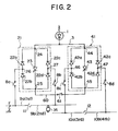
- Fig. 2 shows the first embodiment of the present invention, in which regenerative current is restored to only the electric car power supply lines.
- the installation comprises two diode bridge-connected circuits 21 and 41.
- the first diode bridge-connected circuit 21 includes a first pair of two series-connected diodes 22a and 22b and a second pair of two series-connected diodes 22c and 22d.
- the second diode bridge-connected circuit 41 includes a first pair of two series-connected diodes 42a and 42b and a second pair of two series-connected diodes 42c and 42d.
- the anode of the diode 22a is connected to the cathode of the diode 22b and similarly the anode of the diode 22c is connected to the cathode of the diode 22d.
- the cathodes of the diodes 22a and 22c are connected to a common junction point 24 connected to a powering bus bar 3, and the anodes of the diodes 22b and 22d are connected to another common junction point 25 connected to a mutual spare bus bar 60.
- the anode of a first thyristor breaker 23 (or a dc high speed breaker) is connected to the common junction point 24 of the first diode bridge-connected circuit 21, and the cathode of the breaker 23 is connected to the common junction point 25 of the first diode bridge-connected circuit 21.
- junction point 26 of the anode of the diode 22a and the cathode of the diode 22b is connected to a first electric car power supply line 9a through a dc disconnecting switch 8a, while a junction point 27 of the anode of the diode 22c and the cathode of the diode 22d is connected to a second electric car power supply line 9b through a dc disconnecting switch 8b.
- the second diode bridge-connected circuit 41 also includes a first pair of two series-connected diodes 42a and 42b and a second pair of two series-connected diodes 42c and 42d. Further, a second thyristor breaker 43 is connected in the second diode bridge-connected circuit 41.
- the diodes 42a, 42b, 42c and 42d of the second diode bridge-connected circuit 41 and the second thyristor breaker 43 are connected to each other in quite the same way as in the diodes 22a to 22d and the first breaker 23. Therefore, the description of the connections of these elements are omitted herein.
- junction point 46 of the anode of the diode 42a and the cathode of the diode 42b is connected to a third electric car power supply line 10a through a dc disconnecting switch 8c;
- a junction point 47 of the anode of the diode 42c and the cathode of the diode 42d is connected to a fourth electric car power supply line 10b through a dc disconnecting switch 8d.
- dc disconnecting switch 61 is connected midway of the mutual spare line 60 between the two junction points 25 and 45 of the two diode bridge-connected circuits 21 and 41. This dc disconnecting switch 61 is kept open under the normal conditions but closed in case either one of the first and second thyristor breakers 23 and 43 develops trouble. Further, in this embodiment, although the power rectifier 1 is shown by a diode rectifier, it is of course possible to configure the power rectifier 1 by plural thyristors.
- the two thyristor breakers 23 and 43 and the four dc disconnecting switches 8a to 8d are all kept closed, and the dc disconnecting switch 61 is kept opened. Therefore, a powering current of the power rectifier 1 is supplied to the first electric car power supply line 9a by way of the first thyristor breaker 23, the diode 22b and the dc disconnecting switch 8a and simultaneously to the second electric car power supply line 9b by way of the same first thyristor breaker 23, the diode 22d and the dc disconnecting switch 8b, that is, through the first thyristor breaker 23 and the first diode bridge-connected circuit 21.
- a powering current of the power rectifier 1 is supplied to the third electric car power supply line 10a by way of the second thyristor breaker 43, the diode 42b, and dc disconnecting switch 8c and to the fourth electric car power supply line 10b by way of the second thyristor breaker 43, the diode 42d and the dc disconnecting switch 8d, that is, through the second thyristor breaker 43 and the second diode bridge-connected circuit 41.
- a regenerative current generated by an electric car running on the first electric car power supply line 9a is restored to the second power supply line 9b by way of the dc disconnecting switch 8a, the diode 22a, the first thyristor breaker 23, the diode 22d, and the dc disconnecting switch 8b, to the third power supply line 10a by way of the dc disconnecting switch 8a, the diode 22a, the powering bus bar 3, the second thyristor breaker 43, the diode 42b, and the dc disconnecting switch 8c, or to the fourth power supply line 10b by way of the dc disconnecting switch 8a, the diode 22a, the powering bus bar 3, the second thyristor breaker 43, the diode 42d, and the dc disconnecting switch 8d.
- a regenerative current generated at the second, third and fourth power supply lines 9b, 10a, and 10b is supplied to the other power supply lines through either of the first and second thyristor breakers 23 and 43 and either of the first and second diode bridge circuits 21 and 41.
- the powering current is interrupted by opening the first thyristor breaker 23.
- the dc disconnecting switch 8a is opened and then the first thyristor breaker 23 is closed again.
- the regenerative current can be restored to the third and fourth power supply lines 10a and 10b through the routes as already described.
- the extension powering current can be interrupted to the first and second power supply lines 9a and 9b but supplied only to the third and fourth power supply lines 10a and 10b, therefore it is possible to smoothly drive electric cars running on the third and fourth power supply lines 10a and 10b.
- This simplies the operation sequence against accident, minimizes the harmful influence of an accident of a power supply line upon the other power supply line, and thus enhances the operation efficiency of the electric cars and the reliability of the system.
- the dc disconnecting switch 61 connected midway of the mutual spare bus bar 60 is closed. Under these conditions, it is possible to supply the power to the first and second power supply lines 9a and 9b connected to the defective thyristor breaker 23 from the second thyristor breaker 43 through the mutual spare bus bar 60. This enhances the reliability of the system.
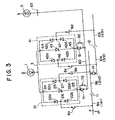
- Fig. 3 shows a second embodiment of the present invention, in which two stopper diodes 71 and 91 and a power inverter 2 are further provided in order to restore the regenerative power to a regenerative bus bar and further to the power supply bus bar through a power inverter, in addition to the functions of the installation described with reference to Fig. 2.
- the reference numerals 71 and 91 denote stopper diodes.
- the anode of the stopper diode 71 is connected to the common junction point 25 of the first diode bridge-connected circuit 21 and the anode of the stopper diode 91 is connected to the common junction point 45 of the second diode bridge-connected circuit 41.
- the cathodes of the two stopper diodes 71 and 91 are connected together to the mutual spare bus bar 60.
- This mutual spare bus bar 60 is connected to a power inverter 2 through a regenerative bus bar 63.
- the reference numeral 72 and 92 denote two dc disconnecting switches connected in parallel to each of the stopper diodes 71 and 92, separately. These two dc disconnecting switches 72 and 92 are kept open under the normal conditions but closed when either one of the thyristor breaker 23 or 43 develops trouble.
- a powering current is supplied to the first and second power supply lines 9a and 9b through the first thyristor breaker 23, the first diode bridge-connected circuit 21, and the dc disconnecting switch 8a or 8b, and to the third and fourth supply lines 10a and 10b through the second thyristor breaker 43, the second diode bridge-connected circuit 41 and the dc disconnecting switch 8c or 8d.
- a regenerative current generated at the first power supply line 9a is supplied to the second power supply line 9b by way of the dc disconnecting switch 8a, the diode 22a, the thyristor breaker 23, the diode 22d, and the dc disconnecting switch 8b, or to the third power supply line 10a by way of the dc disconnecting switch 8a, the diode 22a, the powering bus bar 3, the thyristor breaker 43, the diode 42b, and the dc disconnecting switch 8c, or to the fourth power supply line 10b by way of the dc disconnecting switch 8a, the diode 22a, the powering bus bar 3, the thyristor breaker 43, the diode 42d, and the dc disconnecting switch 8d, or additionally to the regenerative bus bar 63 by way of the dc disconnecting switch 8a, the diode 22a, the first thyristor breaker 23, the stopper diode 71 or the dc disconnecting switch
- regenerative currents generated at the other second, third, and fourth power supply lines 9b, 10a and 10b are restored to each of the other power supply lines or the regenerative bus bar 63 through the first or second diode bridge-connected circuit 21 or 41 or the stopper diode 71 or 91 or the dc disconnecting switch 72 or 92, respectively.
- the first thyristor breaker 23 is opened to interrupt the powering current. Therefore, the dc disconnecting switch 8a is opened and further the first thyristor breaker 23 is closed again. Under these conditions, even if a regenerative electric car 14 is running on the second power supply line 9b, its regenerative current is restored to the regenerative bus bar 63 or the third and fourth power supply lines 10a and 10b through the routes already described.
- the dc disconnecting switches 72 and 92 are both closed to mutually supply the power between the first and second diode bridge-connected circuits 21 and 41, because the installation is of mutual spare bus bar type. That is, in case the first thyristor breaker 23 develops trouble, the powering current can be supplied to the first and second power supply lines 9a and 9b by way of the second thyristor breaker 43, the stopper diode 91, the mutual spare bus bar 60, the dc disconnecting switch 72, the diode 22b or 22d and the dc disconnecting switch 8a or 8b. Further, the regenerative current from the first and second power supply lines 9a and 9b can be restored to the regenerative bus bar 63.
- Fig. 4 shows a third embodiment of the present invention in which a two-way power converter is connected in place of the power inverter 2 shown in Fig. 3 and a diode series-connected circuit is further provided in order to enhance the reliability of the installation.
- the reference numeral 101 denotes a diode series-connected circuit including two diodes 102 and 103.
- the anode of the diode 102 is connected to the cathode of the two stopper diodes 71 and 91 through the mutual spare bus bar 60.
- the cathode of the diode 103 is connected to the power rectifier 1 through the powering bus bar 3.
- the regenerative bus bar 63 is connected to a common junction point 104 between the two diodes 102 and 103.
- a two-way power converter 100 for converting an ac power current to a dc power current or vice versa is connected to the regenerative bus bar 63.
- the two-way power converter 100 When the two-way power converter 100 is operated as a spare power rectifier in addition to the power rectifier 1, it is possible to reduce the capacity of the power rectifier 1. Further, in case the power rectifier 1 develops trouble, it is possible to supply a powering current to all the electrtic car power supply lines 9a, 9b, 10a and 10b through the first and second diode bridge-connected circuits 21 and 41 and the first and second thyristor breakers 23 and 43 without suspending the substation.
- the two-way power converter 100 when the two-way power converter 100 is operated as a power inverter, it is possible to pass a regenerative current to the powering bus bar 3 through the two diodes 102 and 103. Therefore, in case the two-way power converter 100 fails in commutation during power inverter operation, it is possible to prevent the regenerative current from flowing to the side of the two-way power converter 100, that is, to prevent the spread of an accident due to commutation failure of the power inverter 100.
- the two-way power converter 100 when operated as a power inverter and fails in commutation, it is possible to interrupt an accident current flowing from the power rectifier 1 to the two-way power converter 100 or to prevent a regenerative current from flowing to the two-way power converter 100. That is, the spread of an accident of the two-way power converter can be prevented.
Landscapes
- Engineering & Computer Science (AREA)
- Mechanical Engineering (AREA)
- Life Sciences & Earth Sciences (AREA)
- Chemical & Material Sciences (AREA)
- Combustion & Propulsion (AREA)
- Transportation (AREA)
- Wood Science & Technology (AREA)
- Forests & Forestry (AREA)
- General Engineering & Computer Science (AREA)
- Inorganic Chemistry (AREA)
- Automation & Control Theory (AREA)
- Power Engineering (AREA)
- Dispersion Chemistry (AREA)
- Manufacturing & Machinery (AREA)
- Microelectronics & Electronic Packaging (AREA)
- Chemical Kinetics & Catalysis (AREA)
- Electrochemistry (AREA)
- General Chemical & Material Sciences (AREA)
- Electric Propulsion And Braking For Vehicles (AREA)
- Direct Current Feeding And Distribution (AREA)
- Rectifiers (AREA)
Abstract
Description
- The present invention relates generally to a power supply installation for a direct current (dc) electric railroad and more specifically to a power supply installation by which an alternating current (ac) power is converted into a dc current power before being supplied to electric cars as a powering source.
- Usually, a plurality of dc substantions are installed at appropriate intervals along a railroad track. In these dc substations, a single or plural sets of converters are arranged. The dc power output side of the converter is connected to each of electric car power supply lines through each semiconductor breaker and the ac power input side thereof is directly connected in common with a power conductor. In other words, plural power supply circuits having power rectifiers and high-speed dc breakers are connected in parallel with each other between substations so as to constract a dc power supply installation.
- On the other hand, the electric car power supply lines are divided into plural sections, and each of the above divided electric car power supply line is connected to a positive bus bar through a high-speed breaker provided for each electric car power supply line and the electric car rails are connected to a negative bus bar at each substation.
- In the prior art power supply installation for a dc railroad, however, there exist various drawbacks as follows: (1) In case the power rectifier fails in commutation, the influence of an accident due to the commutation failure tends to spread. (2) Once the regenerative breaker is turned off, the power is suspended for all the adjacent power supply lines. (3) The interruption capacity of the regenerative breaker should be great because the regenerative current and plural extension power supply currents should be interrupted. (4) To reduce the interruption capacity of the regenerative breaker, it is necessary to interrupt the extension powering current at the adjacent substation. This operation complicates the operation sequence against accident and therefore lowers the reliability of the installation. (5) In the case of a double track, since four powering breakers should be provided, the installation is costly.
- The arrangement of the prior art power supply installation for a direct current railroad will be described in further detail hereinafter with reference to Fig. 1 under DETAILED DESCRIPTION OF THE PREFERRED EMBODIMENTS.
- With these problems in mind, therefore, it is the primary object of the present invention to provide a novel power supply installation for a direct current railroad which can prevent the harmful influence of an accident or a trouble from being exerted upon other sections of the installation or' upon the adjacent substation in order to keep the service of electric cars as widely as possible while reducing the cost of the power supply installation.
- To achieve the above-mentioned object, the power supply installation for a direct current railroad according to the present invention for supplying a direct current power to at least two first and second electric car power supply lines (in a single track) arranged in series via a dead section comprises: (a) a power rectifier for converting an alternating current power to a direct current power in powering operation; (b) a first diode bridge-connected circuit having common-connected cathodes connected to said power rectifier; (c) a first breaker connected between the common-connected cathodes and common-connected anodes of the first diode bridge-connected circuit, for simultaneously controlling a connection and a disconnection of a powering current supplied from said power rectifier to the two electric car power supply lines and a regenerative current supplied from one of the two power supply lines to the other thereof; (d) a first dc disconnecting switch connected between a first intermediate point of said first diode bridge-connected circuit and the first electric car power supply line, for disconnecting a powering current from said power rectifier in case an accident occurs at the first power supply line; and (e) a second dc disconnecting switch connected between a second intermediate point of said first diode bridge-connected circuit and the second electric car power supply line, for disconnecting a powering current from said power rectifier in case an accident occurs at the second power supply line.
- In the case of a double track, the power supply installation according to the present invention further comprises: (a) a second diode bridge-connected circuit having common-connected cathodes connected to said power rectifier in parallel with said first diode bridge-connected circuit; (b) a second breaker connected between the common-connected cathodes and common-connected anodes of said second diode bridge-connected circuit, for simultaneously controlling a connection and a disconnection of a powering current supplied from said power rectifier to a third and fourth electric car power supply lines arranged in series via a dead section and in parallel with the first and second power supply lines, respectively, and a regenerative current supplied from one of the third and fourth power supply lines to the other power supply lines; (c) a third dc disconnecting switch connected between a first intermediate point of said second diode bridge-connected circuit and the third electric car power supply line, for disconnecting a powering current from said power rectifier in case an accident occurs at the third power supply line; (d) a fourth dc disconnecting switch connected between a second intermediate point of said second diode bridge-connected circuit and the fourth electric car power supply line, for disconnecting a powering current from said power rectifier in case an accident occurs at the fourth power supply line; and (e) a fifth dc disconnecting switch connected between common-connected anodes of said first diode bridge-connected circuit and common-connected anodes of said second diode bridge-connected circuit, said fifth dc disconnecting switch being usually opened but closed only when either one of said first and second breakers is defective.
- In this first embodiment for a single track, a regenerative current generated at an electric car power supply line can be restored to the other electric car power supply lines.
- In the above installation, in case either one of the breakers is broken down, the fifth dc disconnecting switch is closed in the mutual spare bus bar to connect the two diode bridge-connected circuits. Therefore, it is possible to keep the power supply to all the electric car power supply line.
- In case a ground fault occurs at an electric car power supply line, only the dc disconnecting switch connected to the ground fault power supply line is opened. Therefore, it is possible to keep the power supply to the other power supply lines except the ground fault line. In this case, the extension powering current supplied from the adjacent substation can also be interrupted by the opened dc disconnecting switch.
- In the case where only one track is required to be power-suspended, only the thyristor breaker connected to the track is opened with the other thyristor breaker is kept closed. Therefore, it is possible to supply an extension powering current only to the other track without supplying an extension powering current to the power-suspended track.
- Further, in case an accident occurs during an extension power supply operation, only the thyristor breaker connected to a defective electric car power supply line is opened. In this case, since the extension powering current is interrupted simultaneously, it is unnecessary to interrupt the extension powering current at the adjacent substation.
- In the second embodiment of the present invention, two stopper diodes and two dc disconnecting switches connected in parallel to the two stopper diodes are connected between the two diode bridge-connected circuits and the mutual spare bus bar, respectively. Therefore, a regenerative current generated at an electric car power supply line can also be restored to the power supply bus bar through a power inverter.
- In the third embodiment of the present invention, a diode series-connected circuit is connected between the powering bus bar and the regenerative bus bar, and a two-way power converter is connected to the diode series-connected circuit, in order to further enhance the reliability of the installation.
- The features and advantages of the power supply installation for a dc railroad according to the present invention over the prior art power supply installation will be more clearly appreciated from the following description of the preferred embodiment of the invention taken in conjunction with the accompanying drawings in which like reference numerals designate the same or similar elements or sections and in which:
- Fig. 1 is a scehmatic block diagram of the prior art power supply installation for a dc railroad;
- Fig. 2 is a schematic block diagram of the first embodiment of the power supply installation for a dc railroad according to the present invention;
- Fig. 3 is a schematic block diagram of the second embodiment of the power supply installation for a dc railroad according to the present invention; and
- Fig. 4 is a scehmatic block diagram of the third embodiment of the power supply installation for a dc railroad according to the present invention.
- To facilitate understanding of the present invention, a brief reference will be made to a prior art power supply installation for a dc electric railroad with reference to the attached drawing.
- Fig. 1 shows a prior art power supply installation for a double-track railroad installed in each substation. In the drawing, the reference numeral 1 denotes a power rectifier made up of plural thyristors for converting an ac power to a dc power; the
reference numeral 2 denotes a power inverter made up of plural thyristors for converting a dc power to an ac power. Thereference numeral 3 denotes a dc bus bar for directly connecting the power rectifier 1 to thepower inverter 2. Further, thereference numeral 4a to 4d denote powering thyristor breakers (referred to as powering breakers; thenumeral 6 denotes a regenerative thyristor breaker (referred to as a regenerative breaker); thenumerals 5a to 5d denote regenerative diodes. The anodes of theseregenerative diodes 5a to 5d are connectred to the cathode of each of thepowering breakers 4a to 4d separately, and the cathodes of theseregenerative diodes 5a to 5d are connected together to the anode of theregenerative breaker 6. Further, the cathode of theregenerative breaker 6 is connected to thedc bus bar 3 which connects the power rectifier 1 to thepower inverter 2. Thereference numeral 8a to 8d denote dc disconnecting switches; thenumeral numeral power supply lines dead section 11 and the third and fourth electric carpower supply lines power supply lines power supply lines - Therefore, power is simultaneously supplied to each electric car power supply line from both the substation and the adjacent substation (not shown). Further, power is supplied to one electric car power supply line (e.g. 9a) from the other electric power supply line (e.g. lOb) through the power supply installation (e.g. the
dc disconnecting switch 8d, theregenerative diode 5d, theregenerative breaker 6,dc bus bar 3, thepowering breaker 4a, and thedc disconnecting switch 8a, in case the power rectifier 1 is defective. The above power supplying system is referred to as an extension power supply system. - The prior art installation shown in Fig. 1 operates as follows: In order to supply an electric car driving power to electric cars, a three-phase ac voltage received from a commercial frequency 3-phase ac transmission line (not shown) through an ac circuit breaker (not shown) is dropped to an appropriate voltage through a transformer (not shown) arranged in the substation, converted into a dc power through the power rectifier 1, and then supplied to an
electric car 13 running on the fourth electric carpower supply line 10b, for instance, through the poweringbreaker 4d and thedc disconnecting switch 8d. - When an
electric car 13, for instance, is in regenerative braking operation, the regenerative power is restored from the fourth electric carpower supply line 10b to thedc bus bar 3 through thedc disconnecting switch 8d, theregenerative diode 5d and theregenerative breaker 6. The restored regenerative power of thedc bus bar 3 is supplied to a powering electric car (not shown) running on any one of thepower supply lines power inverter 2. - The above-mentioned prior art power supply installation for a dc railroad involves various problems as follows:
- (1) Since the power rectifier 1 and the
power inverter 2 are directly connected to each other by thedc bus bar 3 in reverse parallel relationship, in case thepower inverter 2 fails in commutation, a large accident current flows from the power rectifier 1 to the power supply bus bar through thepower inverter 2, thus there exists a problem in that an accident due to commutation failure of thepower inverter 2 spreads wider. - (2) In the case where only the disconnecting
switch 8a is required to open for maintenance, for instance, this disconnectingswitch 8a should be opened after the poweringbreaker 4a has been turned off for safety. Further, when an electric car in regenerative breaking operation is running on the first electric carpower supply line 9a, theregenerative breaker 6 should also be turned off before opening thedc disconnecting switch 8a. Once theregenerative breaker 6 is opened, the following problems arise. - (a) Since the regenerative current cannot be restored through the
regenerative breaker 6 and further the extension powering currents are all interrupted, even when power suspension is required for a desired power supply section, the power supply to the other adjoining electric car power supply lines should be suspended simultaneously, so that many electric cars are tied up. - (b) In case of an accident, when only the
regenerative breaker 6 is used for interrupting regenerative currents and extension power supply currents supplied from the other adjacent substations, the interruption capability of theregenerative breaker 6 should at least be four times greater than that of thepowering breaker - (c) In order to reduce the interruption capacity of the
regenerative breaker 6 to such a small extent as to be able to interrupt only the regenerative current, it is impossible to interrupt the extension power supply currents by theregenerative breaker 6 when a regenerative car is running on any of the four power supply lines during an accident. Therefore, it is necessary to interrupt an extension current flowing to an accident point at the adjacent substation, so that the operation sequence against an accident is complicated and the reliability of the system is thus deteriorated. - (d) In the case of the double track, since four powering
breakers 4a to 4d are necessary, the substation is costly. - In view of the above description, reference is now made to embodiments of the power supply installation for a dc railroad according to the present invention applied to a double-track railroad, by way of example, with reference to the attached drawings.
- In the drawings, the same reference numerals have been retained for similar parts or sections which have the same functions as is the case with the prior art installation previously described with reference to Fig. 1, and any detailed description of them is believed to be unnecessary.
- Fig. 2 shows the first embodiment of the present invention, in which regenerative current is restored to only the electric car power supply lines. Being different from the prior art installation shown in Fig. 1, the installation comprises two diode bridge-connected
circuits circuit 21 includes a first pair of two series-connecteddiodes diodes circuit 41 includes a first pair of two series-connecteddiodes diodes - The anode of the
diode 22a is connected to the cathode of thediode 22b and similarly the anode of thediode 22c is connected to the cathode of thediode 22d. The cathodes of thediodes common junction point 24 connected to a poweringbus bar 3, and the anodes of thediodes common junction point 25 connected to a mutualspare bus bar 60. - The anode of a first thyristor breaker 23 (or a dc high speed breaker) is connected to the
common junction point 24 of the first diode bridge-connectedcircuit 21, and the cathode of thebreaker 23 is connected to thecommon junction point 25 of the first diode bridge-connectedcircuit 21. - Further, a
junction point 26 of the anode of thediode 22a and the cathode of thediode 22b is connected to a first electric carpower supply line 9a through adc disconnecting switch 8a, while ajunction point 27 of the anode of thediode 22c and the cathode of thediode 22d is connected to a second electric carpower supply line 9b through adc disconnecting switch 8b. - The second diode bridge-connected
circuit 41 also includes a first pair of two series-connecteddiodes diodes second thyristor breaker 43 is connected in the second diode bridge-connectedcircuit 41. Thediodes circuit 41 and thesecond thyristor breaker 43 are connected to each other in quite the same way as in thediodes 22a to 22d and thefirst breaker 23. Therefore, the description of the connections of these elements are omitted herein. However, ajunction point 46 of the anode of thediode 42a and the cathode of thediode 42b is connected to a third electric carpower supply line 10a through adc disconnecting switch 8c; ajunction point 47 of the anode of thediode 42c and the cathode of thediode 42d is connected to a fourth electric carpower supply line 10b through adc disconnecting switch 8d. - Further, another
dc disconnecting switch 61 is connected midway of the mutualspare line 60 between the twojunction points circuits dc disconnecting switch 61 is kept open under the normal conditions but closed in case either one of the first andsecond thyristor breakers - The operation of the first embodiment will be described hereinbelow. Under the normal conditions, the two
thyristor breakers dc disconnecting switch 61 is kept opened. Therefore, a powering current of the power rectifier 1 is supplied to the first electric carpower supply line 9a by way of thefirst thyristor breaker 23, thediode 22b and thedc disconnecting switch 8a and simultaneously to the second electric carpower supply line 9b by way of the samefirst thyristor breaker 23, thediode 22d and thedc disconnecting switch 8b, that is, through thefirst thyristor breaker 23 and the first diode bridge-connectedcircuit 21. Similarly, a powering current of the power rectifier 1 is supplied to the third electric carpower supply line 10a by way of thesecond thyristor breaker 43, thediode 42b, anddc disconnecting switch 8c and to the fourth electric carpower supply line 10b by way of thesecond thyristor breaker 43, thediode 42d and thedc disconnecting switch 8d, that is, through thesecond thyristor breaker 43 and the second diode bridge-connectedcircuit 41. - Further, a regenerative current generated by an electric car running on the first electric car
power supply line 9a is restored to the secondpower supply line 9b by way of thedc disconnecting switch 8a, thediode 22a, thefirst thyristor breaker 23, thediode 22d, and thedc disconnecting switch 8b, to the thirdpower supply line 10a by way of thedc disconnecting switch 8a, thediode 22a, the poweringbus bar 3, thesecond thyristor breaker 43, thediode 42b, and thedc disconnecting switch 8c, or to the fourthpower supply line 10b by way of thedc disconnecting switch 8a, thediode 22a, the poweringbus bar 3, thesecond thyristor breaker 43, thediode 42d, and thedc disconnecting switch 8d. - In the same way, a regenerative current generated at the second, third and fourth
power supply lines second thyristor breakers diode bridge circuits - In the above-mentioned operation, it should be noted that only two powering
breakers power supply lines breakers 4a to 4d are connected to supply powering currents. Since the thyristor breaker is high costly, it is possible to reduce the cost of the installation in the present embodiment. Further, since the powering current and the regenerative current both flow through the first andsecond thyristor breakers breakers - For instance, in case a ground fault occurs at point F on the first electric car
power supply line 9a, the powering current is interrupted by opening thefirst thyristor breaker 23. Consecutively, thedc disconnecting switch 8a is opened and then thefirst thyristor breaker 23 is closed again. Under these conditions, even when a regenerativeelectric car 14 is running on the secondpower supply line 9b, the regenerative current can be restored to the third and fourthpower supply lines - Further, in the case where only the single track, (the first and the second electric car
power supply lines first thyristor breaker 23 is opened with thesecond thyristor breaker 43 kept closed. In this case, since the extension powering current can be interrupted to the first and secondpower supply lines power supply lines power supply lines - Further, in case an accident occurs during an extension power supply operation, only the
thyristor breaker power supply line 9a, thefirst thyristor breaker 23 is opened, so that the powering current is of course interrupted. In this case, although another extension powering current is supplied to the firstpower supply line 9a from the adjacent substation through the secondpower supply line 9b, since this extension powering current is blocked by thediodes first thyristor breaker 23. Therefore, it is unnecessary to interrupt the extension powering current supplied from the adjacent substation to the firstpower supply line 9a via the secondpower supply line 9b at the adjacent substation. - This simplies the operation sequence against accident, minimizes the harmful influence of an accident of a power supply line upon the other power supply line, and thus enhances the operation efficiency of the electric cars and the reliability of the system.
- Furthermore, in case the
first thyristor breaker 23 is broken down, for instance, thedc disconnecting switch 61 connected midway of the mutualspare bus bar 60 is closed. Under these conditions, it is possible to supply the power to the first and secondpower supply lines defective thyristor breaker 23 from thesecond thyristor breaker 43 through the mutualspare bus bar 60. This enhances the reliability of the system. - Fig. 3 shows a second embodiment of the present invention, in which two
stopper diodes power inverter 2 are further provided in order to restore the regenerative power to a regenerative bus bar and further to the power supply bus bar through a power inverter, in addition to the functions of the installation described with reference to Fig. 2. - In Fig. 3, the
reference numerals stopper diode 71 is connected to thecommon junction point 25 of the first diode bridge-connectedcircuit 21 and the anode of thestopper diode 91 is connected to thecommon junction point 45 of the second diode bridge-connectedcircuit 41. The cathodes of the twostopper diodes spare bus bar 60. This mutualspare bus bar 60 is connected to apower inverter 2 through aregenerative bus bar 63. Thereference numeral stopper diodes thyristor breaker - The operation of the second embodiment shown in Fig. 3 will be described hereinbelow. In the same way as in the first embodiment, a powering current is supplied to the first and second
power supply lines first thyristor breaker 23, the first diode bridge-connectedcircuit 21, and thedc disconnecting switch fourth supply lines second thyristor breaker 43, the second diode bridge-connectedcircuit 41 and thedc disconnecting switch - A regenerative current generated at the first
power supply line 9a is supplied to the secondpower supply line 9b by way of thedc disconnecting switch 8a, thediode 22a, thethyristor breaker 23, thediode 22d, and thedc disconnecting switch 8b, or to the thirdpower supply line 10a by way of thedc disconnecting switch 8a, thediode 22a, the poweringbus bar 3, thethyristor breaker 43, thediode 42b, and thedc disconnecting switch 8c, or to the fourthpower supply line 10b by way of thedc disconnecting switch 8a, thediode 22a, the poweringbus bar 3, thethyristor breaker 43, thediode 42d, and thedc disconnecting switch 8d, or additionally to theregenerative bus bar 63 by way of thedc disconnecting switch 8a, thediode 22a, thefirst thyristor breaker 23, thestopper diode 71 or thedc disconnecting switch 72 when closed, the mutualspare bus bar 60 or by way of the disconnectingswitch 8a, thediode 22a, the poweringbus bar 3, thesecond thyristor breaker 43, and thestopper diode 91 or thedc disconnecting switch 92 when closed. Further, regenerative currents generated at the other second, third, and fourthpower supply lines regenerative bus bar 63 through the first or second diode bridge-connectedcircuit stopper diode dc disconnecting switch - In this second embodiment, it should be noted that it is possible to eliminate the use of the
regenerative breaker 6 required for the prior art installation shown in Fig. 1. - In the same way as in the first embodiment, since the powering current and the regenerative current both flow through the first and
second thyristor breakers breakers - Further, in case a ground fault accident occurs at point F of the first
power supply line 9a, thefirst thyristor breaker 23 is opened to interrupt the powering current. Therefore, thedc disconnecting switch 8a is opened and further thefirst thyristor breaker 23 is closed again. Under these conditions, even if a regenerativeelectric car 14 is running on the secondpower supply line 9b, its regenerative current is restored to theregenerative bus bar 63 or the third and fourthpower supply lines circuits stopper diodes 71 and 91 (when the dc disconnecting switches 30 and 31 are kept open) and the mutualspare bus bar 60, once thefirst thyristor breaker 23 is opened, an accident current will not flow through thesecond thyristor breaker 43 to the firstpower supply line 9a (because thestopper diode 71 is connected in the reverse direction), so that it is possible to prevent the spread of the accident at point F. - In the extension power supply operation such that the first and second diode bridge-connected
circuits second thyristor breakers power supply lines first thyristor breaker 23 is opened. Therefore, it is possible to supply the power to the other third and fourthpower supply lines thyristor breakers - Further, in case either one of the first and
second thyristor breakers circuits first thyristor breaker 23 develops trouble, the powering current can be supplied to the first and secondpower supply lines second thyristor breaker 43, thestopper diode 91, the mutualspare bus bar 60, thedc disconnecting switch 72, thediode dc disconnecting switch power supply lines regenerative bus bar 63. - Fig. 4 shows a third embodiment of the present invention in which a two-way power converter is connected in place of the
power inverter 2 shown in Fig. 3 and a diode series-connected circuit is further provided in order to enhance the reliability of the installation. - In Fig. 4, the
reference numeral 101 denotes a diode series-connected circuit including twodiodes diode 102 is connected to the cathode of the twostopper diodes spare bus bar 60. The cathode of thediode 103 is connected to the power rectifier 1 through the poweringbus bar 3. Further, theregenerative bus bar 63 is connected to acommon junction point 104 between the twodiodes way power converter 100 for converting an ac power current to a dc power current or vice versa is connected to theregenerative bus bar 63. - Only the operation of the third embodiment different from that of the second embodiment shown in Fig. 3 will be described hereinbelow.
- When the two-
way power converter 100 is operated as a spare power rectifier in addition to the power rectifier 1, it is possible to reduce the capacity of the power rectifier 1. Further, in case the power rectifier 1 develops trouble, it is possible to supply a powering current to all the electrtic carpower supply lines circuits second thyristor breakers - Further, when the two-
way power converter 100 is operated as a power inverter, it is possible to pass a regenerative current to the poweringbus bar 3 through the twodiodes way power converter 100 fails in commutation during power inverter operation, it is possible to prevent the regenerative current from flowing to the side of the two-way power converter 100, that is, to prevent the spread of an accident due to commutation failure of thepower inverter 100. - As described above, in the power supply installation for a dc railroad according to the present invention, there exist various advantages as follows:
- (a) Since both the powering and regenerative currents can be controlled by only two
thyristor breakers - (b) Since the installation is of mutual spare power supply type, even if either one of the two
thyristor breakers - (c) Since a
dc disconnecting switch 61 or twostopper diodes stopper diodes - (d) When one of a double track is required to suspend the powering current during an extension power supply operation, one of the
thyristor breakers - (e) In case an accident occurs during an extension powder supply operation, since an extension power supply current supplied from an adjacent substation can be interrupted by the thyristor breaker connected to an accient power supply line, it is unnecessary to interrupt the extension powering current at the adjacent substation. Therefore, it is possible to simplify the operation sequence of repair or maintenance and further to minimize the influence of an accident upon other substations.
- (f) Further, in the case of the third embodiment shown in Fig. 4, since a two-
way power converter 100 and a diode series-connectedcircuit 101 are additionally connected and can be operated as a power rectifier, it is possible to reduce the capacity of the power rectifier 1 or to supply a powering current in case the power rectifier 1 develops trouble, without suspending the substation. - Further, when the two-
way power converter 100 is operated as a power inverter and fails in commutation, it is possible to interrupt an accident current flowing from the power rectifier 1 to the two-way power converter 100 or to prevent a regenerative current from flowing to the two-way power converter 100. That is, the spread of an accident of the two-way power converter can be prevented. - Further, in case an accident occurs at an electric car power supply line when a powering current is supplied during the mutual spare power supply operation and further the two-
way power converter 100 is operating as a power rectifier, it is possible to prevent a powering current from directly flowing from the two-way power converter to a defective power supply line only by opening a thyristor breaker connected to the defective power supply line. - (g) In summary, the features and advantages of the installation according to the present invention is such that in case an accident occurs, it is possible to effectively prevent the spread of an accident and thus enhance the reliability of the system, in spite of the fact that the number of thyristor breakers is reduced into only two.
Claims (9)
Applications Claiming Priority (6)
| Application Number | Priority Date | Filing Date | Title |
|---|---|---|---|
| JP60153698A JPS6215140A (en) | 1985-07-12 | 1985-07-12 | Direct current feeding device |
| JP153698/85 | 1985-07-12 | ||
| JP15870585A JPH0688512B2 (en) | 1985-07-18 | 1985-07-18 | DC power supply |
| JP158705/85 | 1985-07-18 | ||
| JP60158699A JPS6218339A (en) | 1985-07-18 | 1985-07-18 | Direct current feeding device |
| JP158699/85 | 1985-07-18 |
Publications (3)
| Publication Number | Publication Date |
|---|---|
| EP0209087A2 true EP0209087A2 (en) | 1987-01-21 |
| EP0209087A3 EP0209087A3 (en) | 1988-02-10 |
| EP0209087B1 EP0209087B1 (en) | 1993-04-28 |
Family
ID=27320516
Family Applications (1)
| Application Number | Title | Priority Date | Filing Date |
|---|---|---|---|
| EP86109492A Expired - Lifetime EP0209087B1 (en) | 1985-07-12 | 1986-07-11 | Power supply installation for dc electric railroad |
Country Status (6)
| Country | Link |
|---|---|
| US (1) | US4731723A (en) |
| EP (1) | EP0209087B1 (en) |
| KR (1) | KR960001555B1 (en) |
| CN (1) | CN1007507B (en) |
| DE (1) | DE3688347T2 (en) |
| HK (1) | HK142393A (en) |
Cited By (3)
| Publication number | Priority date | Publication date | Assignee | Title |
|---|---|---|---|---|
| DE4104384A1 (en) * | 1991-02-11 | 1992-08-13 | Elpro Ag | METHOD AND CIRCUIT ARRANGEMENT FOR OPERATING A RECTIFIER BASE |
| DE4106054A1 (en) * | 1991-02-22 | 1992-08-27 | Elpro Ag | DC power supply circuitry for electrically powered vehicles - has thyristor rectifier and switching stages coupled to distributed sections of overhead conductor |
| WO1993002890A1 (en) * | 1991-08-09 | 1993-02-18 | Elpro Ag Berlin-Industrieelektronik Und Anlagenbau- | Circuitry for rectifier substations |
Families Citing this family (8)
| Publication number | Priority date | Publication date | Assignee | Title |
|---|---|---|---|---|
| DE3941885A1 (en) * | 1989-12-19 | 1991-06-20 | Philips Patentverwaltung | POWER SUPPLY DEVICE WITH UNBALANCED MONITORING CIRCUIT |
| US5280418A (en) * | 1990-11-11 | 1994-01-18 | Griffin Anthony J | Voltage regulation in a railway power distribution system |
| AU2432701A (en) * | 1999-12-16 | 2001-06-25 | Mcandrews Enterprises Inc. | Spare bus power plant |
| US7277782B2 (en) * | 2001-01-31 | 2007-10-02 | Oshkosh Truck Corporation | Control system and method for electric vehicle |
| AT500328B1 (en) | 2002-02-07 | 2010-03-15 | Elin Ebg Traction Gmbh | VEHICLE WITH AN ELECTRIC DRIVE AND METHOD FOR OPERATING SUCH A VEHICLE |
| JP4848729B2 (en) * | 2005-10-12 | 2011-12-28 | 株式会社明電舎 | DC electric railway power storage device |
| TWI339930B (en) * | 2007-03-28 | 2011-04-01 | Delta Electronics Inc | Energy recycle system for use with ac current power supply |
| WO2021127760A1 (en) * | 2019-12-27 | 2021-07-01 | Aerom Sistemas De Transporte Sa | Section isolation valve for pneumatic transport system |
Family Cites Families (4)
| Publication number | Priority date | Publication date | Assignee | Title |
|---|---|---|---|---|
| DE1956527C3 (en) * | 1969-11-11 | 1973-01-04 | Siemens Ag, 1000 Berlin U. 8000 Muenchen | Differential protection device |
| FR2474784A1 (en) * | 1979-12-20 | 1981-07-31 | Alsthom Atlantique | ELECTRONIC DEVICE FOR CONTROLLING A CONTINUOUS CURRENT MACHINE WITH A SEPARATE EXCITATION |
| US4480298A (en) * | 1983-01-25 | 1984-10-30 | Westinghouse Electric Corp. | Multiple output DC-to-DC voltage converter apparatus |
| US4600982A (en) * | 1984-02-22 | 1986-07-15 | Rolm Corporation | Low power consuming AC to DC converter |
-
1986
- 1986-07-10 US US06/883,998 patent/US4731723A/en not_active Expired - Fee Related
- 1986-07-11 EP EP86109492A patent/EP0209087B1/en not_active Expired - Lifetime
- 1986-07-11 KR KR1019860005593A patent/KR960001555B1/en not_active Expired - Fee Related
- 1986-07-11 DE DE8686109492T patent/DE3688347T2/en not_active Expired - Fee Related
- 1986-07-12 CN CN86101664A patent/CN1007507B/en not_active Expired
-
1993
- 1993-12-30 HK HK1423/93A patent/HK142393A/en unknown
Cited By (4)
| Publication number | Priority date | Publication date | Assignee | Title |
|---|---|---|---|---|
| DE4104384A1 (en) * | 1991-02-11 | 1992-08-13 | Elpro Ag | METHOD AND CIRCUIT ARRANGEMENT FOR OPERATING A RECTIFIER BASE |
| WO1992013735A1 (en) * | 1991-02-11 | 1992-08-20 | Elpro Aktiengesellschaft Berlin | Rectifier sub-station circuit for a railway d.c. power supply, and method of providing such a supply |
| DE4106054A1 (en) * | 1991-02-22 | 1992-08-27 | Elpro Ag | DC power supply circuitry for electrically powered vehicles - has thyristor rectifier and switching stages coupled to distributed sections of overhead conductor |
| WO1993002890A1 (en) * | 1991-08-09 | 1993-02-18 | Elpro Ag Berlin-Industrieelektronik Und Anlagenbau- | Circuitry for rectifier substations |
Also Published As
| Publication number | Publication date |
|---|---|
| HK142393A (en) | 1994-01-07 |
| US4731723A (en) | 1988-03-15 |
| KR960001555B1 (en) | 1996-02-02 |
| KR870001699A (en) | 1987-03-17 |
| DE3688347T2 (en) | 1993-08-05 |
| EP0209087A3 (en) | 1988-02-10 |
| DE3688347D1 (en) | 1993-06-03 |
| CN1007507B (en) | 1990-04-11 |
| CN86104573A (en) | 1987-01-14 |
| EP0209087B1 (en) | 1993-04-28 |
Similar Documents
| Publication | Publication Date | Title |
|---|---|---|
| EP0206150B1 (en) | Power supply installation for dc electric railroad | |
| US4731723A (en) | Power supply installation for DC electric railroad | |
| JPS6218338A (en) | Direct current feeding device | |
| JPH0688513B2 (en) | DC power supply | |
| JPH0688510B2 (en) | DC power supply | |
| JPS62214030A (en) | D.c. feeder | |
| JPH07110591B2 (en) | DC power supply | |
| JPS62205835A (en) | Direct current load dispatching device | |
| JPH0688511B2 (en) | DC power supply | |
| JPH07110590B2 (en) | DC power supply | |
| JPS6220735A (en) | Dc power feeding device | |
| JPS6218340A (en) | Direct current feeding device | |
| JPS6218343A (en) | Direct current feeding device | |
| JPS62214028A (en) | D.c. feeder | |
| JPH0688512B2 (en) | DC power supply | |
| JPS62210141A (en) | Dc feeding system | |
| JPS6215140A (en) | Direct current feeding device | |
| JPS63188540A (en) | Direct current feeder | |
| JPS62205834A (en) | Direct current load dispatching device | |
| JPS6215138A (en) | Direct current supply system | |
| JPS62214029A (en) | D.c. feeder | |
| JPS6218344A (en) | Direct current feeding device | |
| JPS62210140A (en) | Dc feeding system | |
| JPH0688507B2 (en) | DC power supply | |
| JPS6220732A (en) | Dc power feeding device |
Legal Events
| Date | Code | Title | Description |
|---|---|---|---|
| PUAI | Public reference made under article 153(3) epc to a published international application that has entered the european phase |
Free format text: ORIGINAL CODE: 0009012 |
|
| AK | Designated contracting states |
Kind code of ref document: A2 Designated state(s): DE FR GB |
|
| PUAL | Search report despatched |
Free format text: ORIGINAL CODE: 0009013 |
|
| AK | Designated contracting states |
Kind code of ref document: A3 Designated state(s): DE FR GB |
|
| 17P | Request for examination filed |
Effective date: 19880722 |
|
| 17Q | First examination report despatched |
Effective date: 19900627 |
|
| GRAA | (expected) grant |
Free format text: ORIGINAL CODE: 0009210 |
|
| AK | Designated contracting states |
Kind code of ref document: B1 Designated state(s): DE FR GB |
|
| REF | Corresponds to: |
Ref document number: 3688347 Country of ref document: DE Date of ref document: 19930603 |
|
| ET | Fr: translation filed | ||
| PLBE | No opposition filed within time limit |
Free format text: ORIGINAL CODE: 0009261 |
|
| STAA | Information on the status of an ep patent application or granted ep patent |
Free format text: STATUS: NO OPPOSITION FILED WITHIN TIME LIMIT |
|
| 26N | No opposition filed | ||
| PGFP | Annual fee paid to national office [announced via postgrant information from national office to epo] |
Ref country code: FR Payment date: 19950619 Year of fee payment: 10 |
|
| PGFP | Annual fee paid to national office [announced via postgrant information from national office to epo] |
Ref country code: GB Payment date: 19950622 Year of fee payment: 10 |
|
| PGFP | Annual fee paid to national office [announced via postgrant information from national office to epo] |
Ref country code: DE Payment date: 19950829 Year of fee payment: 10 |
|
| PG25 | Lapsed in a contracting state [announced via postgrant information from national office to epo] |
Ref country code: GB Effective date: 19960711 |
|
| GBPC | Gb: european patent ceased through non-payment of renewal fee |
Effective date: 19960711 |
|
| PG25 | Lapsed in a contracting state [announced via postgrant information from national office to epo] |
Ref country code: FR Effective date: 19970328 |
|
| PG25 | Lapsed in a contracting state [announced via postgrant information from national office to epo] |
Ref country code: DE Effective date: 19970402 |
|
| REG | Reference to a national code |
Ref country code: FR Ref legal event code: ST |