EP0208666B1 - Improvements to explosive charges - Google Patents
Improvements to explosive charges Download PDFInfo
- Publication number
- EP0208666B1 EP0208666B1 EP86850211A EP86850211A EP0208666B1 EP 0208666 B1 EP0208666 B1 EP 0208666B1 EP 86850211 A EP86850211 A EP 86850211A EP 86850211 A EP86850211 A EP 86850211A EP 0208666 B1 EP0208666 B1 EP 0208666B1
- Authority
- EP
- European Patent Office
- Prior art keywords
- explosive
- strip
- isocyanate
- wound
- layers
- Prior art date
- Legal status (The legal status is an assumption and is not a legal conclusion. Google has not performed a legal analysis and makes no representation as to the accuracy of the status listed.)
- Expired - Lifetime
Links
- 239000002360 explosive Substances 0.000 title claims abstract description 46
- 238000000034 method Methods 0.000 claims description 18
- 239000012948 isocyanate Substances 0.000 claims description 16
- 239000000203 mixture Substances 0.000 claims description 7
- 229920000570 polyether Polymers 0.000 claims description 7
- 229920005596 polymer binder Polymers 0.000 claims description 5
- 239000002491 polymer binding agent Substances 0.000 claims description 5
- 125000001147 pentyl group Chemical group C(CCCC)* 0.000 claims description 4
- 239000000945 filler Substances 0.000 claims description 3
- 239000004005 microsphere Substances 0.000 claims description 3
- PAPBSGBWRJIAAV-UHFFFAOYSA-N ε-Caprolactone Chemical compound O=C1CCCCCO1 PAPBSGBWRJIAAV-UHFFFAOYSA-N 0.000 claims description 3
- PAWQVTBBRAZDMG-UHFFFAOYSA-N 2-(3-bromo-2-fluorophenyl)acetic acid Chemical compound OC(=O)CC1=CC=CC(Br)=C1F PAWQVTBBRAZDMG-UHFFFAOYSA-N 0.000 claims description 2
- 239000003365 glass fiber Substances 0.000 claims description 2
- 239000004721 Polyphenylene oxide Substances 0.000 claims 1
- 239000004744 fabric Substances 0.000 claims 1
- 239000011159 matrix material Substances 0.000 claims 1
- 239000002184 metal Substances 0.000 claims 1
- 229910044991 metal oxide Inorganic materials 0.000 claims 1
- 150000004706 metal oxides Chemical class 0.000 claims 1
- 239000000843 powder Substances 0.000 claims 1
- 238000004804 winding Methods 0.000 claims 1
- 238000004519 manufacturing process Methods 0.000 abstract description 3
- 150000001875 compounds Chemical class 0.000 description 9
- 239000010410 layer Substances 0.000 description 9
- 239000011230 binding agent Substances 0.000 description 6
- 229920001228 polyisocyanate Polymers 0.000 description 6
- 239000005056 polyisocyanate Substances 0.000 description 6
- 239000004814 polyurethane Substances 0.000 description 6
- 229920002635 polyurethane Polymers 0.000 description 6
- XUIMIQQOPSSXEZ-UHFFFAOYSA-N Silicon Chemical compound [Si] XUIMIQQOPSSXEZ-UHFFFAOYSA-N 0.000 description 5
- 229910052710 silicon Inorganic materials 0.000 description 5
- 239000010703 silicon Substances 0.000 description 5
- 125000003118 aryl group Chemical group 0.000 description 4
- 239000004305 biphenyl Substances 0.000 description 4
- 229920000728 polyester Polymers 0.000 description 4
- 238000003466 welding Methods 0.000 description 4
- -1 aliphatic diols Chemical class 0.000 description 3
- 235000010290 biphenyl Nutrition 0.000 description 3
- 238000005266 casting Methods 0.000 description 3
- 239000003292 glue Substances 0.000 description 3
- IQPQWNKOIGAROB-UHFFFAOYSA-N isocyanate group Chemical group [N-]=C=O IQPQWNKOIGAROB-UHFFFAOYSA-N 0.000 description 3
- 239000000463 material Substances 0.000 description 3
- ZUOUZKKEUPVFJK-UHFFFAOYSA-N phenylbenzene Natural products C1=CC=CC=C1C1=CC=CC=C1 ZUOUZKKEUPVFJK-UHFFFAOYSA-N 0.000 description 3
- 229920005862 polyol Polymers 0.000 description 3
- 239000000047 product Substances 0.000 description 3
- IAYPIBMASNFSPL-UHFFFAOYSA-N Ethylene oxide Chemical compound C1CO1 IAYPIBMASNFSPL-UHFFFAOYSA-N 0.000 description 2
- GOOHAUXETOMSMM-UHFFFAOYSA-N Propylene oxide Chemical compound CC1CO1 GOOHAUXETOMSMM-UHFFFAOYSA-N 0.000 description 2
- WYURNTSHIVDZCO-UHFFFAOYSA-N Tetrahydrofuran Chemical compound C1CCOC1 WYURNTSHIVDZCO-UHFFFAOYSA-N 0.000 description 2
- 125000001931 aliphatic group Chemical group 0.000 description 2
- 239000003054 catalyst Substances 0.000 description 2
- 239000011521 glass Substances 0.000 description 2
- 125000002887 hydroxy group Chemical group [H]O* 0.000 description 2
- 239000003999 initiator Substances 0.000 description 2
- 150000002513 isocyanates Chemical class 0.000 description 2
- HLJDOURGTRAFHE-UHFFFAOYSA-N isocyanic acid;3,5,5-trimethylcyclohex-2-en-1-one Chemical compound N=C=O.N=C=O.CC1=CC(=O)CC(C)(C)C1 HLJDOURGTRAFHE-UHFFFAOYSA-N 0.000 description 2
- HJOVHMDZYOCNQW-UHFFFAOYSA-N isophorone Chemical compound CC1=CC(=O)CC(C)(C)C1 HJOVHMDZYOCNQW-UHFFFAOYSA-N 0.000 description 2
- 238000006116 polymerization reaction Methods 0.000 description 2
- 150000003077 polyols Chemical class 0.000 description 2
- YXFVVABEGXRONW-UHFFFAOYSA-N toluene Substances CC1=CC=CC=C1 YXFVVABEGXRONW-UHFFFAOYSA-N 0.000 description 2
- CEKGELWTDRCMNF-UHFFFAOYSA-N 5,5-dihydroxyimidazolidine-2,4-dione Chemical compound OC1(O)NC(=O)NC1=O CEKGELWTDRCMNF-UHFFFAOYSA-N 0.000 description 1
- IIGAAOXXRKTFAM-UHFFFAOYSA-N N=C=O.N=C=O.CC1=C(C)C(C)=C(C)C(C)=C1C Chemical compound N=C=O.N=C=O.CC1=C(C)C(C)=C(C)C(C)=C1C IIGAAOXXRKTFAM-UHFFFAOYSA-N 0.000 description 1
- GWGWXYUPRTXVSY-UHFFFAOYSA-N N=C=O.N=C=O.CC1=CC=C(C)C=C1 Chemical compound N=C=O.N=C=O.CC1=CC=C(C)C=C1 GWGWXYUPRTXVSY-UHFFFAOYSA-N 0.000 description 1
- UQBRAHLFLCMLBA-UHFFFAOYSA-N N=C=O.N=C=O.CC1=CC=CC(C)=C1 Chemical compound N=C=O.N=C=O.CC1=CC=CC(C)=C1 UQBRAHLFLCMLBA-UHFFFAOYSA-N 0.000 description 1
- 239000004809 Teflon Substances 0.000 description 1
- 229920006362 Teflon® Polymers 0.000 description 1
- 229920002522 Wood fibre Polymers 0.000 description 1
- HCHKCACWOHOZIP-UHFFFAOYSA-N Zinc Chemical compound [Zn] HCHKCACWOHOZIP-UHFFFAOYSA-N 0.000 description 1
- 238000004026 adhesive bonding Methods 0.000 description 1
- 150000007824 aliphatic compounds Chemical class 0.000 description 1
- 125000006267 biphenyl group Chemical group 0.000 description 1
- IFVTZJHWGZSXFD-UHFFFAOYSA-N biphenylene Chemical group C1=CC=C2C3=CC=CC=C3C2=C1 IFVTZJHWGZSXFD-UHFFFAOYSA-N 0.000 description 1
- 125000004432 carbon atom Chemical group C* 0.000 description 1
- 238000006243 chemical reaction Methods 0.000 description 1
- 239000007795 chemical reaction product Substances 0.000 description 1
- 239000011248 coating agent Substances 0.000 description 1
- 238000000576 coating method Methods 0.000 description 1
- 239000002131 composite material Substances 0.000 description 1
- 238000009833 condensation Methods 0.000 description 1
- 230000005494 condensation Effects 0.000 description 1
- 238000005336 cracking Methods 0.000 description 1
- 238000005520 cutting process Methods 0.000 description 1
- 230000003111 delayed effect Effects 0.000 description 1
- 238000005474 detonation Methods 0.000 description 1
- 150000004985 diamines Chemical class 0.000 description 1
- 239000000539 dimer Substances 0.000 description 1
- ATUOYWHBWRKTHZ-UHFFFAOYSA-N dimethylmethane Natural products CCC ATUOYWHBWRKTHZ-UHFFFAOYSA-N 0.000 description 1
- 238000009826 distribution Methods 0.000 description 1
- 230000000694 effects Effects 0.000 description 1
- 239000003822 epoxy resin Substances 0.000 description 1
- 238000004880 explosion Methods 0.000 description 1
- 229910052736 halogen Inorganic materials 0.000 description 1
- 125000005843 halogen group Chemical group 0.000 description 1
- LNEPOXFFQSENCJ-UHFFFAOYSA-N haloperidol Chemical compound C1CC(O)(C=2C=CC(Cl)=CC=2)CCN1CCCC(=O)C1=CC=C(F)C=C1 LNEPOXFFQSENCJ-UHFFFAOYSA-N 0.000 description 1
- 239000011121 hardwood Substances 0.000 description 1
- 231100001261 hazardous Toxicity 0.000 description 1
- 125000000623 heterocyclic group Chemical group 0.000 description 1
- 150000004000 hexols Chemical class 0.000 description 1
- 230000002401 inhibitory effect Effects 0.000 description 1
- 230000000977 initiatory effect Effects 0.000 description 1
- NIMLQBUJDJZYEJ-UHFFFAOYSA-N isophorone diisocyanate Chemical compound CC1(C)CC(N=C=O)CC(C)(CN=C=O)C1 NIMLQBUJDJZYEJ-UHFFFAOYSA-N 0.000 description 1
- 125000002496 methyl group Chemical group [H]C([H])([H])* 0.000 description 1
- 239000000178 monomer Substances 0.000 description 1
- 238000000465 moulding Methods 0.000 description 1
- 150000002823 nitrates Chemical class 0.000 description 1
- 150000002828 nitro derivatives Chemical class 0.000 description 1
- 239000002245 particle Substances 0.000 description 1
- 239000004033 plastic Substances 0.000 description 1
- 229920003023 plastic Polymers 0.000 description 1
- 229920000647 polyepoxide Polymers 0.000 description 1
- 238000002360 preparation method Methods 0.000 description 1
- 239000001294 propane Substances 0.000 description 1
- 230000002787 reinforcement Effects 0.000 description 1
- 229920002379 silicone rubber Polymers 0.000 description 1
- 238000010561 standard procedure Methods 0.000 description 1
- 239000000126 substance Substances 0.000 description 1
- 239000000758 substrate Substances 0.000 description 1
- 239000002344 surface layer Substances 0.000 description 1
- 239000004094 surface-active agent Substances 0.000 description 1
- DVKJHBMWWAPEIU-UHFFFAOYSA-N toluene 2,4-diisocyanate Chemical compound CC1=CC=C(N=C=O)C=C1N=C=O DVKJHBMWWAPEIU-UHFFFAOYSA-N 0.000 description 1
- 150000004072 triols Chemical class 0.000 description 1
Images
Classifications
-
- C—CHEMISTRY; METALLURGY
- C06—EXPLOSIVES; MATCHES
- C06B—EXPLOSIVES OR THERMIC COMPOSITIONS; MANUFACTURE THEREOF; USE OF SINGLE SUBSTANCES AS EXPLOSIVES
- C06B45/00—Compositions or products which are defined by structure or arrangement of component of product
- C06B45/04—Compositions or products which are defined by structure or arrangement of component of product comprising solid particles dispersed in solid solution or matrix not used for explosives where the matrix consists essentially of nitrated carbohydrates or a low molecular organic explosive
- C06B45/06—Compositions or products which are defined by structure or arrangement of component of product comprising solid particles dispersed in solid solution or matrix not used for explosives where the matrix consists essentially of nitrated carbohydrates or a low molecular organic explosive the solid solution or matrix containing an organic component
- C06B45/10—Compositions or products which are defined by structure or arrangement of component of product comprising solid particles dispersed in solid solution or matrix not used for explosives where the matrix consists essentially of nitrated carbohydrates or a low molecular organic explosive the solid solution or matrix containing an organic component the organic component containing a resin
-
- B—PERFORMING OPERATIONS; TRANSPORTING
- B21—MECHANICAL METAL-WORKING WITHOUT ESSENTIALLY REMOVING MATERIAL; PUNCHING METAL
- B21D—WORKING OR PROCESSING OF SHEET METAL OR METAL TUBES, RODS OR PROFILES WITHOUT ESSENTIALLY REMOVING MATERIAL; PUNCHING METAL
- B21D39/00—Application of procedures in order to connect objects or parts, e.g. coating with sheet metal otherwise than by plating; Tube expanders
- B21D39/04—Application of procedures in order to connect objects or parts, e.g. coating with sheet metal otherwise than by plating; Tube expanders of tubes with tubes; of tubes with rods
- B21D39/042—Application of procedures in order to connect objects or parts, e.g. coating with sheet metal otherwise than by plating; Tube expanders of tubes with tubes; of tubes with rods using explosives
-
- B—PERFORMING OPERATIONS; TRANSPORTING
- B23—MACHINE TOOLS; METAL-WORKING NOT OTHERWISE PROVIDED FOR
- B23K—SOLDERING OR UNSOLDERING; WELDING; CLADDING OR PLATING BY SOLDERING OR WELDING; CUTTING BY APPLYING HEAT LOCALLY, e.g. FLAME CUTTING; WORKING BY LASER BEAM
- B23K20/00—Non-electric welding by applying impact or other pressure, with or without the application of heat, e.g. cladding or plating
- B23K20/06—Non-electric welding by applying impact or other pressure, with or without the application of heat, e.g. cladding or plating by means of high energy impulses, e.g. magnetic energy
- B23K20/08—Explosive welding
- B23K20/085—Explosive welding for tubes, e.g. plugging
-
- C—CHEMISTRY; METALLURGY
- C06—EXPLOSIVES; MATCHES
- C06B—EXPLOSIVES OR THERMIC COMPOSITIONS; MANUFACTURE THEREOF; USE OF SINGLE SUBSTANCES AS EXPLOSIVES
- C06B45/00—Compositions or products which are defined by structure or arrangement of component of product
- C06B45/12—Compositions or products which are defined by structure or arrangement of component of product having contiguous layers or zones
Definitions
- the present invention relates to a method of producing annular explosive charges for explosive jointing of large-diameter pipes such as pipelines, and to charges produced according to the method.
- Explosive jointing may be effected by explosive welding or by some type of shrink joint.
- explosive jointing of large-diameter pipes such as pipelines is effected using interiorly placed annular charges which act against an exteriorly placed support or abutment.
- the charges In order to provide a completely satisfactory joint, the charges must abut quite closely to the inner surface of the pipe. Minor deviations from circular configuration in the pipe may, in such operations, be compensated for in that the charge is made elastically deformable.
- the requirement of a special charge diameter for each pipe diameter remains, as well as the requirement of a good connection between the outside of the charge and the inner surface of the pipe.
- the fact that the charge may not be so elastically deformable that it fails to be self-supporting may result in the situation that standard charges cannot always be used in such pipes whose dimensional tolerances lie at the extreme margins of accepted tolerance ranges for the pipe in question.
- the dimensional tolerances for such large-diameter pipes as pipelines are quite broad.
- a plurality of different charge dimensions for one and the same type of pipe may be necessary, and this, of course, increases costs.
- FR-A-2 537 244 Relevant types of such explosive charges intended for explosive welding of pipes are known through FR-A-2 537 244.
- the different charges according to said patent all consist of at least one annular explosive maincharge and a disc-shaped booster charge and these two parts are said to be produced as a unit.
- a particular type of maincharge is shown on fig 8 of said document.
- Said maincharge consists of three concentric layers of explosives and two intermediate layers of inert material. The latter material is exemplified as masonite a certain type of hard wood fibre board. No indication is however made in the French text how this charge was produced even though it is quite clear from the original Swedish priority text that the inventor intended to produce his charges by casting.
- Flexible explosives which might be useful for the preparation of annular explosive charges for explosive jointing of pipes are well known in the art.
- FR-A-2 225 979 e g describes such explosives comprising curable polyurethanes as binders.
- the object of the present invention is to offer a practical and versatile method of producing annular charges for explosive jointing of large-diameter pipes such as pipelines.
- the method according to the invention is characterized in that the charges are formed from strip-shaped, elastically deformable flat explosives which is wound and joined to form a circular ring of uniform thickness with the desired outer diameter comprising a plurality of closely abutting layers.
- the strip-shaped flat explosive is wound, its ends must be bevelled.
- One method fo directly producing such strip-shaped flat explosive which is bevelled at its ends is to cast the explosive in a horizontal mould which is progressively shallower towards its ends.
- the inclination of the shallow sloping in the mould must, in this instance, be equal, at one end, to the thickness of the flat explosive divided by the outer periphery of the currently contemplated charge, and at the other end equal to the thickness of the flat explosive divided by the inner periphery of the currently contemplated charge.
- casting in a horizontal mould is probably the best method of producing the flat explosives of the type under consideration here.
- the mould is suitably interiorly coated with silicon or teflon.
- the explosive is cast preferably mixed with a suitable binder which, at the same time, reduces the VOD (velocity of detonation) of the charge, a high-density filler to increase the density of the charge, and gas blisters in the form of gas-filled microspheres of glass or plastic to reduce the critical diameter of the charge and guarantee reliable total initiation, and possibly also a surface-active agent such as lecitine to increase the flow properties of the mixture.
- Another method of improving the flow properties of the mould mixture so that it flows out to a horizontal layer of uniform thickness in the mould is to employ particulate components as explosive and filler, with a carefully adapted particle size distribution.
- the charge preferably should contain a binder.
- Said binder may be a polymer binder which hardens at room temperature and permits casting of charges.
- the binder may not have any negative effect on the explosive by an uncontrollable exothermic curing process and must, in the hardened state, impart to the charge desired flexibility such as sufficient elasticity and self-bearing properties.
- a content of approx 50 per cent polymer binder should give the desired properties.
- Explosives suitable for explosive jointing are primarily pentyl, but also TNT, octogene, hexogene and ammonium nitrate could probably be employed.
- a polyurethane-based binder system comprising one of the di-isocyanates disclosed below or their isomeric mixtures (ratio 1:1) and a polyhydroxy compound on a ⁇ -caprolactone basis.
- polyisocyanates of unitary substance or mixtures thereof.
- the polyisocyantes must have at least two NCO groups. Polyisocyanates with up to six NCO groups may also be employed.
- the polyisocyantes may have aliphatic, cyclo-aliphatic, araliphatic, aromatic or heterocyclic molecular structure.
- polyisocyanates examples include 2,4-toluene di-isocyanate; and 2,6-toluene di-isocyanate or their isomeric mixtures diphenylene methane-4,4-di-isocyanate, diphenyl dimethyl methane-4,4-di-isocyanate, triphenyl-4,4,4-tri-isocyanate, phenylene-1,4-di-isocyanate-2,2-6,6-tetramethyl diphenyl methane-4,4-di-isocyanate, diphenyl-4,4-di-isocyanate, diphenyl ether-4,4-di-isocyanate or their halogen substituted derivates 2,6-di-isopropylene-1,3-di-isocyanate, m-xylene-di-isocyanate, p-xylene-di-isocyanate, tetramethyl-
- a multiplicity of additional products with isocyanate end groups may be employed. These additional products are manufactured in such a manner that a polyhydroxy compound is reacted with polyisocyanate in such a ratio that there will be obtained at least two isocyanate groups per molecule in excess. In certain cases, the excess of isocyanate groups may amount to six per molecule.
- polyethers may, in their nature, be based on aliphatic or aromatic molecular structures.
- the number of hydroxy groups per molecule available for the reaction with the polyisocyanates may vary between two and six.
- These aliphatic polyols and diamines are suitably straight chains containing from two to six carbon atoms.
- polyethers are aliphatic compounds.
- polyethers for producing the mould compositions according to the present invention, use may advantageously also be made of polyethers on an aromatic basis with five or six-linked rings. Examples of such compounds are reaction products between ethylene oxide, propylene oxide and tetrahydrofurane, respectively, and di-hydroxy-diphenylene urethane, di-hydroxy-diphenylene propane, di-hydroxy-diphenyl or di-hydroxy-hydantoin.
- the molecular weight of these compounds lies between 300 and 800. These above-described compounds react with polyisocyanates by polyaddition.
- Isophorone-di-isocyanate (3-isocyanatomethyl-3,5,5-trimethyl cyclohexyl-isocyanate).
- the NCO content for these isocyanates should lie between 30 and 40%.
- polyethers on an ⁇ -caprolactone basis.
- R- may be any OH-terminated compound whatever. However, the condition is that the OH group must be primary .
- Polyesters suffer from the drawback that they are often highly-viscous, brittle and give a rapid and high increase in temperature on polymerization.
- Low-viscous polyester systems contain hazardous monomers.
- the catalyst types used for polymerization of polyesters are inhibited by nitro compounds and nitrate esters. Consequently, polyesters are unsuitable for this purpose.
- silicons which have elastic properties may be used, at least in certain cases. Moreover, these harden completely at room temperature without rapid exotherms. On the other hand, their price level is clearly disadvantageous as compared with isophorone-based polyurethane systems. Moreover, viscosity is often higher for silicon systems. Nor is silicon as strong as polyurethane systems. On the other hand, epoxy resins cannot, as a rule, be employed, since the catalysts are often incompatible with explosive.
- the different layers of the charge should be glued to one another. This may either be effected using a separate glue or by utilizing the polymer binder.
- the glue surfaces may, for example, be coated with a curing polyurethane which contains an excess of polyol.
- the hardening of the polymer binder may be delayed in its surface layer facing the mould. This may be effected, for example, by coating the inside of the mould with a certain type of silicon rubber which has an inhibiting effect on polyurethane hardening.
- the glueing of the different layers to one another may also be utilized to divide up the charge by means of inert layers which reduce the VOD of the charge.
- the charge may also be reinforced by glass fibre matting or other material in conjunction with the moulding of the charge.
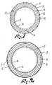
- Fig. 1 shows a first variant of the present invention with a plurality of concentric layers of strip-shaped flat explosive
- Fig. 2 shows another type of charge produced from helically-wound layers of strip-shaped flat explosives.
- reference No. 1 designates flat explosive, 2 glue joints and 3 an outer reinforcement and/or buffer; and 4 a tamping.
- a suitable thickness for the flat explosive contemplated here may be from 3 to 10 mm.
- the components were mixed in vacuum in a planetary-type mixer at 10 mm Hg.
- the composite mass was poured onto a silicon-coated substrate. Silicon of the condensation type was employed.
- the flat explosive was so elastic that it could be bent to a curvature of 20 mm without cracking.
Landscapes
- Chemical & Material Sciences (AREA)
- Engineering & Computer Science (AREA)
- Crystallography & Structural Chemistry (AREA)
- Organic Chemistry (AREA)
- Mechanical Engineering (AREA)
- Life Sciences & Earth Sciences (AREA)
- Molecular Biology (AREA)
- Dispersion Chemistry (AREA)
- Health & Medical Sciences (AREA)
- Rigid Pipes And Flexible Pipes (AREA)
- Polyurethanes Or Polyureas (AREA)
- Arc Welding In General (AREA)
- Filling Or Discharging Of Gas Storage Vessels (AREA)
- Adhesives Or Adhesive Processes (AREA)
- Laminated Bodies (AREA)
- Silicates, Zeolites, And Molecular Sieves (AREA)
Abstract
Description
- The present invention relates to a method of producing annular explosive charges for explosive jointing of large-diameter pipes such as pipelines, and to charges produced according to the method.
- Explosive jointing may be effected by explosive welding or by some type of shrink joint. As a rule, explosive jointing of large-diameter pipes such as pipelines is effected using interiorly placed annular charges which act against an exteriorly placed support or abutment. In order to provide a completely satisfactory joint, the charges must abut quite closely to the inner surface of the pipe. Minor deviations from circular configuration in the pipe may, in such operations, be compensated for in that the charge is made elastically deformable. However, the requirement of a special charge diameter for each pipe diameter remains, as well as the requirement of a good connection between the outside of the charge and the inner surface of the pipe. Moreover, the fact that the charge may not be so elastically deformable that it fails to be self-supporting may result in the situation that standard charges cannot always be used in such pipes whose dimensional tolerances lie at the extreme margins of accepted tolerance ranges for the pipe in question. Of necessity, the dimensional tolerances for such large-diameter pipes as pipelines are quite broad. Hence, a plurality of different charge dimensions for one and the same type of pipe may be necessary, and this, of course, increases costs.
- The standard method within the prior art for producing such annular charges intended for explosion welding has been to cast the charges. This is quite a circumstantial procedure if the intention is to produce a plurality of charges of different, but relatively similar, accurately specified outer diameters.
- Relevant types of such explosive charges intended for explosive welding of pipes are known through FR-A-2 537 244. The different charges according to said patent all consist of at least one annular explosive maincharge and a disc-shaped booster charge and these two parts are said to be produced as a unit. A particular type of maincharge is shown on fig 8 of said document. Said maincharge consists of three concentric layers of explosives and two intermediate layers of inert material. The latter material is exemplified as masonite a certain type of hard wood fibre board. No indication is however made in the French text how this charge was produced even though it is quite clear from the original Swedish priority text that the inventor intended to produce his charges by casting. Flexible explosives which might be useful for the preparation of annular explosive charges for explosive jointing of pipes are well known in the art. FR-A-2 225 979 e g describes such explosives comprising curable polyurethanes as binders.
- The object of the present invention is to offer a practical and versatile method of producing annular charges for explosive jointing of large-diameter pipes such as pipelines. The method according to the invention is characterized in that the charges are formed from strip-shaped, elastically deformable flat explosives which is wound and joined to form a circular ring of uniform thickness with the desired outer diameter comprising a plurality of closely abutting layers.
- If, in this operation, the strip-shaped flat explosive is wound, its ends must be bevelled. One method fo directly producing such strip-shaped flat explosive which is bevelled at its ends is to cast the explosive in a horizontal mould which is progressively shallower towards its ends. The inclination of the shallow sloping in the mould must, in this instance, be equal, at one end, to the thickness of the flat explosive divided by the outer periphery of the currently contemplated charge, and at the other end equal to the thickness of the flat explosive divided by the inner periphery of the currently contemplated charge. Besides, casting in a horizontal mould is probably the best method of producing the flat explosives of the type under consideration here. In this operation, the mould is suitably interiorly coated with silicon or teflon. In this mould, which may be provided with an interlay so as directly to provide the desired strip width (which, however, may also be realized by other suitable means, such as by cutting of a large flat explosive panel), the explosive is cast preferably mixed with a suitable binder which, at the same time, reduces the VOD (velocity of detonation) of the charge, a high-density filler to increase the density of the charge, and gas blisters in the form of gas-filled microspheres of glass or plastic to reduce the critical diameter of the charge and guarantee reliable total initiation, and possibly also a surface-active agent such as lecitine to increase the flow properties of the mixture. Another method of improving the flow properties of the mould mixture so that it flows out to a horizontal layer of uniform thickness in the mould is to employ particulate components as explosive and filler, with a carefully adapted particle size distribution.
- As has been mentioned above, the charge preferably should contain a binder. Said binder may be a polymer binder which hardens at room temperature and permits casting of charges. The binder may not have any negative effect on the explosive by an uncontrollable exothermic curing process and must, in the hardened state, impart to the charge desired flexibility such as sufficient elasticity and self-bearing properties. As a rule, a content of approx 50 per cent polymer binder should give the desired properties.
- Explosives suitable for explosive jointing are primarily pentyl, but also TNT, octogene, hexogene and ammonium nitrate could probably be employed.
- According to one preferred variation of the present invention, use is made of a polyurethane-based binder system comprising one of the di-isocyanates disclosed below or their isomeric mixtures (ratio 1:1) and a polyhydroxy compound on a ε-caprolactone basis.
- In the physical application of the method according to the present invention, use may be made, as polyisocyanates, of unitary substance or mixtures thereof. The polyisocyantes must have at least two NCO groups. Polyisocyanates with up to six NCO groups may also be employed. The polyisocyantes may have aliphatic, cyclo-aliphatic, araliphatic, aromatic or heterocyclic molecular structure.
- As examples of appropriate polyisocyanates, the following might be mentioned:
2,4-toluene di-isocyanate; and
2,6-toluene di-isocyanate
or their isomeric mixtures
diphenylene methane-4,4-di-isocyanate, diphenyl dimethyl methane-4,4-di-isocyanate, triphenyl-4,4,4-tri-isocyanate, phenylene-1,4-di-isocyanate-2,2-6,6-tetramethyl diphenyl methane-4,4-di-isocyanate, diphenyl-4,4-di-isocyanate, diphenyl ether-4,4-di-isocyanate or their halogen substituted derivates
2,6-di-isopropylene-1,3-di-isocyanate, m-xylene-di-isocyanate, p-xylene-di-isocyanate, tetramethyl-p-xylene-di-isocyanate, dimers of toluene-2,4-di-isocyanate, cyclohexane-1,4-di-isocyanate, 1,2,3,4,5,6-hexahydrodiphenyl methane-4,4-di-isocyanate, naphthalene-1,5-di-isocyanate. - Instead of the above-mentioned isocyanates, a multiplicity of additional products with isocyanate end groups may be employed. These additional products are manufactured in such a manner that a polyhydroxy compound is reacted with polyisocyanate in such a ratio that there will be obtained at least two isocyanate groups per molecule in excess. In certain cases, the excess of isocyanate groups may amount to six per molecule.
- The polyhydroxy compounds usable for the manufacture according to the present invention may be summarized under the heading of polyethers. These polyethers may, in their nature, be based on aliphatic or aromatic molecular structures. The number of hydroxy groups per molecule available for the reaction with the polyisocyanates may vary between two and six. As examples of such compounds, mention might be made of those manufactured from aliphatic diols, triols, tetrols, pentols and hexols, as well as aliphatic diamines as initiators. These aliphatic polyols and diamines are suitably straight chains containing from two to six carbon atoms. By an addition of ethylene oxide, propylene oxide or tetrahydrofurane to the initiators, there will be obtained two to six functional products with molecular weights varying between 100 and 10 000. These above-described polyethers are aliphatic compounds. However, for producing the mould compositions according to the present invention, use may advantageously also be made of polyethers on an aromatic basis with five or six-linked rings. Examples of such compounds are reaction products between ethylene oxide, propylene oxide and tetrahydrofurane, respectively, and di-hydroxy-diphenylene urethane, di-hydroxy-diphenylene propane, di-hydroxy-diphenyl or di-hydroxy-hydantoin.
- These aromatic polyethers may be embraced in the following general formulae:

wherein A designates a single grouping,
p is either 1 or 3
and R = H or CH₃ where p = 1
and R = H where p = 3
and n = 1-5 - The molecular weight of these compounds lies between 300 and 800. These above-described compounds react with polyisocyanates by polyaddition.
- The following systems are usable thanks to their low viscosity, low exotherm and long pot life.
- Isophorone-di-isocyanate (3-isocyanatomethyl-3,5,5-trimethyl cyclohexyl-isocyanate).

- The NCO content for these isocyanates should lie between 30 and 40%.
- As polyhydroxy compounds, use is preferably made of polyethers on an ε-caprolactone basis.

wherein R- may be any OH-terminated compound whatever. However, the condition is that the OH group must be primary.
- Polyesters suffer from the drawback that they are often highly-viscous, brittle and give a rapid and high increase in temperature on polymerization.
- Low-viscous polyester systems contain hazardous monomers. The catalyst types used for polymerization of polyesters are inhibited by nitro compounds and nitrate esters. Consequently, polyesters are unsuitable for this purpose.
- On the other hand, silicons which have elastic properties may be used, at least in certain cases. Moreover, these harden completely at room temperature without rapid exotherms. On the other hand, their price level is clearly disadvantageous as compared with isophorone-based polyurethane systems. Moreover, viscosity is often higher for silicon systems. Nor is silicon as strong as polyurethane systems. On the other hand, epoxy resins cannot, as a rule, be employed, since the catalysts are often incompatible with explosive.
- In order to attain a sufficient degree of cohesion, the different layers of the charge should be glued to one another. This may either be effected using a separate glue or by utilizing the polymer binder. In the first case, the glue surfaces may, for example, be coated with a curing polyurethane which contains an excess of polyol. In the second case, the hardening of the polymer binder may be delayed in its surface layer facing the mould. This may be effected, for example, by coating the inside of the mould with a certain type of silicon rubber which has an inhibiting effect on polyurethane hardening.
- The glueing of the different layers to one another may also be utilized to divide up the charge by means of inert layers which reduce the VOD of the charge. The charge may also be reinforced by glass fibre matting or other material in conjunction with the moulding of the charge.
- The nature of the present invention and its aspects have been defined in the appended claims. Referring to the drawings, Fig. 1 shows a first variant of the present invention with a plurality of concentric layers of strip-shaped flat explosive, while Fig. 2 shows another type of charge produced from helically-wound layers of strip-shaped flat explosives. On the figures, reference No. 1 designates flat explosive, 2 glue joints and 3 an outer reinforcement and/or buffer; and 4 a tamping. A suitable thickness for the flat explosive contemplated here may be from 3 to 10 mm.
- The following components and amounts were mixed:
Isophoron di-isocyanate: 15%
Polyol: 30%
Pot life > 1 hour
Coarse-grained pentyl: 24%
Fine-grained pentyl: 6%
Glass microspheres: 3%
Zinc powder: 21.5%
Lecitine: 0.5% - The components were mixed in vacuum in a planetary-type mixer at 10 mm Hg.
- Thereafter, the composite mass was poured onto a silicon-coated substrate. Silicon of the condensation type was employed.
- After 12 hours, the panel was removed from the mould. Its underside was tacky as has been mentioned above. Pieces were cut out from the panel and were then glued together to form an annular charge according to Fig. 2. This charge was subsequently employed as a patented explosive welding charge.
- The flat explosive was so elastic that it could be bent to a curvature of 20 mm without cracking.
Claims (8)
- A method of producing annular charges for explosive jointing of large-diameter pipes, such as pipelines characterized in that the charges are formed from strip-shaped, elastically deformable flat explosive which is wound and joined to form a circular ring of uniform thickness with the desired outer diameter, comprising a plurality of closely abutting layers.
- A method as claimed in claim 1, characterized in that the strip-shaped flat explosive is wound in a plurality of continuous superposed layers.
- The method as claimed in claim 1, characterized in that the strip-shaped flat explosive is wound in a plurality of annular, concentrically disposed layers.
- The method as claimed in any one of the preceding claims, characterized in that the different layers of strip-shaped flat explosive are wound on a matrix.
- The method as claimed in claim 2, characterized in that the flat explosive is bevelled at its ends prior to the winding operation.
- The method as claimed in any one of the preceding claims, characterized in that the different layers are glued to one another; and that the finished charge is possibly reinforced by glass fibre fabric or the like glued thereon.
- The method as claimed in any one of claims 1-5, characterized in that inert layers are applied in the joints between the different layers of strip-shaped flat explosive.
- A charge produced by the method according to any one of claims 1-7, characterized in that it consists of a strip-shaped flat explosive wound to form a circular ring of uniform thickness and containing a high-energy explosive such as TNT, pentyl, octogene or hexogene, or alternatively ammonium nitrate, a high density filler to increase the density of the charge consisting of a metal or metal oxide powder, microspheres and a polymer binder based on one of the following di-isocyanates:
- Isophoron di-isocyanate (= 3-isocyanateomethyl-3,5,5-trimethyl cyclohexyl isocyanate),- 2,2,4-trimethyl hexamethylene di-isocyanate- 2,4,4-trimethyl hexamethylene di-isocyanate- or their isomeric mixtures (ratio 1:1) and with an NCO content of between 30 and 40%
and an ε-caprolactone-based polyether.
Priority Applications (1)
| Application Number | Priority Date | Filing Date | Title |
|---|---|---|---|
| AT86850211T ATE69442T1 (en) | 1985-06-20 | 1986-06-13 | EXPLOSIVE CHARGES. |
Applications Claiming Priority (2)
| Application Number | Priority Date | Filing Date | Title |
|---|---|---|---|
| SE8503080A SE452799B (en) | 1985-06-20 | 1985-06-20 | SET TO MAKE ANIMAL CHARGES AND ACCORDING TO SETS OF CHARGES |
| SE8503080 | 1985-06-20 |
Publications (2)
| Publication Number | Publication Date |
|---|---|
| EP0208666A1 EP0208666A1 (en) | 1987-01-14 |
| EP0208666B1 true EP0208666B1 (en) | 1991-11-13 |
Family
ID=20360657
Family Applications (1)
| Application Number | Title | Priority Date | Filing Date |
|---|---|---|---|
| EP86850211A Expired - Lifetime EP0208666B1 (en) | 1985-06-20 | 1986-06-13 | Improvements to explosive charges |
Country Status (7)
| Country | Link |
|---|---|
| US (1) | US4706567A (en) |
| EP (1) | EP0208666B1 (en) |
| AT (1) | ATE69442T1 (en) |
| CA (1) | CA1273845A (en) |
| DE (1) | DE3682451D1 (en) |
| NO (1) | NO165665C (en) |
| SE (1) | SE452799B (en) |
Families Citing this family (9)
| Publication number | Priority date | Publication date | Assignee | Title |
|---|---|---|---|---|
| US5238512A (en) * | 1987-06-04 | 1993-08-24 | Exploweld Ab | Water resistant elastic explosive mixture |
| US4799980A (en) * | 1988-01-28 | 1989-01-24 | Reed Jr Russell | Multifunctional polyalkylene oxide binders |
| US5240523A (en) * | 1988-07-11 | 1993-08-31 | Thiokol Corporation | Binders for high-energy composition utilizing cis-,cis-1,3,5-tri(isocyanatomethyl)cyclohexane |
| FR2667808A1 (en) * | 1990-01-12 | 1992-04-17 | Nitro Bickford Gie | Method and device for the internal lining of pipes and for connecting pipes by means of such linings |
| DE4030389C1 (en) * | 1990-09-26 | 1992-01-16 | Heinrich Dr. Moresnet Be Hampel | Composite material tube - mfd. by winding metal foil on steel core and joining outermost or innermost layers explosively |
| US5600089A (en) * | 1994-12-07 | 1997-02-04 | The United States Of America As Represented By The Secretary Of The Navy | Highly plasticized elastomers |
| CA2166748A1 (en) * | 1995-01-14 | 1996-07-15 | Sek Kwan Chan | Pyrotechnic ignition device |
| NO20005773A (en) * | 2000-11-14 | 2002-04-15 | Nammo Raufoss As | Pyrotechnic charge structure |
| US6554927B1 (en) * | 2000-11-24 | 2003-04-29 | Sigmabond Technologies Corporation | Method of explosive bonding, composition therefor and product thereof |
Family Cites Families (10)
| Publication number | Priority date | Publication date | Assignee | Title |
|---|---|---|---|---|
| US3793099A (en) * | 1960-05-31 | 1974-02-19 | Aerojet General Co | Solid propellant with polyurethane binder |
| DE2119336C3 (en) * | 1971-04-21 | 1980-02-14 | Werner Dr. 6231 Schwalbach Diepold | Process for the production of castable composite double-base solid propellants |
| US4263070A (en) * | 1973-01-17 | 1981-04-21 | Thiokol Corporation | Thermally stable gun and caseless cartridge propellants |
| US4072702A (en) * | 1976-12-06 | 1978-02-07 | The United States Of America As Represented By The Secretary Of The Army | Tri-functional isocyanate crosslinking agents for hydroxy-terminated polybutadiene binders |
| US4284442A (en) * | 1978-03-13 | 1981-08-18 | The United States Of America As Represented By The Secretary Of The Army | Castable TNT compositions containing a broad spectrum preformed thermoplastic polyurethane elastomer additive |
| US4216039A (en) * | 1978-11-20 | 1980-08-05 | The United States Of America As Represented By The Secretary Of The Army | Smokeless propellant compositions having polyester or polybutadiene binder system crosslinked with nitrocellulose |
| US4280407A (en) * | 1979-05-21 | 1981-07-28 | C-I-L Inc. | Explosive package assembly |
| US4354433A (en) * | 1980-03-18 | 1982-10-19 | Pengo Industries, Inc. | Apparatus for cutting pipe |
| SE458302B (en) * | 1982-12-03 | 1989-03-13 | Nitro Nobel Ab | DEVICE FOR ASTADDOM A CUTTING CONNECTION BETWEEN TWO METALLIC PIPES BY EXPLOSION WELDING IN A SURROUNDING DESIRED MEDIUM LIKE THE WATER |
| DE3332224A1 (en) * | 1983-09-07 | 1985-03-21 | Rheinmetall GmbH, 4000 Düsseldorf | RE-COMPRESSED DRIVE CHARGE, METHOD FOR THEIR PRODUCTION AND DEVICE FOR CARRYING OUT THE METHOD |
-
1985
- 1985-06-20 SE SE8503080A patent/SE452799B/en not_active Application Discontinuation
-
1986
- 1986-06-13 EP EP86850211A patent/EP0208666B1/en not_active Expired - Lifetime
- 1986-06-13 AT AT86850211T patent/ATE69442T1/en not_active IP Right Cessation
- 1986-06-13 DE DE8686850211T patent/DE3682451D1/en not_active Expired - Fee Related
- 1986-06-19 CA CA000511923A patent/CA1273845A/en not_active Expired - Fee Related
- 1986-06-19 NO NO862456A patent/NO165665C/en unknown
- 1986-06-20 US US06/876,446 patent/US4706567A/en not_active Expired - Fee Related
Also Published As
| Publication number | Publication date |
|---|---|
| CA1273845A (en) | 1990-09-11 |
| SE452799B (en) | 1987-12-14 |
| NO862456D0 (en) | 1986-06-19 |
| NO165665B (en) | 1990-12-10 |
| US4706567A (en) | 1987-11-17 |
| SE8503080L (en) | 1986-12-21 |
| SE8503080D0 (en) | 1985-06-20 |
| ATE69442T1 (en) | 1991-11-15 |
| NO165665C (en) | 1991-03-20 |
| EP0208666A1 (en) | 1987-01-14 |
| DE3682451D1 (en) | 1991-12-19 |
| NO862456L (en) | 1986-12-22 |
Similar Documents
| Publication | Publication Date | Title |
|---|---|---|
| CA1275529C (en) | High performance two-component epoxy structural adhesives with chemical thixotropy | |
| US4706567A (en) | Explosive charges | |
| EP0256162B1 (en) | Polyol/polyepoxide/polyisocyanate adhesive composition and its use | |
| US4803019A (en) | Process for forming a liner and cast propellant charge in a rocket motor casing | |
| KR101110948B1 (en) | Adhesive, composite material containing the adhesive, and process for producing the composite material | |
| US4187215A (en) | Polymeric isocyanate-hydroxy terminated polybutadiene compositions | |
| EP0254255B1 (en) | Sag resistant two-component urethane adhesives with improved thermal stability | |
| US4740539A (en) | Flexible two-component epoxy structural adhesives | |
| JP2689941B2 (en) | Flexible polyepoxide resin containing poly-N-methylated secondary amine | |
| US4477527A (en) | Shapes for sealing or joining materials together | |
| US4718346A (en) | Explosive charge for the explosive welding of large diameter pipes, and a method for its manufacture | |
| US4000023A (en) | Bonding agents for polyurethane | |
| CN109563232A (en) | With the mechanical performance not being affected by temperature substantially and high-intensitive two component polyurethane adhesive | |
| US4328281A (en) | Dimer isocyanate liner compositions | |
| AU674162B2 (en) | Process for using a synthetic resin system | |
| US4728737A (en) | High performance two-component epoxy structural adhesive with chemical thixotropy | |
| CA1056984A (en) | Curable binding systems | |
| US6051087A (en) | Low smoke rocket motor liner compositions | |
| US4726868A (en) | Polyol/polyepoxide/polyurethane adhesive | |
| US4053680A (en) | Process for bonding polymers | |
| JPH0240272B2 (en) | SETSUCHAKUHOHOOYOBISORENIMOCHIIRUSETSUCHAKUZAISOSEIBUTSU | |
| JPH0135023B2 (en) | ||
| US3145192A (en) | Acetylenic polyurethanes useful as propellants | |
| JPH05163478A (en) | Thermosetting adhesive composition and bonding method using the same | |
| JPH0759916B2 (en) | Rocket motor manufacturing method |
Legal Events
| Date | Code | Title | Description |
|---|---|---|---|
| PUAI | Public reference made under article 153(3) epc to a published international application that has entered the european phase |
Free format text: ORIGINAL CODE: 0009012 |
|
| AK | Designated contracting states |
Kind code of ref document: A1 Designated state(s): AT BE CH DE FR GB IT LI NL SE |
|
| 17P | Request for examination filed |
Effective date: 19870630 |
|
| 17Q | First examination report despatched |
Effective date: 19890420 |
|
| GRAA | (expected) grant |
Free format text: ORIGINAL CODE: 0009210 |
|
| AK | Designated contracting states |
Kind code of ref document: B1 Designated state(s): AT BE CH DE FR GB IT LI NL SE |
|
| REF | Corresponds to: |
Ref document number: 69442 Country of ref document: AT Date of ref document: 19911115 Kind code of ref document: T |
|
| ET | Fr: translation filed | ||
| REF | Corresponds to: |
Ref document number: 3682451 Country of ref document: DE Date of ref document: 19911219 |
|
| ITF | It: translation for a ep patent filed | ||
| PGFP | Annual fee paid to national office [announced via postgrant information from national office to epo] |
Ref country code: GB Payment date: 19920602 Year of fee payment: 7 |
|
| PGFP | Annual fee paid to national office [announced via postgrant information from national office to epo] |
Ref country code: FR Payment date: 19920605 Year of fee payment: 7 Ref country code: CH Payment date: 19920605 Year of fee payment: 7 |
|
| PGFP | Annual fee paid to national office [announced via postgrant information from national office to epo] |
Ref country code: BE Payment date: 19920617 Year of fee payment: 7 |
|
| PGFP | Annual fee paid to national office [announced via postgrant information from national office to epo] |
Ref country code: AT Payment date: 19920623 Year of fee payment: 7 |
|
| PGFP | Annual fee paid to national office [announced via postgrant information from national office to epo] |
Ref country code: NL Payment date: 19920630 Year of fee payment: 7 |
|
| PGFP | Annual fee paid to national office [announced via postgrant information from national office to epo] |
Ref country code: DE Payment date: 19920825 Year of fee payment: 7 |
|
| PLBE | No opposition filed within time limit |
Free format text: ORIGINAL CODE: 0009261 |
|
| STAA | Information on the status of an ep patent application or granted ep patent |
Free format text: STATUS: NO OPPOSITION FILED WITHIN TIME LIMIT |
|
| 26N | No opposition filed | ||
| PG25 | Lapsed in a contracting state [announced via postgrant information from national office to epo] |
Ref country code: GB Effective date: 19930613 Ref country code: AT Effective date: 19930613 |
|
| PG25 | Lapsed in a contracting state [announced via postgrant information from national office to epo] |
Ref country code: LI Effective date: 19930630 Ref country code: CH Effective date: 19930630 Ref country code: BE Effective date: 19930630 |
|
| PGFP | Annual fee paid to national office [announced via postgrant information from national office to epo] |
Ref country code: SE Payment date: 19930810 Year of fee payment: 8 |
|
| BERE | Be: lapsed |
Owner name: NOBEL KEMI A.B. Effective date: 19930630 |
|
| PG25 | Lapsed in a contracting state [announced via postgrant information from national office to epo] |
Ref country code: NL Effective date: 19940101 |
|
| GBPC | Gb: european patent ceased through non-payment of renewal fee |
Effective date: 19930613 |
|
| NLV4 | Nl: lapsed or anulled due to non-payment of the annual fee | ||
| PG25 | Lapsed in a contracting state [announced via postgrant information from national office to epo] |
Ref country code: FR Effective date: 19940228 |
|
| REG | Reference to a national code |
Ref country code: CH Ref legal event code: PL |
|
| PG25 | Lapsed in a contracting state [announced via postgrant information from national office to epo] |
Ref country code: DE Effective date: 19940301 |
|
| REG | Reference to a national code |
Ref country code: FR Ref legal event code: ST |
|
| PG25 | Lapsed in a contracting state [announced via postgrant information from national office to epo] |
Ref country code: SE Effective date: 19940614 |
|
| EUG | Se: european patent has lapsed |
Ref document number: 86850211.3 Effective date: 19950110 |
|
| EUG | Se: european patent has lapsed |
Ref document number: 86850211.3 |
|
| PG25 | Lapsed in a contracting state [announced via postgrant information from national office to epo] |
Ref country code: IT Free format text: LAPSE BECAUSE OF NON-PAYMENT OF DUE FEES;WARNING: LAPSES OF ITALIAN PATENTS WITH EFFECTIVE DATE BEFORE 2007 MAY HAVE OCCURRED AT ANY TIME BEFORE 2007. THE CORRECT EFFECTIVE DATE MAY BE DIFFERENT FROM THE ONE RECORDED. Effective date: 20050613 |