EP0206660B1 - Articulated boom mechanism for unloading bulk solid material from a ship - Google Patents
Articulated boom mechanism for unloading bulk solid material from a ship Download PDFInfo
- Publication number
- EP0206660B1 EP0206660B1 EP86304511A EP86304511A EP0206660B1 EP 0206660 B1 EP0206660 B1 EP 0206660B1 EP 86304511 A EP86304511 A EP 86304511A EP 86304511 A EP86304511 A EP 86304511A EP 0206660 B1 EP0206660 B1 EP 0206660B1
- Authority
- EP
- European Patent Office
- Prior art keywords
- boom
- articulation member
- construction
- actuator means
- support base
- Prior art date
- Legal status (The legal status is an assumption and is not a legal conclusion. Google has not performed a legal analysis and makes no representation as to the accuracy of the status listed.)
- Expired - Lifetime
Links
- 230000007246 mechanism Effects 0.000 title claims description 46
- 239000011343 solid material Substances 0.000 title claims description 25
- 238000010276 construction Methods 0.000 claims description 47
- 239000000463 material Substances 0.000 claims description 7
- 230000001419 dependent effect Effects 0.000 claims 1
- 239000012530 fluid Substances 0.000 description 4
- 229910000831 Steel Inorganic materials 0.000 description 3
- 230000000295 complement effect Effects 0.000 description 3
- 239000010959 steel Substances 0.000 description 3
- 230000008602 contraction Effects 0.000 description 2
- 238000006073 displacement reaction Methods 0.000 description 2
- 230000000694 effects Effects 0.000 description 2
- 238000003032 molecular docking Methods 0.000 description 2
- 230000003014 reinforcing effect Effects 0.000 description 2
- 230000000087 stabilizing effect Effects 0.000 description 1
- 230000032258 transport Effects 0.000 description 1
Images



Classifications
-
- B—PERFORMING OPERATIONS; TRANSPORTING
- B65—CONVEYING; PACKING; STORING; HANDLING THIN OR FILAMENTARY MATERIAL
- B65G—TRANSPORT OR STORAGE DEVICES, e.g. CONVEYORS FOR LOADING OR TIPPING, SHOP CONVEYOR SYSTEMS OR PNEUMATIC TUBE CONVEYORS
- B65G47/00—Article or material-handling devices associated with conveyors; Methods employing such devices
- B65G47/34—Devices for discharging articles or materials from conveyor
- B65G47/44—Arrangements or applications of hoppers or chutes
-
- B—PERFORMING OPERATIONS; TRANSPORTING
- B63—SHIPS OR OTHER WATERBORNE VESSELS; RELATED EQUIPMENT
- B63B—SHIPS OR OTHER WATERBORNE VESSELS; EQUIPMENT FOR SHIPPING
- B63B27/00—Arrangement of ship-based loading or unloading equipment for cargo or passengers
- B63B27/22—Arrangement of ship-based loading or unloading equipment for cargo or passengers of conveyers, e.g. of endless-belt or screw-type
Definitions
- This invention relates to a boom for unloading bulk solid material from, for example, a ship, and more particularly, to a boom with an articulated construction.
- Ships at present generally utilize a single boom of unitary construction for unloading bulk solid material.
- a boom has its one end pivoted to the deck of the ship with its outer end being free to move through a generally semi-circular path.
- the elevation of the outer end of the boom may also be adjusted such that an angle of up to fifteen degrees is formed between the boom and the deck of the ship.
- a conveyor system extends through the boom such that bulk solid material emptied from the hold or holds of the ship onto the one end of the boom is transported along the boom and emptied from the other end of the boom.
- the difficulty that has been encountered with the use of a single span boom for unloading bulk solid material from a ship relates to the time and effort required in positioning the ship such that the outer end of the boom achieves a desired position.
- the outer end of the boom When extending over the side of the ship, the outer end of the boom describes an arc which varies in its displacement from the ship with its distance along the ship. In some cases the outer end of the boom extends to such a great distance beyond the side of the ship during the unloading operation that a second ship must be interposed between the ship and the material receiving site to stabilize the position of the ship.
- an articulated boom mechanism for use in conveying bulk solid material, such as bulk solid material capable of being carried by a ship, the boom mechanism comprising: a first boom construction one end of the first boom construction being adapted to be pivotally mounted to a support base, such as a portion of a ship's structure, by a universal-type connection, the first boom construction having a first conveyor means extending through it for transporting material from one of its ends to the other of its ends; first actuator means adapted to extend between the support base and the first boom construction for selectively varying the relative vertical angle between the first boom construction and the support base; first powered pivot means for rotating the first boom construction relative to the support base through desired horizontal angles; characterized by an-articulation member, comprising first and second portions which are relatively rotatable about an axis of relative rotation, the first portion being pivotally mounted to the other end of the first boom construction; a second boom construction, one end of the second boom construction being pivotally mounted to the second portion of the articulation member, the second boom construction having
- the articulation member may be a tube adapted in use to have its symmetry axis extending generally vertically, the tube in use having an upper portion defining the one portion of the articulation member and a lower portion defining the other portion of the articulation member.
- the upper and lower portions of the tube are connected by an annular bearing extending therebetween.
- the other end of the first conveyor means is adapted to extend into the upper portion of the tube and the one end of the second conveyor means is adapted to extend into the lower portion of the tube. In such arrangement, bulk solid material falls from the other end of the one conveyor means through the tube onto the one end of the second conveyor means.
- a first part of the annular bearing may be formed on the lower edge of the upper portion of the tube with a second part of the annular bearing formed on the upper edge of the lower portion of the tube.
- the one of the first and second parts of the annular bearing has first gear teeth extending along its periphery
- the other of the first and second parts of the annular bearing has a series of motors mounted on its periphery with each motor driving a set of gear teeth adapted to engage the first gear teeth.
- the articulated boom mechanism may also comprise a chute adapted to be mounted within the articulation member.
- the chute is adapted to be mounted to the upper portion of the tube and to extend generally centrally through the tube.
- the upper end of the chute is positioned in use under an outer end of the first conveyor means, that outer end being positioned proximate of the other end of the first boom construction.
- the lower end of the chute is positioned in use above an inner end of the second conveyor means, that inner end being positioned proximate of the one end of the second boom construction.
- the chute guides bulk solid material leaving the first conveyor means onto the second conveyor means.
- the first boom construction may comprise a first boom member and a shaft means, the shaft means being adapted to be mounted on the support base e.g. the structure of a ship, to rotate normal to support base i.e. the deck of the ship.
- the first boom member is adapted to be pivotally mounted on the shaft means by an axle extending parallel to the deck of the ship.
- the first boom member may be a tube of circular cross-section.
- the second boom construction may comprise a second boom member, that second boom member being a tube of rectangular cross-section.
- the first pivot means may comprise hydraulic actuator means, rack means and pinion means.
- a stationary portion of the hydraulic actuator means is adapted to be mounted to the structure of the ship, the pinion means is adapted to extend along the periphery of the shaft means, and the rack means is adapted to connect to a movable portion of the hydraulic actuator means and to engage the pinion means.
- the first boom member may be of sufficiently greater length than the second boom construction that is in use. In one orientation of the articulated boom mechanism, the second boom construction is capable of extending completely under the first boom member.
- the first actuator means may be adapted to extend between the structure of the ship and the first boom construction and the second actuator means may be adapted to extend between the first boom construction and the articulation member.
- actuation of the first actuator means results in a corresponding actuation of the further actuator means for maintaining the articulation member at the fixed orientation relative to the structure of the ship.
- the first end of the first conveyor means may be defined by a roller having a rotational axis adapted to extend generally concentrically with the axis of the pivotal mounting around which the articulation member pivots relative to the first boom construction.
- the lower end of the chute is adapted to be positioned proximate of the axis of the pivotal mounting around which the second boom construction pivots relative to the articulation member.
- the articulated boom mechanism of the present invention provides improvements over a single span boom on the bulk solid material unloading operation in at least two significant ways. Firstly, a ship utilizing the articulated boom mechanism can assume a greater variety of docking positions without consideration having to be given to the effect of such docking positions on the material unloading position of the boom. Secondly, once the ship has been docked the outer end of the articulated boom mechanism may be oriented to assume any selected displacement from the ship at any selected distance along the ship. The time taken to initiate reclaiming of the bulk solid material from the ship is significantly reduced, and the sometime requirement for interposing of a second ship for stabilizing the unloading operation is eliminated. A further benefit of the articulated boom mechanism is that it allows bulk solid material to be transferred from one ship to a second ship when the two ships are positioned so as to have abutting sides; with the single span unloading boom such transfers were not generally possible.
- ship 10 has a series of holds extending serially along its length, each hold being capable of holding a portion of a bulk solid material cargo.
- a series of belts terminating in belt 11, illustrated in outline in Figure 1 transports bulk solid material from the holds to overhang structure 12, that structure extending forward of the raised superstructure 13 at the rear of ship 10.
- the bulk solid material is emptied from belt 11 as that belt moves within overhang structure 12 and falls through a flexible cylindrical hood 14 into the base of the articulated boom mechanism, that mechanism being generally designated 15.
- Articulated boom mechanism 15 is supported on ship 10 by a base structure 20 mounted on the deck of ship 10 and by an overhang member 21 extending forward of raised superstructure 13 and above overhang structure 12.
- base structure 20 has a sloped lower portion and a generally rectangular upper portion, with a pair of hydraulic piston chambers 22 extending from each of an opposite pair of sides of the rectangular upper portion.
- Each facing pair of hydraulic piston chambers 22 contains a piston (not shown) connected to an opposite end of a common rack member 23, hydraulic fluid entering one of the facing pair of chambers 22 moving the rack member 23 in one direction while hydraulic fluid is being expelled to a reservoir from the other one of the chambers.
- the hydraulic fluid is forced simultaneously into a diagonally-opposite pair of the chambers 22 such that the pair of rack -members 23 move simultaneously an equal distance but in opposed directions.
- a pinion member 24 Centered between the pair of rack members 23 is a pinion member 24 having teeth on its periphery which engage the teeth of the pair of rack members 23.
- Pinion member 24 is mounted on bearings for free rotation and has a spline groove 25 machined into its inner periphery.
- a turret member 27 with an integral splined shaft is mounted on pinion member 24 such that its spline sits in spline groove 25.
- a pair of trunnions 28 are integral with turret member 27 and extend from an opposite pair of sides of turret member 27.
- the chambers 22, rack 23, pinion member 24 and trunnion 28 form first powered pivot means.
- first boom member 30 Mounted to rotate in the pair of trunnions 28 is a first boom member 30, its one end being pivotally mounted to the pair of trunnions 28 and its other end being connected by first actuator means in the form of hydraulic actuator mechanism 31 to overhang member 21.
- the supporting connection between hydraulic actuator mechanism 31 and overhang member 21 is by means of a universal joint 32 such that rotation is possible around an axis normal to the deck of the ship and one parallel to the deck.
- Axle assembly 32 allows hydraulic actuator mechanism 31 to rotate with first boom member 30.
- hydraulic actuator mechanism 31 is pivotally connected to the outer end of first boom member 30 by a flange 33 extending from that outer end.
- First boom member 30 is a circular tube having a diameter of 10.5 feet (3.20 metres).
- the tube is formed of steel and has 0.375 inch (0.95 cm) thick walls.
- Circular reinforcing hoops of rectangular cross-section (not shown) are secured to the outside of the circular tube approximately every 10 feet (3.04 metres) along the length of the tube; the reinforcing hoops resist torsional stress placed onto first boom member 30.
- Thick steel bands 34 and 35 are placed over the respective inner and outer ends of the circular tube of first boom member 30 to distribute over the tube the load exerted by the pair of trunnions 28 and hydraulic actuator mechanism 31.
- first boom member 30 is approximately 130 feet (39.62 metres) in length.
- An articulation member 40 as best shown in Figures 4 and 5, has an upper portion 41 and a lower portion 42 pivotally connected to upper portion 41. Articulation member 40 is itself pivotally connected to the outer end of first boom member 30 by a pair of trunnions 43. A flange 44 secured to the top of articulation member 40 is connected by further actuator means in the form of hydraulic actuator mechanism 45, to the flange 33 on first boom member 30.
- Hydraulic actuator mechanisms 31 and 45 have a complementary hydraulic connection such that an extension or contraction of hydraulic actuator mechanism 31 results in a corresponding contraction or expansion of hydraulic actuator mechanism 45, the effect being that articulation member 40 maintains a constant orientation relative to the deck of the ship for all angular positions of first boom member 30; the orientation is one in which the axis of rotation between the upper portion 41 and the lower portion 42 of articulation member 40 extends normal to the deck of the ship.
- Articulation member 40 in plan view is circular in cross-section, the lower portion 42 being rotatable relative to the upper portion 41 by means of an annular bearing generally designated 50.
- Annular bearing 50 is of the type found on large cranes and is capable of carrying very heavy loading forces while still allowing the two portions of articulation member 40 to rotate relative to each other.
- Figure 6 illustrates annular bearing 50 in an enlarged sectioned side view
- Figure 7 illustrates a perspective sectioned view of the bearing.
- An upper annular frame 51 of rectangular cross-section and a corresponding lower annular frame 52 are secured to respective upper and lower complementary bearing members 53 and 54, as shown in Figure 6.
- a series of rollers 55 each of which has its axis of rotation oriented normal to the axis of rotation of its immediately-adjacent neighbours extends in a diamond-shaped race 56 defined by the facing surfaces of bearing members 53 and 54.
- a series of motors 57 are mounted to the periphery of upper annular frame 51.
- Each motor has a gear wheel 58 secured to its rotor, the series of gear wheels 58 having teeth that engage with complementary teeth on a ring gear 59 that extends around the periphery of lower annular frame 52.
- This arrangement (50, 57, 58, 59) forms second powered pivot means.
- the motors 57 are electrically connected such that all are actuated simultaneously; such actuation results in the lower portion 42 of articulation member 40 and a connected second boom member 60 rotating relative to the upper portion 41 of articulation member 40.
- the second boom member 60 has its inner end pivotally mounted by a pair of trunnions 61 to the lower portion 42 of articulation member 40, as shown in Figure 1.
- Second boom member 60 is of rectangular cross-section and is formed from steel plate 0.375 inch (0.95 cm) thick. Member 60 of the preferred embodiment is approximately 90 feet (27.43 metres) long, and is 10.5 feet (3.20 metres) wide and 6.5 feet (1.98 metres) high.
- second boom member 60 has hoops of rectangular cross-section (not shown) secured around its periphery at intervals of approximately 10 feet (3.04 metres) to assist in resisting torsional stresses.
- Second actuator means in the form of a hydraulic actuator mechanism 62, are connected between a flange 63 extending from articulation member 40 and a flange 64 secured to second boom member 60. Similar to the arrangement with hydraulic actuator mechanism 31, hydraulic actuator mechanism 62 has its one end mounted through a universal joint to flange 63 so asto allow it to rotate with the lower portion 42 of articulation member 40 and with second boom member 60.
- a first conveyor belt 67 is mounted to extend centrally through first boom member 30, and a second conveyor belts 68 is mounted to extend centerally through second boom member 60, as illustrated in Figure 5.
- One of the two end rollers 82 around which belt 67 extends is mounted so as to have its axis of rotation extending generally concentrically with the pivot axis around which articulation member 60 rotates relative to first boom member 30.
- This arrangement allows bulk solid material 70 being carried on belt 67 to consistently fall onto the inner surface of a chute 72 secured to the upper portion 41 of articulation member 40.
- the material 70 is guided by chute 72 and empties onto belt 68 of second boom member 60, guide surfaces 73 secured to member 60 preventing material from falling from the sides of belt 68.
- the lower lip of chute 72 sits above belt 68 approximately above the axis through which second boom member 60 is pivoted to the lower portion 42 of articulation member 40. That arrangement allows the lower lip of chute 72 to maintain its small spacing from belt 68 over all relative angular orientations between second boom member 60 and articulation member 40.
- Figure 8 illustrates a diametrical cross-sectional view of first boom member 30.
- Belt 67 can be seen to be supported by three rollers, a horizontal central roller 77 and an adjacent pair of inclined side rollers 78. Near either end of first boom member 30, the side rollers 78 assume a horizontal orientation with central roller 77, as illustrated in Figure 5; a similar situation is true with respect to boom member 60.
- a walkway for personnel is formed by a vertical structural element 80 and a connecting horizontal floor surface 81.
Landscapes
- Engineering & Computer Science (AREA)
- Mechanical Engineering (AREA)
- Chemical & Material Sciences (AREA)
- Combustion & Propulsion (AREA)
- Ocean & Marine Engineering (AREA)
- Ship Loading And Unloading (AREA)
Description
- This invention relates to a boom for unloading bulk solid material from, for example, a ship, and more particularly, to a boom with an articulated construction.
- Ships at present generally utilize a single boom of unitary construction for unloading bulk solid material. Such a boom has its one end pivoted to the deck of the ship with its outer end being free to move through a generally semi-circular path. The elevation of the outer end of the boom may also be adjusted such that an angle of up to fifteen degrees is formed between the boom and the deck of the ship. A conveyor system extends through the boom such that bulk solid material emptied from the hold or holds of the ship onto the one end of the boom is transported along the boom and emptied from the other end of the boom.
- Such a construction is shown for example in DD-A-72699.
- The difficulty that has been encountered with the use of a single span boom for unloading bulk solid material from a ship relates to the time and effort required in positioning the ship such that the outer end of the boom achieves a desired position. When extending over the side of the ship, the outer end of the boom describes an arc which varies in its displacement from the ship with its distance along the ship. In some cases the outer end of the boom extends to such a great distance beyond the side of the ship during the unloading operation that a second ship must be interposed between the ship and the material receiving site to stabilize the position of the ship.
- It is an object of the present invention to provide an articulated boom mechanism which provides the capability of significantly improved performance compared with the known single boom arrangement described above.
- According to the present invention there is provided an articulated boom mechanism for use in conveying bulk solid material, such as bulk solid material capable of being carried by a ship, the boom mechanism comprising: a first boom construction one end of the first boom construction being adapted to be pivotally mounted to a support base, such as a portion of a ship's structure, by a universal-type connection, the first boom construction having a first conveyor means extending through it for transporting material from one of its ends to the other of its ends; first actuator means adapted to extend between the support base and the first boom construction for selectively varying the relative vertical angle between the first boom construction and the support base; first powered pivot means for rotating the first boom construction relative to the support base through desired horizontal angles; characterized by an-articulation member, comprising first and second portions which are relatively rotatable about an axis of relative rotation, the first portion being pivotally mounted to the other end of the first boom construction; a second boom construction, one end of the second boom construction being pivotally mounted to the second portion of the articulation member, the second boom construction having a second conveyor means extending through it for transporting bulk solid material from one of its ends to the other of its ends; second actuator means extending between the articulation member and the second boom, construction for selectively varying the relative vertical angle between the articulation member and the second boom construction; further actuator means for maintaining the axis of relative rotation defined by the articulation member at a substantially fixed upright orientation relative to the support base for all angular positions assumed by the first boom construction relative to the support base; second powered pivot means for rotating the second portion of the articulation member and the second boom construction mounted thereto relative to the first portion of the articulation member about said axis of relative rotation through desired horizontal angles; whereby bulk solid material placed onto one of the conveyor means is subsequently discharged from the other conveyor means after moving through a path determined by the first and second actuator means and the first and second pivot means.
- The articulation member may be a tube adapted in use to have its symmetry axis extending generally vertically, the tube in use having an upper portion defining the one portion of the articulation member and a lower portion defining the other portion of the articulation member. The upper and lower portions of the tube are connected by an annular bearing extending therebetween. The other end of the first conveyor means is adapted to extend into the upper portion of the tube and the one end of the second conveyor means is adapted to extend into the lower portion of the tube. In such arrangement, bulk solid material falls from the other end of the one conveyor means through the tube onto the one end of the second conveyor means. A first part of the annular bearing may be formed on the lower edge of the upper portion of the tube with a second part of the annular bearing formed on the upper edge of the lower portion of the tube. In such arrangement, the one of the first and second parts of the annular bearing has first gear teeth extending along its periphery, and the other of the first and second parts of the annular bearing has a series of motors mounted on its periphery with each motor driving a set of gear teeth adapted to engage the first gear teeth.
- The articulated boom mechanism may also comprise a chute adapted to be mounted within the articulation member. The chute is adapted to be mounted to the upper portion of the tube and to extend generally centrally through the tube. The upper end of the chute is positioned in use under an outer end of the first conveyor means, that outer end being positioned proximate of the other end of the first boom construction. The lower end of the chute is positioned in use above an inner end of the second conveyor means, that inner end being positioned proximate of the one end of the second boom construction. When the articulated boom construction is in use, the chute guides bulk solid material leaving the first conveyor means onto the second conveyor means.
- The first boom construction may comprise a first boom member and a shaft means, the shaft means being adapted to be mounted on the support base e.g. the structure of a ship, to rotate normal to support base i.e. the deck of the ship. In such an arrangement the first boom member is adapted to be pivotally mounted on the shaft means by an axle extending parallel to the deck of the ship. The first boom member may be a tube of circular cross-section. The second boom construction may comprise a second boom member, that second boom member being a tube of rectangular cross-section. In such arrangement, the first pivot means may comprise hydraulic actuator means, rack means and pinion means. A stationary portion of the hydraulic actuator means is adapted to be mounted to the structure of the ship, the pinion means is adapted to extend along the periphery of the shaft means, and the rack means is adapted to connect to a movable portion of the hydraulic actuator means and to engage the pinion means. The first boom member may be of sufficiently greater length than the second boom construction that is in use. In one orientation of the articulated boom mechanism, the second boom construction is capable of extending completely under the first boom member.
- The first actuator means may be adapted to extend between the structure of the ship and the first boom construction and the second actuator means may be adapted to extend between the first boom construction and the articulation member. During use of the articulated boom mechanism, actuation of the first actuator means results in a corresponding actuation of the further actuator means for maintaining the articulation member at the fixed orientation relative to the structure of the ship.
- The first end of the first conveyor means may be defined by a roller having a rotational axis adapted to extend generally concentrically with the axis of the pivotal mounting around which the articulation member pivots relative to the first boom construction. The lower end of the chute is adapted to be positioned proximate of the axis of the pivotal mounting around which the second boom construction pivots relative to the articulation member.
- It will be appreciated that the articulated boom mechanism of the present invention provides improvements over a single span boom on the bulk solid material unloading operation in at least two significant ways. Firstly, a ship utilizing the articulated boom mechanism can assume a greater variety of docking positions without consideration having to be given to the effect of such docking positions on the material unloading position of the boom. Secondly, once the ship has been docked the outer end of the articulated boom mechanism may be oriented to assume any selected displacement from the ship at any selected distance along the ship. The time taken to initiate reclaiming of the bulk solid material from the ship is significantly reduced, and the sometime requirement for interposing of a second ship for stabilizing the unloading operation is eliminated. A further benefit of the articulated boom mechanism is that it allows bulk solid material to be transferred from one ship to a second ship when the two ships are positioned so as to have abutting sides; with the single span unloading boom such transfers were not generally possible.
- The invention is described further hereinafter, by way of example only, with reference to the accompanying drawings, in which:-
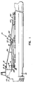
- Figure 1 is a side view of a ship having a preferred embodiment of an articulated boom mechanism in accordance with this invention extending on its deck;
- Figure 2 is a perspective view of that end of the preferred embodiment of the articulated boom mechanism that is mounted to the structure of the ship;
- Figure 3 is a side view of that end of the preferred embodiment of the articulated boom mechanism that is mounted to the structure of the ship, the view also illustrating an over-hanging structure through which material is conveyed from the hold or holds of the ship;
- Figure 4 is a side view of the articulation member of the preferred embodiment of the articulated boom mechanism, the articulation member having first and second boom members pivotally connected to it;
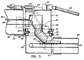
- Figure 5 is a sectional side view of the articulation member and first and second boom members of Figure 4;
- Figure 6 is an enlarged view of that portion of Figure 5 relating to the annular bearing that is secured between the upper and lower portions of the articulation member;
- Figure 7 is a sectional perspective view of the annular bearing that is secured between the upper and lower portions of the articulation member; and
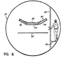
- Figure 8 is a diametrical cross-sectional view of the first boom member of the preferred embodiment of the articulated boom mechanism.
- With reference to Figure 1,
ship 10 has a series of holds extending serially along its length, each hold being capable of holding a portion of a bulk solid material cargo. A series of belts terminating inbelt 11, illustrated in outline in Figure 1, transports bulk solid material from the holds to overhangstructure 12, that structure extending forward of the raisedsuperstructure 13 at the rear ofship 10. The bulk solid material is emptied frombelt 11 as that belt moves withinoverhang structure 12 and falls through a flexiblecylindrical hood 14 into the base of the articulated boom mechanism, that mechanism being generally designated 15. -
Articulated boom mechanism 15 is supported onship 10 by abase structure 20 mounted on the deck ofship 10 and by an overhang member 21 extending forward of raisedsuperstructure 13 and aboveoverhang structure 12. With reference to Figure 2,base structure 20 has a sloped lower portion and a generally rectangular upper portion, with a pair ofhydraulic piston chambers 22 extending from each of an opposite pair of sides of the rectangular upper portion. Each facing pair ofhydraulic piston chambers 22 contains a piston (not shown) connected to an opposite end of acommon rack member 23, hydraulic fluid entering one of the facing pair ofchambers 22 moving therack member 23 in one direction while hydraulic fluid is being expelled to a reservoir from the other one of the chambers. The hydraulic fluid is forced simultaneously into a diagonally-opposite pair of thechambers 22 such that the pair of rack -members 23 move simultaneously an equal distance but in opposed directions. Centered between the pair ofrack members 23 is apinion member 24 having teeth on its periphery which engage the teeth of the pair ofrack members 23.Pinion member 24 is mounted on bearings for free rotation and has a spline groove 25 machined into its inner periphery. Aturret member 27 with an integral splined shaft is mounted onpinion member 24 such that its spline sits in spline groove 25. A pair oftrunnions 28 are integral withturret member 27 and extend from an opposite pair of sides ofturret member 27. Thechambers 22,rack 23,pinion member 24 andtrunnion 28 form first powered pivot means. - Mounted to rotate in the pair of
trunnions 28 is afirst boom member 30, its one end being pivotally mounted to the pair oftrunnions 28 and its other end being connected by first actuator means in the form ofhydraulic actuator mechanism 31 to overhang member 21. The supporting connection betweenhydraulic actuator mechanism 31 and overhang member 21 is by means of a universal joint 32 such that rotation is possible around an axis normal to the deck of the ship and one parallel to the deck. Axle assembly 32 allowshydraulic actuator mechanism 31 to rotate withfirst boom member 30. As best shown in Figure 4,hydraulic actuator mechanism 31 is pivotally connected to the outer end offirst boom member 30 by aflange 33 extending from that outer end. -
First boom member 30 is a circular tube having a diameter of 10.5 feet (3.20 metres). The tube is formed of steel and has 0.375 inch (0.95 cm) thick walls. Circular reinforcing hoops of rectangular cross-section (not shown) are secured to the outside of the circular tube approximately every 10 feet (3.04 metres) along the length of the tube; the reinforcing hoops resist torsional stress placed ontofirst boom member 30.Thick steel bands first boom member 30 to distribute over the tube the load exerted by the pair oftrunnions 28 andhydraulic actuator mechanism 31. In the illustrated preferred embodiment,first boom member 30 is approximately 130 feet (39.62 metres) in length. - An
articulation member 40, as best shown in Figures 4 and 5, has anupper portion 41 and alower portion 42 pivotally connected toupper portion 41.Articulation member 40 is itself pivotally connected to the outer end offirst boom member 30 by a pair oftrunnions 43. Aflange 44 secured to the top ofarticulation member 40 is connected by further actuator means in the form ofhydraulic actuator mechanism 45, to theflange 33 onfirst boom member 30.Hydraulic actuator mechanisms hydraulic actuator mechanism 31 results in a corresponding contraction or expansion ofhydraulic actuator mechanism 45, the effect being thatarticulation member 40 maintains a constant orientation relative to the deck of the ship for all angular positions offirst boom member 30; the orientation is one in which the axis of rotation between theupper portion 41 and thelower portion 42 ofarticulation member 40 extends normal to the deck of the ship. -
Articulation member 40 in plan view is circular in cross-section, thelower portion 42 being rotatable relative to theupper portion 41 by means of an annular bearing generally designated 50.Annular bearing 50 is of the type found on large cranes and is capable of carrying very heavy loading forces while still allowing the two portions ofarticulation member 40 to rotate relative to each other. Figure 6 illustratesannular bearing 50 in an enlarged sectioned side view, while Figure 7 illustrates a perspective sectioned view of the bearing. An upperannular frame 51 of rectangular cross-section and a corresponding lowerannular frame 52 are secured to respective upper and lowercomplementary bearing members rollers 55 each of which has its axis of rotation oriented normal to the axis of rotation of its immediately-adjacent neighbours extends in a diamond-shapedrace 56 defined by the facing surfaces of bearingmembers - As illustrated in Figures 5 and 6, a series of
motors 57 are mounted to the periphery of upperannular frame 51. Each motor has agear wheel 58 secured to its rotor, the series ofgear wheels 58 having teeth that engage with complementary teeth on aring gear 59 that extends around the periphery of lowerannular frame 52. This arrangement (50, 57, 58, 59) forms second powered pivot means. Themotors 57 are electrically connected such that all are actuated simultaneously; such actuation results in thelower portion 42 ofarticulation member 40 and a connectedsecond boom member 60 rotating relative to theupper portion 41 ofarticulation member 40. - The
second boom member 60 has its inner end pivotally mounted by a pair oftrunnions 61 to thelower portion 42 ofarticulation member 40, as shown in Figure 1.Second boom member 60 is of rectangular cross-section and is formed from steel plate 0.375 inch (0.95 cm) thick.Member 60 of the preferred embodiment is approximately 90 feet (27.43 metres) long, and is 10.5 feet (3.20 metres) wide and 6.5 feet (1.98 metres) high. As withfirst boom member 30,second boom member 60 has hoops of rectangular cross-section (not shown) secured around its periphery at intervals of approximately 10 feet (3.04 metres) to assist in resisting torsional stresses. Second actuator means in the form of ahydraulic actuator mechanism 62, are connected between aflange 63 extending fromarticulation member 40 and aflange 64 secured tosecond boom member 60. Similar to the arrangement withhydraulic actuator mechanism 31,hydraulic actuator mechanism 62 has its one end mounted through a universal joint to flange 63 so asto allow it to rotate with thelower portion 42 ofarticulation member 40 and withsecond boom member 60. - A
first conveyor belt 67 is mounted to extend centrally throughfirst boom member 30, and asecond conveyor belts 68 is mounted to extend centerally throughsecond boom member 60, as illustrated in Figure 5. One of the two end rollers 82 around whichbelt 67 extends is mounted so as to have its axis of rotation extending generally concentrically with the pivot axis around whicharticulation member 60 rotates relative tofirst boom member 30. This arrangement allows bulksolid material 70 being carried onbelt 67 to consistently fall onto the inner surface of achute 72 secured to theupper portion 41 ofarticulation member 40. Thematerial 70 is guided bychute 72 and empties ontobelt 68 ofsecond boom member 60, guide surfaces 73 secured tomember 60 preventing material from falling from the sides ofbelt 68. The lower lip ofchute 72 sits abovebelt 68 approximately above the axis through whichsecond boom member 60 is pivoted to thelower portion 42 ofarticulation member 40. That arrangement allows the lower lip ofchute 72 to maintain its small spacing frombelt 68 over all relative angular orientations betweensecond boom member 60 andarticulation member 40. - Figure 8 illustrates a diametrical cross-sectional view of
first boom member 30.Belt 67 can be seen to be supported by three rollers, a horizontalcentral roller 77 and an adjacent pair ofinclined side rollers 78. Near either end offirst boom member 30, theside rollers 78 assume a horizontal orientation withcentral roller 77, as illustrated in Figure 5; a similar situation is true with respect toboom member 60. As seen in Figure 8, a walkway for personnel is formed by a verticalstructural element 80 and a connecting horizontal floor surface 81. - The position of the outer end of
second boom member 60, from which bulk solid material leaves the articulated boom mechanism, is positioned by selective actuation ofhydraulic actuator mechanisms chambers 22, and selective actuation of themotors 57. It will be appreciated that the articulated boom mechanism of this invention will allow a ship to be emptied both faster and more easily than is possible with a single span unloading boom.
Claims (11)
characterized by:
whereby bulk solid material placed onto one of the conveyor means is subsequently discharged from the other conveyor means after moving through a path determined by the first and second actuator means (31, 62) and the first and second pivot means.
Priority Applications (1)
| Application Number | Priority Date | Filing Date | Title |
|---|---|---|---|
| AT86304511T ATE60016T1 (en) | 1985-06-14 | 1986-06-12 | SWIVEL ARM FOR UNLOADING A SHIP OF SOLID BULK GOODS. |
Applications Claiming Priority (4)
| Application Number | Priority Date | Filing Date | Title |
|---|---|---|---|
| CA000484002A CA1218330A (en) | 1985-06-14 | 1985-06-14 | Articulated boom mechanism for unloading bulk solid material from a ship |
| CA484002 | 1985-06-14 | ||
| US06/861,680 US4712962A (en) | 1985-06-14 | 1986-05-09 | Articulated boom mechanism for unloading bulk solid material from a ship |
| US861680 | 1986-05-09 |
Publications (3)
| Publication Number | Publication Date |
|---|---|
| EP0206660A2 EP0206660A2 (en) | 1986-12-30 |
| EP0206660A3 EP0206660A3 (en) | 1988-01-13 |
| EP0206660B1 true EP0206660B1 (en) | 1991-01-16 |
Family
ID=25670712
Family Applications (1)
| Application Number | Title | Priority Date | Filing Date |
|---|---|---|---|
| EP86304511A Expired - Lifetime EP0206660B1 (en) | 1985-06-14 | 1986-06-12 | Articulated boom mechanism for unloading bulk solid material from a ship |
Country Status (6)
| Country | Link |
|---|---|
| EP (1) | EP0206660B1 (en) |
| CN (1) | CN86103989B (en) |
| AU (1) | AU580672B2 (en) |
| BR (1) | BR8602755A (en) |
| DE (1) | DE3676886D1 (en) |
| FI (1) | FI86394C (en) |
Families Citing this family (3)
| Publication number | Priority date | Publication date | Assignee | Title |
|---|---|---|---|---|
| DE102009016082A1 (en) * | 2008-04-28 | 2009-10-29 | Stefan Leske | Device for safely transferring personnel or material from a ship-shaped object to a relatively moved object and ship with the device |
| CN104340604A (en) * | 2014-10-30 | 2015-02-11 | 黄繁昌 | Turnable conveying device for ships |
| ES2568748B1 (en) * | 2014-11-03 | 2017-02-08 | BSH Electrodomésticos España S.A. | Cooking Field Device |
Family Cites Families (3)
| Publication number | Priority date | Publication date | Assignee | Title |
|---|---|---|---|---|
| DD47489A (en) * | ||||
| DD80631A (en) * | ||||
| DD72699A (en) * |
-
1986
- 1986-06-10 AU AU58491/86A patent/AU580672B2/en not_active Ceased
- 1986-06-12 FI FI862522A patent/FI86394C/en not_active IP Right Cessation
- 1986-06-12 DE DE8686304511T patent/DE3676886D1/en not_active Expired - Lifetime
- 1986-06-12 EP EP86304511A patent/EP0206660B1/en not_active Expired - Lifetime
- 1986-06-12 BR BR8602755A patent/BR8602755A/en not_active IP Right Cessation
- 1986-06-13 CN CN86103989A patent/CN86103989B/en not_active Expired
Also Published As
| Publication number | Publication date |
|---|---|
| FI862522L (en) | 1986-12-15 |
| DE3676886D1 (en) | 1991-02-21 |
| CN86103989B (en) | 1988-12-28 |
| FI862522A0 (en) | 1986-06-12 |
| AU580672B2 (en) | 1989-01-27 |
| AU5849186A (en) | 1986-12-18 |
| BR8602755A (en) | 1987-02-10 |
| CN86103989A (en) | 1987-04-01 |
| FI86394C (en) | 1992-08-25 |
| EP0206660A2 (en) | 1986-12-30 |
| EP0206660A3 (en) | 1988-01-13 |
| FI86394B (en) | 1992-05-15 |
Similar Documents
| Publication | Publication Date | Title |
|---|---|---|
| US5203442A (en) | Cantilever conveying techniques | |
| US4020953A (en) | Apparatus for unloading particulate material, especially from ships | |
| US4712962A (en) | Articulated boom mechanism for unloading bulk solid material from a ship | |
| US5634545A (en) | Apparatus for continuously conveying coal from a continuous mining machine to a remote floor conveyor | |
| US6622846B1 (en) | Aircraft cargo loader | |
| JPH0416380B2 (en) | ||
| JPS6224323B2 (en) | ||
| US4284369A (en) | Take-up head for bulk material conveyor installation | |
| EP0000550A1 (en) | Vertical bulk-conveying apparatus and bulk delivering system utilizing the characteristics thereof | |
| US5191966A (en) | Apparatus and method for unloading bulk materials | |
| JPS6143280B2 (en) | ||
| EP0362306B1 (en) | Cargo conveyor system | |
| EP0206660A2 (en) | Articulated boom mechanism for unloading bulk solid material from a ship | |
| CA1250246A (en) | Apparatus and method for unloading bulk materials | |
| GB2124585A (en) | Lift crane | |
| US5335780A (en) | Multi-direction package movement device | |
| US4379672A (en) | Combination handling and conveying apparatus | |
| US4957198A (en) | Apparatus and method for unloading bulk materials | |
| CA1104515A (en) | Offloading installation for ships, bunkers, stockyards or the like | |
| US4738350A (en) | Apparatus for unloading bulk materials | |
| US20140048343A1 (en) | Multi-axis articulating crawler | |
| US5197843A (en) | Device for loading and unloading unitary cargo onto and from ships | |
| JPS61221018A (en) | Excavating and cargo lifting device | |
| CA1309684C (en) | Cargo conveyor system | |
| KR101661153B1 (en) | Tracked moving apparatus |
Legal Events
| Date | Code | Title | Description |
|---|---|---|---|
| PUAI | Public reference made under article 153(3) epc to a published international application that has entered the european phase |
Free format text: ORIGINAL CODE: 0009012 |
|
| AK | Designated contracting states |
Kind code of ref document: A2 Designated state(s): AT BE CH DE FR GB IT LI LU NL SE |
|
| PUAL | Search report despatched |
Free format text: ORIGINAL CODE: 0009013 |
|
| AK | Designated contracting states |
Kind code of ref document: A3 Designated state(s): AT BE CH DE FR GB IT LI LU NL SE |
|
| 17P | Request for examination filed |
Effective date: 19880708 |
|
| 17Q | First examination report despatched |
Effective date: 19890613 |
|
| ITF | It: translation for a ep patent filed | ||
| GRAA | (expected) grant |
Free format text: ORIGINAL CODE: 0009210 |
|
| AK | Designated contracting states |
Kind code of ref document: B1 Designated state(s): AT BE CH DE FR GB IT LI LU NL SE |
|
| PG25 | Lapsed in a contracting state [announced via postgrant information from national office to epo] |
Ref country code: LI Effective date: 19910116 Ref country code: CH Effective date: 19910116 Ref country code: BE Effective date: 19910116 Ref country code: AT Effective date: 19910116 |
|
| REF | Corresponds to: |
Ref document number: 60016 Country of ref document: AT Date of ref document: 19910215 Kind code of ref document: T |
|
| REF | Corresponds to: |
Ref document number: 3676886 Country of ref document: DE Date of ref document: 19910221 |
|
| ET | Fr: translation filed | ||
| REG | Reference to a national code |
Ref country code: CH Ref legal event code: PL |
|
| PG25 | Lapsed in a contracting state [announced via postgrant information from national office to epo] |
Ref country code: LU Free format text: LAPSE BECAUSE OF NON-PAYMENT OF DUE FEES Effective date: 19910630 |
|
| PLBE | No opposition filed within time limit |
Free format text: ORIGINAL CODE: 0009261 |
|
| STAA | Information on the status of an ep patent application or granted ep patent |
Free format text: STATUS: NO OPPOSITION FILED WITHIN TIME LIMIT |
|
| 26N | No opposition filed | ||
| EAL | Se: european patent in force in sweden |
Ref document number: 86304511.8 |
|
| PGFP | Annual fee paid to national office [announced via postgrant information from national office to epo] |
Ref country code: FR Payment date: 20010611 Year of fee payment: 16 |
|
| PGFP | Annual fee paid to national office [announced via postgrant information from national office to epo] |
Ref country code: NL Payment date: 20010628 Year of fee payment: 16 |
|
| REG | Reference to a national code |
Ref country code: GB Ref legal event code: IF02 |
|
| PG25 | Lapsed in a contracting state [announced via postgrant information from national office to epo] |
Ref country code: NL Free format text: LAPSE BECAUSE OF NON-PAYMENT OF DUE FEES Effective date: 20030101 |
|
| PG25 | Lapsed in a contracting state [announced via postgrant information from national office to epo] |
Ref country code: FR Free format text: LAPSE BECAUSE OF NON-PAYMENT OF DUE FEES Effective date: 20030228 |
|
| NLV4 | Nl: lapsed or anulled due to non-payment of the annual fee |
Effective date: 20030101 |
|
| REG | Reference to a national code |
Ref country code: FR Ref legal event code: ST |
|
| PGFP | Annual fee paid to national office [announced via postgrant information from national office to epo] |
Ref country code: SE Payment date: 20040604 Year of fee payment: 19 |
|
| PGFP | Annual fee paid to national office [announced via postgrant information from national office to epo] |
Ref country code: GB Payment date: 20040609 Year of fee payment: 19 |
|
| PGFP | Annual fee paid to national office [announced via postgrant information from national office to epo] |
Ref country code: DE Payment date: 20040624 Year of fee payment: 19 |
|
| PG25 | Lapsed in a contracting state [announced via postgrant information from national office to epo] |
Ref country code: IT Free format text: LAPSE BECAUSE OF NON-PAYMENT OF DUE FEES;WARNING: LAPSES OF ITALIAN PATENTS WITH EFFECTIVE DATE BEFORE 2007 MAY HAVE OCCURRED AT ANY TIME BEFORE 2007. THE CORRECT EFFECTIVE DATE MAY BE DIFFERENT FROM THE ONE RECORDED. Effective date: 20050612 Ref country code: GB Free format text: LAPSE BECAUSE OF NON-PAYMENT OF DUE FEES Effective date: 20050612 |
|
| PG25 | Lapsed in a contracting state [announced via postgrant information from national office to epo] |
Ref country code: SE Free format text: LAPSE BECAUSE OF NON-PAYMENT OF DUE FEES Effective date: 20050613 |
|
| PG25 | Lapsed in a contracting state [announced via postgrant information from national office to epo] |
Ref country code: DE Free format text: LAPSE BECAUSE OF NON-PAYMENT OF DUE FEES Effective date: 20060103 |
|
| EUG | Se: european patent has lapsed | ||
| GBPC | Gb: european patent ceased through non-payment of renewal fee |
Effective date: 20050612 |