EP0206433A2 - Methods for measuring the light absorbance of a fluid medium - Google Patents
Methods for measuring the light absorbance of a fluid medium Download PDFInfo
- Publication number
- EP0206433A2 EP0206433A2 EP86201107A EP86201107A EP0206433A2 EP 0206433 A2 EP0206433 A2 EP 0206433A2 EP 86201107 A EP86201107 A EP 86201107A EP 86201107 A EP86201107 A EP 86201107A EP 0206433 A2 EP0206433 A2 EP 0206433A2
- Authority
- EP
- European Patent Office
- Prior art keywords
- prism
- light
- constituent
- probe
- medium
- Prior art date
- Legal status (The legal status is an assumption and is not a legal conclusion. Google has not performed a legal analysis and makes no representation as to the accuracy of the status listed.)
- Granted
Links
Images


Classifications
-
- G—PHYSICS
- G01—MEASURING; TESTING
- G01N—INVESTIGATING OR ANALYSING MATERIALS BY DETERMINING THEIR CHEMICAL OR PHYSICAL PROPERTIES
- G01N21/00—Investigating or analysing materials by the use of optical means, i.e. using sub-millimetre waves, infrared, visible or ultraviolet light
- G01N21/17—Systems in which incident light is modified in accordance with the properties of the material investigated
- G01N21/55—Specular reflectivity
- G01N21/552—Attenuated total reflection
-
- G—PHYSICS
- G01—MEASURING; TESTING
- G01N—INVESTIGATING OR ANALYSING MATERIALS BY DETERMINING THEIR CHEMICAL OR PHYSICAL PROPERTIES
- G01N21/00—Investigating or analysing materials by the use of optical means, i.e. using sub-millimetre waves, infrared, visible or ultraviolet light
- G01N21/17—Systems in which incident light is modified in accordance with the properties of the material investigated
- G01N21/25—Colour; Spectral properties, i.e. comparison of effect of material on the light at two or more different wavelengths or wavelength bands
- G01N21/31—Investigating relative effect of material at wavelengths characteristic of specific elements or molecules, e.g. atomic absorption spectrometry
- G01N21/33—Investigating relative effect of material at wavelengths characteristic of specific elements or molecules, e.g. atomic absorption spectrometry using ultraviolet light
-
- G—PHYSICS
- G01—MEASURING; TESTING
- G01N—INVESTIGATING OR ANALYSING MATERIALS BY DETERMINING THEIR CHEMICAL OR PHYSICAL PROPERTIES
- G01N21/00—Investigating or analysing materials by the use of optical means, i.e. using sub-millimetre waves, infrared, visible or ultraviolet light
- G01N21/84—Systems specially adapted for particular applications
- G01N21/85—Investigating moving fluids or granular solids
- G01N21/8507—Probe photometers, i.e. with optical measuring part dipped into fluid sample
-
- G—PHYSICS
- G01—MEASURING; TESTING
- G01N—INVESTIGATING OR ANALYSING MATERIALS BY DETERMINING THEIR CHEMICAL OR PHYSICAL PROPERTIES
- G01N2201/00—Features of devices classified in G01N21/00
- G01N2201/08—Optical fibres; light guides
Definitions
- This invention relates to the measurement of concentrations of light absorbing constituents of fluid mediums. It is particularly useful for in-situ analyses of mediums having high absorbance characteristics.
- UV absorption spectroscopy in the ultraviolet (UV) wavelength range is a widely used method for analysis of organic materials which absorb UV radiation. Due to the high absorbtivities (i.e., large extinction coefficients) of UV absorbing compounds, absorbtion measurements customarily are performed on samples diluted with UV transparent solvents. Dilution factors of 100 to 10,000 .commonly are employed iri conjunction with absorption cells having pathlengths of from 1 mm to 10 cm. Absorption measurements of undiluted samples would require the use of cells with pathlengths on the order of 1 micrometer. The necessity of either diluting the sample or employing absorption cells of inconveniently short pathlengths has severely limited the application of UV absorption spectroscopy for in-situ analyses in chemical processes.
- the concentrations of light absorbing constituents of a fluid medium are determined by the use of a fiber optic probe having two groups of optical fibers optically coupled to a transparent prism whose refractive index exceeds that of the medium to be analyzed.
- One group of fibers is used to transmit light to a prism having a wavelength that can be absorbed by a particular.constituent of the fluid medium.
- the prism has at least two angularly displaced, adjacent faces in contact with the medium.
- the light undergoes successive attenuated total internal reflections and emerges from the prism via the second group of optical fibers which transmit the reflected light outwardly of the probe to an apparatus which measures the intensities of the reflected light at one or more wavelengths.
- the measured values of the intensities thus obtained are compared with corresponding values obtained in the same way using like mediums, but containing known concentrations of the constituent, thereby enabling the concentration of the absorbing constituent in the medium under analysis to be determined.
- the invention is predicated on the concept that, when light traveling within a medium impinges upon a boundary between that medium and a medium of lower refractive index, it either passes into the second medium or is totally internally reflected, n depending on whether the quantity n' sin I (where n and n' are the refractive indices of the first and second mediums, respectively, and I is the angle of incidence) is less than or greater than one. If n n' sin I is greater than one, total internal reflection occurs. Although the internal reflection is referred to as a total, the light, during the reflection process, penetrates a short distance into the second medium.
- the depth of penetration depends in a complex and known manner on the refractive indices of the two mediums and the angle of incidence, but usually is on the order of tenths of the wavelength of the light. If the incident light includes a wavelength absorbed by a constituent of the second medium, light of such wavelength will be partially absorbed or attenuated during reflection due to the penetration of the light into the second medium.
- ATR attenuated total reflection Due to the very shallow penetration of the light into the second medium, ATR is a useful technique for measuring absorbance by strongly absorbing materials.
- the refractive index of the prism exceed that of the medium limits the choice of prism materials.
- silica 1.51 at 250 nm
- Silica is useful only for samples of relatively low refractive index, such as aqueous solutions.
- Diamond is very expensive and does not transmit wavelengths below 225 nm.
- sapphire is the most useful material for ATR measurements in the UV range.
- In-situ ATR measurements conveniently can be made according to the invention by the use of a probe having a hollow housing formed of material that can be immersed in a fluid medium containing a constituent capable of absorbing light of a specific wavelength.
- Light of preferably substantially constant intensity is conducted from a source remote from the medium via one or more optical fibers to one end of the probe.
- a prism having a plurality of angularly displaced, adjacent faces in contact with the medium.
- Light transmitted to the probe is totally internally reflected from the first face of the prism to each other face thereof in succession and from the last face to one or more optical fibers which conduct the reflected light out of the probe to an apparatus for measuring its intensity.
- the absorbing constituent in the medium will absorb some of the light, thereby reducing its intensity.
- the intensity of light transmitted by the probe at wavelengths absorbed by a constituent thus is inversely related to the concentration of that constituent.
- the apparatus may be calibrated by immersing the probe in two or more calibrating mediums and measuring in each case the intensity of the transmitted light at a wavelength absorbed by a particular constituent in each medium.
- the calibrating mediums correspond to that to be analyzed, but contain known concentrations of the light absorbing constituent.
- the apparatus then may be used in a like manner to measure the intensity of transmitted light following immersion of the probe in a like medium containing a like constituent of unknown concentration.
- the intensities obtained from the calibrating mediums and the medium under analysis may be compared to obtain the concentration of the absorbing constituent in the latter medium.
- the effective path of the light in a medium being analyzed is approximately proportional to N/cos I, where N is the number of reflections and I is the angle of incidence.
- a probe 1 according to the embodiment of Figure 1 has a hollow body 2 formed of metal or other material suitable for immersion in a chemical process fluid that is to be analyzed. Each end of the body is closed except for openings 3 which accommodate known clad optical fibers. In this embodiment there are three fibers 4, 5, and 6, respectively, fixed in the openings 3, but there can be as few as two such fibers diametrally opposite one another. At one end of the body is an external groove 7 which accommodates a sealing ring 8 that encircles the openings 3. Seated on the sealing ring is a trapezoidal prism 9 formed of a high refractive index material, such as sapphire. Between the prism and the confronting ends of the optical fibers is an optical coupling gel or oil 9a. A clamp 10 maintains the prism in place at the end of the probe and is secured to the body screws 11.
- the prism has a flat base 12 and three external faces 13, 14, and 15.
- one of the optical fibers that extends from the probe body 2 is coupled to a substantially constant intensity light source 16 that is remote from the probe.
- the light source may be a deuterium lamp if light in the UV range is to be used.
- the fiber 4 is coupled to the light source and such fiber hereinafter will be referred to as the input fiber.
- the other two fibers 5 and 6 shown in Figures 2 and 7 will be referred to hereinafter as output fibers.
- the output fiber 5 is optically coupled to a silicon diode detector 17 via a bandpass filter 18 and the output fiber 6 also is coupled to a similar detector 19 via a bandpass filter 20.
- the filters isolate two discrete, different wavelengths.
- the outputs from the detectors 17 and 19 are amplified by trans-impedance amplifiers 21 and 22, respectively, and transmitted to a computer 23 which measures the intensities of the respective wavelengths and computes the concentration of the associated constituent.-In the embodiment shown in Figures 1, 2, and 7, that end of the probe 1 from which the prism 9 projects is immersed in a fluid medium 24 containing a constituent that will absorb light of a particular wavelength.
- the light emitted by the source 16 includes the particular wavelength absorbable by the constituent and is conducted by the input fiber 4 to the base 12 of the prism 9 along a path that is normal to the base.
- Light emitted from the input fiber diverges as it traverses the optical path through the prism. The overall length of such optical path is so selected as to illuminate both of the output fibers 5 and 6 from.the single input fiber.
- the signal from the detector 17 constitutes a calibration signal. If the filter 20 transmits light of a frequency absorbed by the constituent, then the signal from the detector 19 will vary inversely with the concentration of the absorbing constituent. The ratio of the respective signals, as determined by the computer, enables the concentration of the absorbing constituent to be determined.
- each output fiber be illuminated fully. It is desirable to minimize the length of the optical path in the prism because of the divergence of the transmitted light and the consequent reduction of its intensity.
- FIG. 4 illustrates a probe having three input fibers 24a and three output fibers 25a. Light emitted from each of the input fibers will illuminate more than one of the output fibers. Thus, a construction having three input fibers and three output fibers may transmit as much as four to eight times as much light as a two-fiber probe and. enable the analysis of the concentrations of multiple constituents simultaneously.
- Figure 3 illustrates an embodiment of the invention which differs from the others in that the input and output optical fibers 26a and 27a are inclined with respect to the probe axis by an angle of 10 to 30° and converge in a direction toward a prism 28a.
- the base angles are reduced appropriately. This results in an increase in the angle of incidence and thus allows the probe to operate in mediums of higher refractive index.
- the angle of incidence if given by
- a probe according to Figure 3 may include a sapphire prism and quartz fibers with an angle of 30° between the fiber axes and the probe axis. Such a probe has an angle of incidence of about 68°. It is thus useful in analyzing materials having refractive indices as high as 1.71 at 250 nm.
- Figure 5 shows a prism 30 having a base 31 and four faces 32, 33, 34, and 35 which produce four reflections.
- the angles of incidence and the base angles are 67.5°.
- the prism 36 of Figure 6 has a base 37 and five faces 38, 39, 40, 41, and 42 which produce five reflections.
- the angles of incidence and the base angles are 72°.
- Probes producing four and five reflections also can be constructed with fibers that are parallel to the probe axis. Such a probe having five reflecting surfaces, and its fiber axes inclined 30° with respect to the probe axis, has angles of incidence of about 77°. Thus it is useful in samples with refractive indices up to about 1.79 at 250 nm.
- Probes with larger angles of incidence and larger numbers of reflecting surfaces could be constructed, but these would not increase significantly the range of refractive indices inasmuch as the ultimate limit is 1.84, i.e., the refractive index of the sapphire prism material.
- the optical fibers should have relatively large core diameters. Fibers with core diameters of about 0.6 mm are preferred because larger fibers are more expensive and difficult to handle due to their large bending radii. It is desirable to minimize the length of the optical path in the prism because of the divergence of the transmitted light and the consequent reduction in its intensity.
- the light transmission can be increased by the use of multiple fibers to conduct light to and from the prism.
- the amount of light conducted to the prism is proportional to the total surface area of the fiber ends, i.e., to the product of the cross sectional area of one fiber and the number of input fibers.
- Standard deuterium lamps with apertures of 1 mm can fully illuminate three fibers with core diameters of 0.6 mm and a numerical aperture of 0.25.
- a probe according to Figure 4 could have its output fibers 25 coupled to three filter-detector systems of the kind shown in Figure 7 for measuring the transmittance at three different wavelengths, thus allowing simultaneous measurements of the concentrations of two components.
- the output fibers of any of the probes can be arranged linearly as shown in Figure 8 and coupled to a spectrophotometer 46 for scanning a spectrum.
- Systems can be constructed to allow analyses of samples with three or more components.
Landscapes
- Physics & Mathematics (AREA)
- Health & Medical Sciences (AREA)
- Life Sciences & Earth Sciences (AREA)
- Chemical & Material Sciences (AREA)
- Analytical Chemistry (AREA)
- Biochemistry (AREA)
- General Health & Medical Sciences (AREA)
- General Physics & Mathematics (AREA)
- Immunology (AREA)
- Pathology (AREA)
- Investigating Or Analysing Materials By Optical Means (AREA)
Abstract
Description
- This invention relates to the measurement of concentrations of light absorbing constituents of fluid mediums. It is particularly useful for in-situ analyses of mediums having high absorbance characteristics.
- Absorption spectroscopy in the ultraviolet (UV) wavelength range is a widely used method for analysis of organic materials which absorb UV radiation. Due to the high absorbtivities (i.e., large extinction coefficients) of UV absorbing compounds, absorbtion measurements customarily are performed on samples diluted with UV transparent solvents. Dilution factors of 100 to 10,000 .commonly are employed iri conjunction with absorption cells having pathlengths of from 1 mm to 10 cm. Absorption measurements of undiluted samples would require the use of cells with pathlengths on the order of 1 micrometer. The necessity of either diluting the sample or employing absorption cells of inconveniently short pathlengths has severely limited the application of UV absorption spectroscopy for in-situ analyses in chemical processes.
- The concentrations of light absorbing constituents of a fluid medium are determined by the use of a fiber optic probe having two groups of optical fibers optically coupled to a transparent prism whose refractive index exceeds that of the medium to be analyzed. One group of fibers is used to transmit light to a prism having a wavelength that can be absorbed by a particular.constituent of the fluid medium. The prism has at least two angularly displaced, adjacent faces in contact with the medium. Within the prism the light undergoes successive attenuated total internal reflections and emerges from the prism via the second group of optical fibers which transmit the reflected light outwardly of the probe to an apparatus which measures the intensities of the reflected light at one or more wavelengths. The measured values of the intensities thus obtained are compared with corresponding values obtained in the same way using like mediums, but containing known concentrations of the constituent, thereby enabling the concentration of the absorbing constituent in the medium under analysis to be determined.
- Figure 1 is a fragmentary, vertical sectional view taken on line 1-1 of Figure 2 and illustrating a probe according to one embodiment of the invention;
- Figure 2 is a top plan view of the probe shown in Figure 1;
- Figure 3 is a diagrammatic view similar to Figure 1, but illustrating a second embodiment;
- Figure 4 is a view similar to-Figure 2, but illustrating a further embodiment;
- Figures 5 and 6 are diagrammatic views illustrating other forms of prisms which may be used with the probes;
- Figure 7 is a diagrammatic view illustrating apparatus required for performing the process according to one embodiment; and
- Figure 8 is a view similar to Figure 7, but illustrating a modified embodiment of the apparatus.
- The invention is predicated on the concept that, when light traveling within a medium impinges upon a boundary between that medium and a medium of lower refractive index, it either passes into the second medium or is totally internally reflected, n depending on whether the quantity n' sin I (where n and n' are the refractive indices of the first and second mediums, respectively, and I is the angle of incidence) is less than or greater than one. If n n' sin I is greater than one, total internal reflection occurs. Although the internal reflection is referred to as a total, the light, during the reflection process, penetrates a short distance into the second medium. The depth of penetration depends in a complex and known manner on the refractive indices of the two mediums and the angle of incidence, but usually is on the order of tenths of the wavelength of the light. If the incident light includes a wavelength absorbed by a constituent of the second medium, light of such wavelength will be partially absorbed or attenuated during reflection due to the penetration of the light into the second medium.
- This effect is called attenuated total reflection (ATR). Due to the very shallow penetration of the light into the second medium, ATR is a useful technique for measuring absorbance by strongly absorbing materials.
- The requirement that the refractive index of the prism exceed that of the medium limits the choice of prism materials. For use in the mid-ultraviolet region (200-300 nm wavelengths), only silica (n = 1.51 at 250 nm), sapphire (n = 1.84 at 250 nm), and diamond (n = 2.7 at 250 nm) have sufficiently high refractive indices and transmissions to be useful. Silica is useful only for samples of relatively low refractive index, such as aqueous solutions. Diamond is very expensive and does not transmit wavelengths below 225 nm. Thus, sapphire is the most useful material for ATR measurements in the UV range.
- In-situ ATR measurements conveniently can be made according to the invention by the use of a probe having a hollow housing formed of material that can be immersed in a fluid medium containing a constituent capable of absorbing light of a specific wavelength. Light of preferably substantially constant intensity is conducted from a source remote from the medium via one or more optical fibers to one end of the probe. At the other end of the probe is a prism having a plurality of angularly displaced, adjacent faces in contact with the medium. Light transmitted to the probe is totally internally reflected from the first face of the prism to each other face thereof in succession and from the last face to one or more optical fibers which conduct the reflected light out of the probe to an apparatus for measuring its intensity. Each time the light is reflected within the prism, the absorbing constituent in the medium will absorb some of the light, thereby reducing its intensity. The intensity of light transmitted by the probe at wavelengths absorbed by a constituent thus is inversely related to the concentration of that constituent.
- The apparatus may be calibrated by immersing the probe in two or more calibrating mediums and measuring in each case the intensity of the transmitted light at a wavelength absorbed by a particular constituent in each medium. The calibrating mediums correspond to that to be analyzed, but contain known concentrations of the light absorbing constituent. The apparatus then may be used in a like manner to measure the intensity of transmitted light following immersion of the probe in a like medium containing a like constituent of unknown concentration. The intensities obtained from the calibrating mediums and the medium under analysis may be compared to obtain the concentration of the absorbing constituent in the latter medium.
- . The effective path of the light in a medium being analyzed is approximately proportional to N/cos I, where N is the number of reflections and I is the angle of incidence. The upper limit of the refractive index (n') of the fluid medium is given by the formula n' = n sin I, where n is the refractive index of the prism material. Since the choice of the prism materials is limited, it is convenient to vary the angle of incidence and/or the number of reflections to accommodate samples of various refractive indices and absorbtivities.
- A probe 1 according to the embodiment of Figure 1 has a
hollow body 2 formed of metal or other material suitable for immersion in a chemical process fluid that is to be analyzed. Each end of the body is closed except for openings 3 which accommodate known clad optical fibers. In this embodiment there are threefibers ring 8 that encircles the openings 3. Seated on the sealing ring is atrapezoidal prism 9 formed of a high refractive index material, such as sapphire. Between the prism and the confronting ends of the optical fibers is an optical coupling gel or oil 9a. Aclamp 10 maintains the prism in place at the end of the probe and is secured to the body screws 11. The prism has aflat base 12 and threeexternal faces - To condition the apparatus thus far described for use, one of the optical fibers that extends from the
probe body 2 is coupled to a substantially constantintensity light source 16 that is remote from the probe. The light source may be a deuterium lamp if light in the UV range is to be used. As shown in Figure 7 thefiber 4 is coupled to the light source and such fiber hereinafter will be referred to as the input fiber. The other twofibers 5 and 6 shown in Figures 2 and 7 will be referred to hereinafter as output fibers. - The
output fiber 5 is optically coupled to asilicon diode detector 17 via abandpass filter 18 and the output fiber 6 also is coupled to asimilar detector 19 via abandpass filter 20. The filters isolate two discrete, different wavelengths. The outputs from thedetectors impedance amplifiers computer 23 which measures the intensities of the respective wavelengths and computes the concentration of the associated constituent.-In the embodiment shown in Figures 1, 2, and 7, that end of the probe 1 from which theprism 9 projects is immersed in afluid medium 24 containing a constituent that will absorb light of a particular wavelength. The light emitted by thesource 16, includes the particular wavelength absorbable by the constituent and is conducted by theinput fiber 4 to thebase 12 of theprism 9 along a path that is normal to the base. Light enters the prism and is transmitted along apath 25 which impinges on theface 13 at an angle of incidence which effects total internal reflection of the light along apath 26 to theface 14 where total internal reflection again occurs to cause the light to travel along apath 27 to theface 15 where once again the light is totally reflected along apath 28 toward theprism base 12. Light emitted from the input fiber diverges as it traverses the optical path through the prism. The overall length of such optical path is so selected as to illuminate both of theoutput fibers 5 and 6 from.the single input fiber. - Assuming that the.
filter 18 transmits light of a wavelength not absorbed by any constituent of the medium, then the signal from thedetector 17 constitutes a calibration signal. If thefilter 20 transmits light of a frequency absorbed by the constituent, then the signal from thedetector 19 will vary inversely with the concentration of the absorbing constituent. The ratio of the respective signals, as determined by the computer, enables the concentration of the absorbing constituent to be determined. P - It is not necessary that two output fibers be used; one is sufficient. However, the use of two output fibers enables the calibration and the concentration procedures to be conducted simultaneously, whereas if a single output fiber were used the calibration would-require the immersion of the probe in a medium corresponding to the medium 24, but from which the absorbing constituent has been omitted. In this instance the values of the calibrating and the other intensities have to be determined sequentially and then compared.
- For the process according to the invention to function reliably, it is necessary that each output fiber be illuminated fully. It is desirable to minimize the length of the optical path in the prism because of the divergence of the transmitted light and the consequent reduction of its intensity.
- It is not necessary that the probe'be limited to a single input fiber or to one or two output fibers.- Figure 4 illustrates a probe having three
input fibers 24a and three output fibers 25a. Light emitted from each of the input fibers will illuminate more than one of the output fibers. Thus, a construction having three input fibers and three output fibers may transmit as much as four to eight times as much light as a two-fiber probe and. enable the analysis of the concentrations of multiple constituents simultaneously. - Figure 3 illustrates an embodiment of the invention which differs from the others in that the input and output optical fibers 26a and 27a are inclined with respect to the probe axis by an angle of 10 to 30° and converge in a direction toward a
prism 28a. The base angles are reduced appropriately. This results in an increase in the angle of incidence and thus allows the probe to operate in mediums of higher refractive index. - If the refractive index of the prism shown in Figure 3 is different from that of the optical fibers, light will be refracted on entering and leaving the prism. The angle x' between the axis of the optical path entering the prism and the p-robe axis is related to the angle x between the fiber n* axis and the probe axis by the relation sin x' = n sin x, where n* is the refractive index of the fiber and n is the refractive index of the prism. The angle of incidence if given by
-
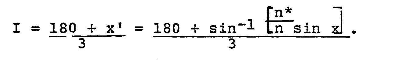
- A probe according to Figure 3 may include a sapphire prism and quartz fibers with an angle of 30° between the fiber axes and the probe axis. Such a probe has an angle of incidence of about 68°. It is thus useful in analyzing materials having refractive indices as high as 1.71 at 250 nm.
- The number of reflections to which the transmitted light is subjected is not limited to two or three. Figure 5 shows a
prism 30 having a base 31 and four faces 32, 33, 34, and 35 which produce four reflections. The angles of incidence and the base angles are 67.5°. Theprism 36 of Figure 6 has abase 37 and five faces 38, 39, 40, 41, and 42 which produce five reflections. The angles of incidence and the base angles are 72°. - Probes producing four and five reflections also can be constructed with fibers that are parallel to the probe axis. Such a probe having five reflecting surfaces, and its fiber axes inclined 30° with respect to the probe axis, has angles of incidence of about 77°. Thus it is useful in samples with refractive indices up to about 1.79 at 250 nm.
- Probes with larger angles of incidence and larger numbers of reflecting surfaces could be constructed, but these would not increase significantly the range of refractive indices inasmuch as the ultimate limit is 1.84, i.e., the refractive index of the sapphire prism material.
- For many applications, it is desirable to maximize the light transmissions through the prism. For maximum light transmission the optical fibers should have relatively large core diameters. Fibers with core diameters of about 0.6 mm are preferred because larger fibers are more expensive and difficult to handle due to their large bending radii. It is desirable to minimize the length of the optical path in the prism because of the divergence of the transmitted light and the consequent reduction in its intensity.
- The light transmission can be increased by the use of multiple fibers to conduct light to and from the prism. Within limits imposed by the size and aperture angle of the light source, the amount of light conducted to the prism is proportional to the total surface area of the fiber ends, i.e., to the product of the cross sectional area of one fiber and the number of input fibers. Standard deuterium lamps with apertures of 1 mm can fully illuminate three fibers with core diameters of 0.6 mm and a numerical aperture of 0.25.
- A probe according to Figure 4 could have its
output fibers 25 coupled to three filter-detector systems of the kind shown in Figure 7 for measuring the transmittance at three different wavelengths, thus allowing simultaneous measurements of the concentrations of two components. Alternatively, the output fibers of any of the probes can be arranged linearly as shown in Figure 8 and coupled to aspectrophotometer 46 for scanning a spectrum. Systems can be constructed to allow analyses of samples with three or more components.
Claims (12)
Applications Claiming Priority (2)
| Application Number | Priority Date | Filing Date | Title |
|---|---|---|---|
| US74865785A | 1985-06-25 | 1985-06-25 | |
| US748657 | 1985-06-25 |
Publications (3)
| Publication Number | Publication Date |
|---|---|
| EP0206433A2 true EP0206433A2 (en) | 1986-12-30 |
| EP0206433A3 EP0206433A3 (en) | 1989-10-18 |
| EP0206433B1 EP0206433B1 (en) | 1993-05-05 |
Family
ID=25010375
Family Applications (1)
| Application Number | Title | Priority Date | Filing Date |
|---|---|---|---|
| EP86201107A Expired - Lifetime EP0206433B1 (en) | 1985-06-25 | 1986-06-24 | Methods for measuring the light absorbance of a fluid medium |
Country Status (5)
| Country | Link |
|---|---|
| US (1) | US4829186A (en) |
| EP (1) | EP0206433B1 (en) |
| JP (1) | JPS622138A (en) |
| CA (1) | CA1273223A (en) |
| DE (1) | DE3688380T2 (en) |
Cited By (21)
| Publication number | Priority date | Publication date | Assignee | Title |
|---|---|---|---|---|
| DE3806881A1 (en) * | 1988-03-03 | 1989-09-07 | Kostal Leopold Gmbh & Co Kg | Sensor device |
| US5046854A (en) * | 1990-02-01 | 1991-09-10 | The Dow Chemical Company | Photometric cell and probe having windows fusion sealed to a metallic body |
| EP0417700A3 (en) * | 1989-09-12 | 1991-12-04 | The State Of Israel Atomic Energy Commission Soreq Nuclear Research Center | Improvement in attenuated total reflection spectroscopy |
| GB2255200A (en) * | 1991-04-26 | 1992-10-28 | British Tech Group | Prismatic probe head for attenuated total reflection spectroscopy |
| DE4418180A1 (en) * | 1994-06-27 | 1996-01-25 | Emmrich Roland | Spectral absorption measuring device |
| FR2737571A1 (en) * | 1995-08-04 | 1997-02-07 | Telecommunications Sa | Optical probe for spectroscopic analysis of materials - using a rod formed of transparent material connected to an inlet-outlet coupling |
| US5926269A (en) * | 1995-06-14 | 1999-07-20 | Dystar Textilfarben Gmbh & Co. | Optical probe with sensor made of optical polymer |
| DE19856591A1 (en) * | 1998-12-08 | 2000-06-21 | Basf Ag | Arrangement for attenuated reflected light spectroscopy for monitoring chromophoric intermediates has a fiber optics and prism arrangement and means to measure intensity of the light beam reflected by prism/liquid interface |
| DE10214780A1 (en) * | 2002-04-03 | 2003-10-30 | Univ Jw Goethe Frankfurt Main | Infrared spectrometry device, especially for the spectrometry of aqueous systems, comprises an attenuated total reflection body and an infrared source with the ATR body configured to provide total internal reflection |
| DE10257716A1 (en) * | 2002-12-11 | 2004-07-08 | Institut für Textilchemie der Deutschen Institute für Textil- und Faserforschung Stuttgart | Optical sensor for determining dye concentrations in liquid media and method for its operation |
| EP1583955A1 (en) * | 2003-01-07 | 2005-10-12 | The Lubrizol Corporation | Apparatus for on-line monitoring quality/condition of fluids |
| EP1444502A4 (en) * | 2001-10-11 | 2007-05-09 | Sentelligence Inc | Low-cost on-line and in-line spectral sensors based on solid-state source and detector combinations for monitoring lubricants and functional fluids |
| DE102006036409A1 (en) * | 2006-04-06 | 2007-10-18 | Endress + Hauser Conducta Gesellschaft für Mess- und Regeltechnik mbH + Co. KG | Attenuated total internal reflection probe for testing measuring medium, has transparent radiation guiding body with front surfaces connected with each other by circumferential mantel surface of clamping body |
| DE102006056867A1 (en) * | 2006-12-01 | 2008-06-12 | Deutsche Institute für Textil- und Faserforschung Denkendorf (DITF) Institut für Textilchemie und Chemiefasern (ITCF) | Sensor for determining concentration of materials contained in fluid or gaseous medium, has measuring head comprises comprise of transmitter unit emitting transmission light beams and receiver unit has semiconductor receiver element |
| US7459713B2 (en) | 2003-08-14 | 2008-12-02 | Microptix Technologies, Llc | Integrated sensing system approach for handheld spectral measurements having a disposable sample handling apparatus |
| EP0801736B1 (en) * | 1994-05-13 | 2009-03-11 | Sensir Technologies, LLC | Crystal assembly for measuring attenuated total reflection of infrared radiation |
| DE102007058611A1 (en) | 2007-12-04 | 2009-06-10 | Endress + Hauser Conducta Gesellschaft für Mess- und Regeltechnik mbH + Co. KG | ATR probe |
| US7812312B2 (en) | 2002-04-03 | 2010-10-12 | Johann Wolfgang Goethe-Universitaet | Infrared measuring device, especially for the spectrometry of aqueous systems, preferably multiple component systems |
| DE102011085615A1 (en) * | 2010-11-09 | 2012-07-12 | Endress + Hauser Conducta Gesellschaft für Mess- und Regeltechnik mbH + Co. KG | Attenuated total reflection probe for investigation of liquid medium by optical radiation, has guide body comprising end faces, where optical radiation is coupled such that angle of specific degrees with regard to optical axis |
| WO2018005465A1 (en) * | 2016-06-29 | 2018-01-04 | General Electric Company | Apparatus and method for analyzing composition in oil and gas production well |
| US12073924B2 (en) | 2018-03-02 | 2024-08-27 | Genzyme Corporation | Multivariate spectral analysis and monitoring for biomanufacturing |
Families Citing this family (33)
| Publication number | Priority date | Publication date | Assignee | Title |
|---|---|---|---|---|
| JPS63274840A (en) * | 1987-05-06 | 1988-11-11 | Hamamatsu Photonics Kk | Process supervisory and controlling equipment |
| JP2797311B2 (en) * | 1988-03-29 | 1998-09-17 | 株式会社島津製作所 | Total reflection absorption spectrum measurement device |
| US5170056A (en) * | 1991-02-28 | 1992-12-08 | Galileo Electro-Optics Corporation | Optical fiber coupled devices for remote spectroscopy in the infrared |
| US5200609A (en) * | 1991-08-27 | 1993-04-06 | Sting Donald W | Radiant energy spectroscopy system with diamond internal reflection element |
| EP0624785B1 (en) * | 1992-10-07 | 1998-11-25 | Sumitomo Electric Industries, Ltd. | Infrared optical part and measuring instrument |
| US5436454A (en) * | 1993-10-15 | 1995-07-25 | Nicolet Instrument Corporation | Optical probe for remote attenuated total reflectance measurements |
| GB9415962D0 (en) * | 1994-08-06 | 1994-09-28 | Schlumberger Ltd | Multiphase fluid component discrimination |
| US5724151A (en) * | 1995-08-04 | 1998-03-03 | E.I. Du Pont De Nemours And Company | Waveguide sensing element for use in a sample medium and method of rear-firing electromagnetic radiation |
| US6118520A (en) * | 1996-12-18 | 2000-09-12 | The Dow Chemical Company | Dual analysis probe |
| US5991029A (en) * | 1998-04-06 | 1999-11-23 | Axiom Analytical, Inc. | Attenuated total reflecance probe employing large incidence angles |
| DE10007818A1 (en) * | 2000-02-21 | 2001-08-23 | Mahrt Karl Heinz | High pressure capability compact precision measurement head, has pressure protected area where received beam is evaluated, and front section having volume of 0.5 cubic millimeter |
| US7390669B2 (en) * | 2000-02-24 | 2008-06-24 | Georgia Tech Research Corporation | Simultaneous and rapid determination of multiple component concentrations in a Kraft liquor process stream |
| CA2434983A1 (en) * | 2001-01-23 | 2002-08-01 | Dublin City University | A luminescence based sensor |
| US6690452B2 (en) * | 2001-04-18 | 2004-02-10 | Paul A. Wilks, Jr. | Monitor having a polymer internal reflective element |
| SE524900C2 (en) * | 2002-07-22 | 2004-10-19 | Senseair Ab | Gas analyzing arrangements |
| US6954560B2 (en) * | 2002-12-30 | 2005-10-11 | Advanced Technology Materials, Inc. | Attenuated total reflection spectroscopic analysis of organic additives in metal plating solutions |
| US7382458B2 (en) * | 2004-04-01 | 2008-06-03 | Custom Sample Systems, Inc. | Fiber optic fluid probe |
| AU2006264210B2 (en) * | 2005-06-27 | 2010-07-22 | Colin Jeffress | Spectroscopic lance for bulk sampling |
| WO2007000018A1 (en) * | 2005-06-27 | 2007-01-04 | Colin Jeffress | Spectroscopic lance for bulk sampling |
| US7978331B2 (en) * | 2006-03-16 | 2011-07-12 | Kurashiki Boseki Kabushiki Kaisha | Attenuated total reflection optical probe and apparatus therewith for spectroscopic measurement of aqueous solution |
| JP4958220B2 (en) * | 2006-03-16 | 2012-06-20 | 倉敷紡績株式会社 | Total reflection attenuation optical probe and aqueous solution spectrometer using the same |
| US20080144033A1 (en) * | 2006-12-13 | 2008-06-19 | Scully Signal Company | Optical level detection probe for fluid overfill prevention system |
| JP4911606B2 (en) * | 2007-03-08 | 2012-04-04 | 倉敷紡績株式会社 | Total reflection attenuation optical probe and aqueous solution spectrometer using the same |
| KR20110040851A (en) * | 2008-07-30 | 2011-04-20 | 가부시키가이샤 호리바 어드밴스트 테크노 | Silicon concentration measuring device |
| US20110228278A1 (en) * | 2008-11-11 | 2011-09-22 | Kathryn Lee | Uv-vis atr short pathlength spectroscopy of printing inks |
| FI124114B (en) * | 2009-09-29 | 2014-03-31 | Janesko Oy | The measuring window Structure |
| WO2015052893A1 (en) * | 2013-10-11 | 2015-04-16 | Dic株式会社 | Atr element, immersion probe, and spectrophotometer |
| JP5861855B1 (en) * | 2014-02-20 | 2016-02-16 | Dic株式会社 | Photometer and method for monitoring synthetic reaction process |
| EP3026422B1 (en) | 2014-11-26 | 2018-02-14 | Universität Stuttgart | An apparatus and a method for spectroscopic ellipsometry, in particular infrared spectroscopic ellipsometry |
| JP6217674B2 (en) * | 2015-03-13 | 2017-10-25 | 横河電機株式会社 | Transmission probe, optical apparatus, and liquid permeation overmeasurement method |
| CN109073455A (en) | 2016-03-07 | 2018-12-21 | Ysi公司 | Optical nitrate sensor for multiparameter water quality measurement |
| GB201611651D0 (en) * | 2016-07-04 | 2016-08-17 | Element Six Tech Ltd | An attenuated total reflection crystal fabricated from diamond material |
| US20220386875A1 (en) * | 2019-10-28 | 2022-12-08 | Yoshihiro Oba | Measuring apparatus and biological information measuring apparatus |
Family Cites Families (9)
| Publication number | Priority date | Publication date | Assignee | Title |
|---|---|---|---|---|
| DE2121744A1 (en) * | 1971-05-03 | 1972-11-09 | Siemens Ag | Optoelectronic device for measuring and controlling the concentration of solutions |
| US3917410A (en) * | 1971-07-28 | 1975-11-04 | Helmut Ulrich | Apparatus for measuring the refractive index of liquids or gases |
| US3733130A (en) * | 1972-03-07 | 1973-05-15 | Atomic Energy Commission | Slotted probe for spectroscopic measurements |
| FR2317638A1 (en) * | 1975-07-09 | 1977-02-04 | Commissariat Energie Atomique | SYSTEM FOR ANALYSIS OF THE CONSTITUENTS OF A SOLUTION BY PHOTOMETRIC MEASUREMENT |
| DE2809910C2 (en) * | 1978-03-08 | 1986-06-26 | Diessel Gmbh & Co, 3200 Hildesheim | Method for the quantitative determination of constituents of beer |
| CH652825A5 (en) * | 1980-09-18 | 1985-11-29 | Battelle Memorial Institute | DUAL OPTICAL PROBE DEVICE FOR DETERMINING THE REFRACTION INDEX OF A FLUID RETURNED TO A PREDETERMINED REFERENCE TEMPERATURE. |
| JPS57111435A (en) * | 1980-12-27 | 1982-07-10 | Horiba Ltd | Measuring device for absorption intensity of infrared ray by atr method |
| FI65143C (en) * | 1981-12-23 | 1984-03-12 | Valtion Teknillinen | MAETHUVUD FOER INFRAROEDHYGROMETER |
| US4602869A (en) * | 1983-12-05 | 1986-07-29 | Harrick Nicolas J | Internal reflection prism liquid cell |
-
1986
- 1986-06-24 DE DE8686201107T patent/DE3688380T2/en not_active Expired - Fee Related
- 1986-06-24 EP EP86201107A patent/EP0206433B1/en not_active Expired - Lifetime
- 1986-06-24 JP JP61146295A patent/JPS622138A/en active Pending
- 1986-06-24 CA CA000512256A patent/CA1273223A/en not_active Expired - Fee Related
-
1988
- 1988-06-28 US US07/214,902 patent/US4829186A/en not_active Expired - Lifetime
Cited By (35)
| Publication number | Priority date | Publication date | Assignee | Title |
|---|---|---|---|---|
| DE3806881A1 (en) * | 1988-03-03 | 1989-09-07 | Kostal Leopold Gmbh & Co Kg | Sensor device |
| EP0417700A3 (en) * | 1989-09-12 | 1991-12-04 | The State Of Israel Atomic Energy Commission Soreq Nuclear Research Center | Improvement in attenuated total reflection spectroscopy |
| US5046854A (en) * | 1990-02-01 | 1991-09-10 | The Dow Chemical Company | Photometric cell and probe having windows fusion sealed to a metallic body |
| GB2255200A (en) * | 1991-04-26 | 1992-10-28 | British Tech Group | Prismatic probe head for attenuated total reflection spectroscopy |
| GB2255200B (en) * | 1991-04-26 | 1994-07-13 | British Tech Group | Prismatic probe heads for attenuated total reflectance spectroscopy |
| EP0801736B1 (en) * | 1994-05-13 | 2009-03-11 | Sensir Technologies, LLC | Crystal assembly for measuring attenuated total reflection of infrared radiation |
| DE4418180A1 (en) * | 1994-06-27 | 1996-01-25 | Emmrich Roland | Spectral absorption measuring device |
| US5926269A (en) * | 1995-06-14 | 1999-07-20 | Dystar Textilfarben Gmbh & Co. | Optical probe with sensor made of optical polymer |
| FR2737571A1 (en) * | 1995-08-04 | 1997-02-07 | Telecommunications Sa | Optical probe for spectroscopic analysis of materials - using a rod formed of transparent material connected to an inlet-outlet coupling |
| US6535283B1 (en) | 1998-12-08 | 2003-03-18 | Basf Aktiengesellschaft | Apparatus for spectroscopic analysis of a fluid medium by attenuated reflection |
| DE19856591C2 (en) * | 1998-12-08 | 2001-03-08 | Basf Ag | Device for the spectroscopic analysis of a fluid medium by means of attenuated reflection |
| DE19856591A1 (en) * | 1998-12-08 | 2000-06-21 | Basf Ag | Arrangement for attenuated reflected light spectroscopy for monitoring chromophoric intermediates has a fiber optics and prism arrangement and means to measure intensity of the light beam reflected by prism/liquid interface |
| EP1444502A4 (en) * | 2001-10-11 | 2007-05-09 | Sentelligence Inc | Low-cost on-line and in-line spectral sensors based on solid-state source and detector combinations for monitoring lubricants and functional fluids |
| US7339657B2 (en) | 2001-10-11 | 2008-03-04 | Sentelligence, Inc. | Low-cost on-line and in-line spectral sensors based on solid-state source and detectors combinations for monitoring lubricants and functional fluids |
| US7812312B2 (en) | 2002-04-03 | 2010-10-12 | Johann Wolfgang Goethe-Universitaet | Infrared measuring device, especially for the spectrometry of aqueous systems, preferably multiple component systems |
| DE10214780A1 (en) * | 2002-04-03 | 2003-10-30 | Univ Jw Goethe Frankfurt Main | Infrared spectrometry device, especially for the spectrometry of aqueous systems, comprises an attenuated total reflection body and an infrared source with the ATR body configured to provide total internal reflection |
| DE10257716A1 (en) * | 2002-12-11 | 2004-07-08 | Institut für Textilchemie der Deutschen Institute für Textil- und Faserforschung Stuttgart | Optical sensor for determining dye concentrations in liquid media and method for its operation |
| DE10257716B4 (en) * | 2002-12-11 | 2005-12-29 | Institut für Textilchemie der Deutschen Institute für Textil- und Faserforschung Stuttgart | Optical sensor for the determination of dye concentrations in liquid media and method for its operation |
| US7359055B2 (en) | 2002-12-11 | 2008-04-15 | Institut fur Textilchemie der Deutschen Institute fur Textil-und Faserforschung Stuttgart | Optical sensor for determining the concentrations of dyes and/or particles in liquid or gaseous media and method for operating the same |
| EP1583955A1 (en) * | 2003-01-07 | 2005-10-12 | The Lubrizol Corporation | Apparatus for on-line monitoring quality/condition of fluids |
| AU2004204512B2 (en) * | 2003-01-07 | 2008-11-06 | The Lubrizol Corporation | Apparatus for on-line monitoring quality/condition of fluids |
| US7907282B2 (en) | 2003-08-14 | 2011-03-15 | Microptix Technologies, Llc | Integrated sensing module for handheld spectral measurements |
| US7459713B2 (en) | 2003-08-14 | 2008-12-02 | Microptix Technologies, Llc | Integrated sensing system approach for handheld spectral measurements having a disposable sample handling apparatus |
| DE102006036409A1 (en) * | 2006-04-06 | 2007-10-18 | Endress + Hauser Conducta Gesellschaft für Mess- und Regeltechnik mbH + Co. KG | Attenuated total internal reflection probe for testing measuring medium, has transparent radiation guiding body with front surfaces connected with each other by circumferential mantel surface of clamping body |
| DE102006036409B4 (en) * | 2006-04-06 | 2011-06-22 | Endress + Hauser Conducta Gesellschaft für Mess- und Regeltechnik mbH + Co. KG, 70839 | ATR probe for analyzing a medium with infrared radiation |
| DE102006056867B4 (en) * | 2006-12-01 | 2008-10-16 | Deutsche Institute für Textil- und Faserforschung Denkendorf (DITF) Institut für Textilchemie und Chemiefasern (ITCF) | Method for carrying out wastewater analyzes by means of a sensor |
| DE102006056867A1 (en) * | 2006-12-01 | 2008-06-12 | Deutsche Institute für Textil- und Faserforschung Denkendorf (DITF) Institut für Textilchemie und Chemiefasern (ITCF) | Sensor for determining concentration of materials contained in fluid or gaseous medium, has measuring head comprises comprise of transmitter unit emitting transmission light beams and receiver unit has semiconductor receiver element |
| DE102007058611A1 (en) | 2007-12-04 | 2009-06-10 | Endress + Hauser Conducta Gesellschaft für Mess- und Regeltechnik mbH + Co. KG | ATR probe |
| WO2009071557A3 (en) * | 2007-12-04 | 2009-10-15 | Endress+Hauser Conducta Gesellschaft Für Mess- Und Regeltechnik Mbh+Co. Kg | Atr probe |
| CN101889195B (en) * | 2007-12-04 | 2013-05-22 | 恩德莱斯和豪瑟尔测量及调节技术分析仪表两合公司 | Atr probe |
| DE102011085615A1 (en) * | 2010-11-09 | 2012-07-12 | Endress + Hauser Conducta Gesellschaft für Mess- und Regeltechnik mbH + Co. KG | Attenuated total reflection probe for investigation of liquid medium by optical radiation, has guide body comprising end faces, where optical radiation is coupled such that angle of specific degrees with regard to optical axis |
| DE102011085615B4 (en) | 2010-11-09 | 2024-08-22 | Endress+Hauser Conducta Gmbh+Co. Kg | ATR probe for examining a medium using optical radiation |
| WO2018005465A1 (en) * | 2016-06-29 | 2018-01-04 | General Electric Company | Apparatus and method for analyzing composition in oil and gas production well |
| US12073924B2 (en) | 2018-03-02 | 2024-08-27 | Genzyme Corporation | Multivariate spectral analysis and monitoring for biomanufacturing |
| US12205680B2 (en) | 2018-03-02 | 2025-01-21 | Genzyme Corporation | Multivariate spectral analysis and monitoring for biomanufacturing |
Also Published As
| Publication number | Publication date |
|---|---|
| DE3688380T2 (en) | 1993-08-12 |
| CA1273223A (en) | 1990-08-28 |
| DE3688380D1 (en) | 1993-06-09 |
| JPS622138A (en) | 1987-01-08 |
| US4829186A (en) | 1989-05-09 |
| EP0206433B1 (en) | 1993-05-05 |
| EP0206433A3 (en) | 1989-10-18 |
Similar Documents
| Publication | Publication Date | Title |
|---|---|---|
| EP0206433B1 (en) | Methods for measuring the light absorbance of a fluid medium | |
| US5410413A (en) | Optical head probe using a gradient index lens and optical fibers | |
| US8107067B2 (en) | Opaque additive to block stray light in teflon AF light-guiding flowcells | |
| US6535283B1 (en) | Apparatus for spectroscopic analysis of a fluid medium by attenuated reflection | |
| US3604927A (en) | Total reflection fluorescence spectroscopy | |
| JP2763770B2 (en) | Light scattering characteristics measurement method | |
| US4699511A (en) | Refraction sensor | |
| US4678326A (en) | Apparatus for the measurement of fluorescence, turbidity, luminescence or absorption | |
| US5239176A (en) | Tapered optical fiber sensing attenuated total reflectance | |
| US5181082A (en) | On-line titration using colorimetric end point detection | |
| US5381237A (en) | Multi-purpose optical head probe | |
| KR870003385A (en) | Analysis method of solution and dispersion | |
| US5416579A (en) | Method for determining concentration in a solution using attenuated total reflectance spectrometry | |
| JPH03120443A (en) | Convergent light optoroad | |
| EP0494524A2 (en) | Monitoring device | |
| US4181441A (en) | Internal reflectance spectrometer | |
| US3733130A (en) | Slotted probe for spectroscopic measurements | |
| US5070243A (en) | Attenuated total reflection spectroscopy | |
| Brown et al. | Interfacing a fiber-optic probe to a diode array UV-visible spectrophotometer for drug dissolution tests | |
| US3247758A (en) | Dual monochromator system | |
| DE3024061C2 (en) | Refractometer | |
| JP3895434B2 (en) | Tubular attenuated lightwave sensor for molecular absorption spectroscopy | |
| JP2004205415A (en) | Optical analysis measurement probe device, solution concentration monitoring method, and spectroscopic analyzer | |
| Schlemmer et al. | ATR technique for UV/VIS analytical measurements | |
| WO2005100955A1 (en) | Method and apparatus for determining the absorption of weakly absorbing and/or scattering liquid samples |
Legal Events
| Date | Code | Title | Description |
|---|---|---|---|
| PUAI | Public reference made under article 153(3) epc to a published international application that has entered the european phase |
Free format text: ORIGINAL CODE: 0009012 |
|
| AK | Designated contracting states |
Kind code of ref document: A2 Designated state(s): DE FR GB NL |
|
| PUAL | Search report despatched |
Free format text: ORIGINAL CODE: 0009013 |
|
| RHK1 | Main classification (correction) |
Ipc: G01N 21/55 |
|
| AK | Designated contracting states |
Kind code of ref document: A3 Designated state(s): DE FR GB NL |
|
| 17P | Request for examination filed |
Effective date: 19900418 |
|
| 17Q | First examination report despatched |
Effective date: 19910710 |
|
| RTI1 | Title (correction) | ||
| GRAA | (expected) grant |
Free format text: ORIGINAL CODE: 0009210 |
|
| AK | Designated contracting states |
Kind code of ref document: B1 Designated state(s): DE FR GB NL |
|
| REF | Corresponds to: |
Ref document number: 3688380 Country of ref document: DE Date of ref document: 19930609 |
|
| ET | Fr: translation filed | ||
| PLBE | No opposition filed within time limit |
Free format text: ORIGINAL CODE: 0009261 |
|
| STAA | Information on the status of an ep patent application or granted ep patent |
Free format text: STATUS: NO OPPOSITION FILED WITHIN TIME LIMIT |
|
| 26N | No opposition filed | ||
| REG | Reference to a national code |
Ref country code: GB Ref legal event code: IF02 |
|
| PGFP | Annual fee paid to national office [announced via postgrant information from national office to epo] |
Ref country code: FR Payment date: 20030312 Year of fee payment: 18 |
|
| PGFP | Annual fee paid to national office [announced via postgrant information from national office to epo] |
Ref country code: NL Payment date: 20030314 Year of fee payment: 18 |
|
| PGFP | Annual fee paid to national office [announced via postgrant information from national office to epo] |
Ref country code: GB Payment date: 20030331 Year of fee payment: 18 |
|
| PGFP | Annual fee paid to national office [announced via postgrant information from national office to epo] |
Ref country code: DE Payment date: 20030527 Year of fee payment: 18 |
|
| PG25 | Lapsed in a contracting state [announced via postgrant information from national office to epo] |
Ref country code: GB Free format text: LAPSE BECAUSE OF NON-PAYMENT OF DUE FEES Effective date: 20040624 |
|
| PG25 | Lapsed in a contracting state [announced via postgrant information from national office to epo] |
Ref country code: NL Free format text: LAPSE BECAUSE OF NON-PAYMENT OF DUE FEES Effective date: 20050101 Ref country code: DE Free format text: LAPSE BECAUSE OF NON-PAYMENT OF DUE FEES Effective date: 20050101 |
|
| GBPC | Gb: european patent ceased through non-payment of renewal fee |
Effective date: 20040624 |
|
| PG25 | Lapsed in a contracting state [announced via postgrant information from national office to epo] |
Ref country code: FR Free format text: LAPSE BECAUSE OF NON-PAYMENT OF DUE FEES Effective date: 20050228 |
|
| NLV4 | Nl: lapsed or anulled due to non-payment of the annual fee |
Effective date: 20050101 |
|
| REG | Reference to a national code |
Ref country code: FR Ref legal event code: ST |