EP0206271B1 - Apparatus for control of number of idling rotations of internal combustion engines - Google Patents
Apparatus for control of number of idling rotations of internal combustion engines Download PDFInfo
- Publication number
- EP0206271B1 EP0206271B1 EP86108407A EP86108407A EP0206271B1 EP 0206271 B1 EP0206271 B1 EP 0206271B1 EP 86108407 A EP86108407 A EP 86108407A EP 86108407 A EP86108407 A EP 86108407A EP 0206271 B1 EP0206271 B1 EP 0206271B1
- Authority
- EP
- European Patent Office
- Prior art keywords
- engine
- control
- rotations
- control valve
- idling
- Prior art date
- Legal status (The legal status is an assumption and is not a legal conclusion. Google has not performed a legal analysis and makes no representation as to the accuracy of the status listed.)
- Expired
Links
- 238000002485 combustion reaction Methods 0.000 title claims description 9
- 230000003247 decreasing effect Effects 0.000 claims description 2
- 238000012545 processing Methods 0.000 description 11
- 238000010586 diagram Methods 0.000 description 7
- 238000000034 method Methods 0.000 description 5
- 230000007423 decrease Effects 0.000 description 3
- 239000000446 fuel Substances 0.000 description 3
- 230000010354 integration Effects 0.000 description 3
- 230000004044 response Effects 0.000 description 3
- 238000002347 injection Methods 0.000 description 2
- 239000007924 injection Substances 0.000 description 2
- 239000007858 starting material Substances 0.000 description 2
- 238000011144 upstream manufacturing Methods 0.000 description 2
- 238000010276 construction Methods 0.000 description 1
- 238000007796 conventional method Methods 0.000 description 1
- 239000000498 cooling water Substances 0.000 description 1
- 238000012937 correction Methods 0.000 description 1
- 230000000694 effects Effects 0.000 description 1
- 230000001771 impaired effect Effects 0.000 description 1
- 238000005259 measurement Methods 0.000 description 1
- 239000000203 mixture Substances 0.000 description 1
- 230000000246 remedial effect Effects 0.000 description 1
- 239000000243 solution Substances 0.000 description 1
Images


Classifications
-
- F—MECHANICAL ENGINEERING; LIGHTING; HEATING; WEAPONS; BLASTING
- F02—COMBUSTION ENGINES; HOT-GAS OR COMBUSTION-PRODUCT ENGINE PLANTS
- F02D—CONTROLLING COMBUSTION ENGINES
- F02D31/00—Use of speed-sensing governors to control combustion engines, not otherwise provided for
- F02D31/001—Electric control of rotation speed
- F02D31/002—Electric control of rotation speed controlling air supply
- F02D31/003—Electric control of rotation speed controlling air supply for idle speed control
- F02D31/005—Electric control of rotation speed controlling air supply for idle speed control by controlling a throttle by-pass
-
- F—MECHANICAL ENGINEERING; LIGHTING; HEATING; WEAPONS; BLASTING
- F02—COMBUSTION ENGINES; HOT-GAS OR COMBUSTION-PRODUCT ENGINE PLANTS
- F02D—CONTROLLING COMBUSTION ENGINES
- F02D11/00—Arrangements for, or adaptations to, non-automatic engine control initiation means, e.g. operator initiated
- F02D11/06—Arrangements for, or adaptations to, non-automatic engine control initiation means, e.g. operator initiated characterised by non-mechanical control linkages, e.g. fluid control linkages or by control linkages with power drive or assistance
- F02D11/10—Arrangements for, or adaptations to, non-automatic engine control initiation means, e.g. operator initiated characterised by non-mechanical control linkages, e.g. fluid control linkages or by control linkages with power drive or assistance of the electric type
- F02D2011/101—Arrangements for, or adaptations to, non-automatic engine control initiation means, e.g. operator initiated characterised by non-mechanical control linkages, e.g. fluid control linkages or by control linkages with power drive or assistance of the electric type characterised by the means for actuating the throttles
- F02D2011/102—Arrangements for, or adaptations to, non-automatic engine control initiation means, e.g. operator initiated characterised by non-mechanical control linkages, e.g. fluid control linkages or by control linkages with power drive or assistance of the electric type characterised by the means for actuating the throttles at least one throttle being moved only by an electric actuator
Definitions
- This invention relates to an apparatus for the control of the number of idling rotations of an internal combustion engine (hereinafter referred to simply as "engine"), and more particularly to an apparatus for the control of the number of idling rotations of the engine, adapted so that when the number of rotations of the engine under closed-loop control falls below the lower limit of the prescribed range of idling rotations, the engine is shifted to the open-loop control mode and the number of engine rotations is quickly increased to within the prescribed range of idling rotation numbers.
- engine internal combustion engine
- the exciting current fed to a solenoid which proportionately controls the opening area of the control valve is adapted to be fixed in accordance with the solenoid current command Icmd to be obtained by the following formula (1).
- lfb(n) represents the term of PID feedback control for effecting proportional (P term), integral (I term), and differential (D term) control based on the difference between the target number of idling rotations and the existing number of engine rotations.
- the coefficients (control gains) of the P term, I term, and D term are fixed at relatively small levels, while the degree of opening of the control valve is subjected to the feedback control based on the PID feedback control term. This is because the stability of the number of idling rotations during the steady idle operation is rather impaired when the control gains are too large.
- a possible stall condition is determined based on monitored engine performance, including engine speed and rate of change of engine speed, and an anti-stall procedure is initiated based on this determination.
- the procedure involves engine load-shedding, such as switching-off an air-conditioner or other non-essential appliances alternatively using the starter motor or alternator to provide extra torque to the engine.
- the degree of load-shedding is limited by the power consumed by the appliances, which are switched off and therefore not all stall conditions can be prevented by load-shedding.
- the use of the starter motor or alternator as additional power sources contributes to increased wear and reduced service life of these appliances.
- DE-OS-30 17 846 discloses a further method and apparatus for controlling an internal combustion engine in which the rate of air supply to the engine is controlled either by a feedback control system or an open-loop control system.
- the decision as to which control system is used depends on engine conditions including engine speed.
- This known system has the disadvantage that abrupt changes in engine speed may occur too quickly for the change from closed to open-loop control or vice versa to be effected.
- This problem is partly solved by introducing a delay time between control system changes, which however reduces the overall response time of the system.
- the air flow is set to a single value, so that if the change to open loop control is used close to a stall condition this single value is maintained and no further remedial action is carried out.
- This invention has been produced to solve the problems mentioned above.
- the solution of these problems resides in providing an apparatus for the control of the number of idling rotations of an internal combustion engine, including a control valve to control an amount of inspired air in said internal combustion engine during an idle operation thereof by proportionately controlling a degree of opening of said control valve in accordance with the a control valve command,
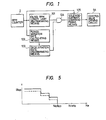
- Fig. 2 is a schematic structural diagram illustrating a typical apparatus for the control of the number of idling rotations (RPM) of an engine as one embodiment of this invention.
- the amount of inspired air in an intake manifold 33 during an idle operation wherein a throttle valve 32 remains in a substantially completely closed state is controlled by a control valve 30 disposed in a bypass 31 which communicates with the upstream and downstream sides of the throttle valve 32.
- This control valve 30 has the degree of opening or the position thereof fixed in proportion to the magnitude of electric current flowing in a solenoid 16.
- the amount of fuel injected from an injection nozzle 34 is fixed by known means in accordance with the amount of inspired air in the intake manifold 33.
- a piston 38 inside a cylinder 35 produces a reciprocating motion to impart a rotational force to a crank shaft 36.
- a TDC sensor 5 issues a pulse when the piston of each of the cylinders reaches 90 degrees prior to the top dead center.
- the TDC sensor 5 issues the same number of pulses as the number of cylinders (hereinafter referred to as "TDC pulses") each time the crank shaft 36 completes two rotations and feeds the TDC pulses to an electronic control device 40.
- a RPM counter 2 finds the number of engine rotations (hereinafter referred to as "RPM") by taking count of intervals of the TDC pulses issued from the TDC sensor 5 and feeds a corresponding digital RPM signal to the electronic control device 40.
- RPM engine rotations
- a throttle position sensor 3 feeds a position signal regarding the throttle valve 32 in the form of a digital signal to the electronic control device 40.
- An engine temperature sensor 4 detects the temperature TW of engine cooling water and feeds a corresponding digital engine temperature signal to the electronic control device 40.
- Fig. 3 is a block diagram illustrating a typical schematic structure of the electronic control device 40 of Fig. 2.
- the electronic control device 40 is composed of a microcomputer 53 consisting of a CPU 50, a memory 51, and an input-output interface 52 and a control valve driving circuit 54 for controlling the electric current flowing in the solenoid 16 in accordance with the command (solenoid current command Icmd) output from the microcomputer 53.
- the control valve driving circuit 54 feeds out a control signal for controlling the electric current flowing in the solenoid 16 in accordance with the command lcmd.
- the degree of opening of the control valve. (Fig. 2) is controlled in accordance with the command Icmd and consequently the number of idling rotations is controlled in accordance with the same command.
- Fig. 4 is a flow chart for illustrating the operation of the embodiment of this invention.
- the operation of the flow chart of Fig. 4 is started by an interruption with a TDC pulse.
- Step S1 the reciprocal of the number of engine rotations or a period detected by the PRM counter 2 or a value Me(n) (current value equivalent thereto is read in.
- Step S2 the difference between the value Me(n) mentioned above and the previous Me measured on the same cylinder as the Me(n) in the previous round which is Me(n-6) when the engine in question happens to be of a 6-cylinder type, namely the rate of change ⁇ Me of the period is calculated.
- Step S3 judgement is exercised to find whether or not the value Me(n) is larger than the reciprocal of the lower limit of the prescribed range of numbers of idling rotations or quantity, Malop, corresponding thereto.
- judgement is performed as to whether or not the current number of engine rotations is smaller than the lower limit of the range of numbers of idling rotations.
- Step S4 When the answer is in the negative, the processing skips Step S4 and proceeds to Step S6. If the answer is in the affirmative, the processing proceeds to Step S4.
- Step S4 judgement is exercised to find whether or not the rate of change AMe is larger than the standard rate of change, DMIop, of period fixed in advance.
- Step S6 judgement is exercised to find whether or not the rate of change AMe is larger than the standard rate of change, DMIop, of period fixed in advance.
- Step S5 for shifting the engine and consequently the control valve 30 (Fig. 2) into an open loop control mode in a lower speed range.
- the standard rate of change, DMlop is a fixed value stored in advance in the memory 51.
- Step S5 the value, llop, is fed out as a solenoid current command value, Icmd, to the control valve driving circuit 54.
- This flop is a current command (quantity of control) which has been read out of the Ne-IIop table stored in the memory 51, using as a parameter the number of engine rotations, Ne, corresponding to the value Me(n) read in, in Step S1.
- Fig. 5 is a graph showing the relation between the values, Ne and llop.
- the value, Ilop is set so as to increase stepwise each time the number of engine rotations falls by a prescribed value in the region below the lower limit, Nalop of the range of numbers of idling rotations.
- the value of llop is larger than the quantity of control, Ifb(n), immediately before the processing proceeds to Step S5 and the low speed range open loop control mode is assumed.
- Nrefo denotes the target number of idling rotations.
- Step S6 judgement is exercised to find whether or not the current throttle position, 8th, obtained by the throttle position sensor 3 is smaller than the upper limit, ⁇ idlh, of the position of the throttle valve 32 during the idle operation.
- Step S8 When the answer is in the negative, the processing proceeds to Step S8.
- the processing proceeds to Step S7.
- Step S7 judgement is exercised to find whether or not the value, Me(n) received in Step S1 is larger than the reciprocal of the upper limit of the prescribed range of number of idling rotations or the quantity, Man, corresponding thereto.
- the quantity, Man is stored in advance in the memory 51.
- Step S8 When the answer is in the negative, the processing proceeds to Step S8.
- Step S9 When the answer is in the affirmative, the processing proceeds to Step S9.
- Step S8 the learnt value, Ixref, which is calculated in Step S13, and then stored in the memory 51 in Step S14, as described afterward, is output as the solenoid current command, lcmd, to the control driving circuit 54 (Fig. 3).
- Step S9 the difference, ⁇ Mef, between the value, Me(n), received in Step S1 and the reciprocal of the target number of idling rotations, Nrefo, or the value, Mrefo, corresponding thereto is calculated.
- Step S10 the integration term li the proportional term Ip and the differential term Id are calculated in accordance with the formulas of calculation shown in Fig. 4, using the value, AMe, obtained in Step S2 and the value, ⁇ Mef, obtained in Step S9 and the integration control gain, Kim, the proportional control gain, Kpm, and the differential control gain, Kdm.
- the control gains are read out of the memory 51 in which they are stored in advance.
- step S11 the integration term li obtained in Step S10 is added to lai(n-1) (the value in the previous round) to fix the lai(n).
- step S12 the values Ip and Id calculated in Step S10 are added to the value, lai(n), calculated in Step S11 and the sum is defined as Ifb(n).
- Step S13 the learnt value, Ixref(n), defined by the following formula (2) is calculated.
- m and Ccrr are positive number which can be arbitrarily set and m and Ccrr have this relation, m>Ccrr.
- Step S14 the learnt value, Ixref, calculated as described above is stored in the memory 51.
- Step S15 the value, Ifb(n), calculated in Step S12 is fed out as a solenoid current command, lcmd, to the control valve driving circuit 54. Thereafter, the processing is returned to the main program.
- Fig. 1 is a functional block diagram of this invention.
- Idling RPM lower limit discriminating means 101 gives judgement as to whether or not the number of engine rotations detected by the RPM counter 2 is smaller than the lower limit of the prescribed range of numbers of idling rotations. When the answer is in the affirmative, the signal of logical "1" is fed to one of the terminals of an AND gate 104 to open the AND gate 104.
- Period variation rate calculating means 102 calculates the rate of period variation AMe of the number of engine rotations, for example, based on the current value Me(n) and the previous value Me(n-6) of measurement obtained with respect to a particular cylinder.
- Deceleration rate discriminating means 103 forms judgement as to whether or not the value, AMe is larger than the prescribed rate of change of the period. When the answer is in the affirmative, the signal of logical "1" is fed to the other terminal of the AND gate 104 for shifting the engine, or more directly the control valve 30 (Fig. 2) to the open loop control mode in a low speed range.
- the signal "1" is fed as a read-out signal to solenoid current command fixing means 105 through the AND gate 104.
- the solenoid current command fixing means 105 stores therein the Ne-llop table, from which the prescribed quantity of control, Ilop, is read out with the number of engine rotations Ne as an address signal. Then, the quantity of control, Ilop, is fed out as a solenoid current command, lcmd, to the control value driving circuit 54.
- this invention has been described as using the quantity of control, llop, mentioned above as a solenoid current command, lcmd, and feeding it as it is to the control valve driving circuit 54.
- this invention may obtain the solenoid current command, lcmd, by adding the feedback control term, Ifb(n), existing immediately before the shift to the low speed range open loop control mode or the learnt value, lxref, to Ilop and feed this new command to the control valve driving circuit 54 instead.
- the quantity of control, llop should be a smaller value as indicated by the broken line in Fig. 5, because the llop serves as a correction term for lfb(n) or lxref.
- the solenoid current command, lcmd may be fixed by adding the prescribed quantity of control, ltw, according with the engine temperature detected by the engine temperature sensor 4 to the quantity of control, llop, for example.
Landscapes
- Engineering & Computer Science (AREA)
- Chemical & Material Sciences (AREA)
- Combustion & Propulsion (AREA)
- Mechanical Engineering (AREA)
- General Engineering & Computer Science (AREA)
- Electrical Control Of Air Or Fuel Supplied To Internal-Combustion Engine (AREA)
Description
- This invention relates to an apparatus for the control of the number of idling rotations of an internal combustion engine (hereinafter referred to simply as "engine"), and more particularly to an apparatus for the control of the number of idling rotations of the engine, adapted so that when the number of rotations of the engine under closed-loop control falls below the lower limit of the prescribed range of idling rotations, the engine is shifted to the open-loop control mode and the number of engine rotations is quickly increased to within the prescribed range of idling rotation numbers.
- Heretofore, it has been customary during the so-called idling operation of an engine, i.e. when the operation of the engine is continuing while the throttle valve disposed in the intake manifold of the engine is in a substantially closed state, to control the number of idling rotations of the engine by controlling the amount of air taken into the engine with a control valve disposed in a bypass which communicate with the upstream and downstream sides of the throttle valve. In other words, during the idling operation, the degree of opening of the control valve is controlled in the closed-loop mode so as to ensure supply of the inspired air to the engine in the prescribed amount and approximate the number of idling rotations of the engine to the prescribed level.
- To be specific, the exciting current fed to a solenoid which proportionately controls the opening area of the control valve is adapted to be fixed in accordance with the solenoid current command Icmd to be obtained by the following formula (1).
- Icmd=Ifb(n) (1)
- In this formula, lfb(n) represents the term of PID feedback control for effecting proportional (P term), integral (I term), and differential (D term) control based on the difference between the target number of idling rotations and the existing number of engine rotations.
- It is well known that in the engine of the electronically controlled fuel injection type, an increase in the amount of the inspired air results in an increase in the amount of fuel injected and consequently in the amount of the mixture to be formed.
- The conventional technique described above has entailed the following problem.
- During the idling operation, the coefficients (control gains) of the P term, I term, and D term are fixed at relatively small levels, while the degree of opening of the control valve is subjected to the feedback control based on the PID feedback control term. This is because the stability of the number of idling rotations during the steady idle operation is rather impaired when the control gains are too large.
- During the idle operation of the engine, when the output side of the engine is connected to driving wheels (for the engine to assume an in- gear state) while the throttle valve is kept in a substantially completely closed state, a load is applied on the engine and the number of idling rotations decreases abruptly. In response to this decrease, the value of the feedback control term lfb(n) and consequently the quantity of the solenoid current command Icmd are increased and the control valve is driven in the direction of opening. Since the control gains of the feedback control term are relatively small as described above, the speeds of response are slow. As a result, the conventional apparatus has had the disadvantage that the engine is liable to stall.
- One known method of reducing the possibility of the above-mentioned stall condition is disclosed in EPA0 142 100. According to this method, a possible stall condition is determined based on monitored engine performance, including engine speed and rate of change of engine speed, and an anti-stall procedure is initiated based on this determination. The procedure involves engine load-shedding, such as switching-off an air-conditioner or other non-essential appliances alternatively using the starter motor or alternator to provide extra torque to the engine. The degree of load-shedding is limited by the power consumed by the appliances, which are switched off and therefore not all stall conditions can be prevented by load-shedding. The use of the starter motor or alternator as additional power sources contributes to increased wear and reduced service life of these appliances.
- DE-OS-30 17 846 discloses a further method and apparatus for controlling an internal combustion engine in which the rate of air supply to the engine is controlled either by a feedback control system or an open-loop control system. The decision as to which control system is used depends on engine conditions including engine speed. This known system has the disadvantage that abrupt changes in engine speed may occur too quickly for the change from closed to open-loop control or vice versa to be effected. This problem is partly solved by introducing a delay time between control system changes, which however reduces the overall response time of the system. Further, during open loop control the air flow is set to a single value, so that if the change to open loop control is used close to a stall condition this single value is maintained and no further remedial action is carried out.
- This invention has been produced to solve the problems mentioned above.
- The solution of these problems, according to the invention resides in providing an apparatus for the control of the number of idling rotations of an internal combustion engine, including a control valve to control an amount of inspired air in said internal combustion engine during an idle operation thereof by proportionately controlling a degree of opening of said control valve in accordance with the a control valve command,
- an RPM counter for detecting a number of rotations of said internal combustion engine,
- first discriminating means to receive an output of said RPM counter and issue a first signal when
- a current number of engine rotations has reached a prescribed quantity which is lower than a lower limit of the predetermined range of idling rotations, and
- second discriminating means to examine the number of engine rotations, based on the output of said RPM counter, to issue a second signal when said number of engine rotations is decreasing in a prescribed rate,
characterized by - signal generating means to switch the control mode of said control valve from a feedback control mode to a low speed control mode when both of the first and second signals are issued by said first and second discriminating means, and
- to generate, in said low speed control mode as long as said switching conditions are fulfilled, a control valve command stepwise constant in prescribed engine speed ranges.
- The characteristic features of the present invention will become more apparent from the description given in further detail hereinbelow with reference to the accompanying drawings.
- Brief description of the drawings
- Fig. 1 is a functional block diagram of the present invention.
- Fig. 2 is a schematic structural diagram illustrating a typical apparatus for the control of the number of idling rotations of an engine as one embodiment of this invention.
- Fig. 3 is a block diagram illustrating a typical schematic structure of an electronic control of Fig. 2.
- Fig. 4 is a flow chart for the illustrating of the operation of the embodiment of the invention.
- Fig. 5 is a graph showing a typical relation between the number of engine rotations Ne and the quantity of control llop.
- Now, the present invention will be described in detail below with reference to the accompanying drawings. Fig. 2 is a schematic structural diagram illustrating a typical apparatus for the control of the number of idling rotations (RPM) of an engine as one embodiment of this invention.
- With reference to this diagram, the amount of inspired air in an
intake manifold 33 during an idle operation wherein athrottle valve 32 remains in a substantially completely closed state is controlled by acontrol valve 30 disposed in abypass 31 which communicates with the upstream and downstream sides of thethrottle valve 32. Thiscontrol valve 30 has the degree of opening or the position thereof fixed in proportion to the magnitude of electric current flowing in asolenoid 16. - The amount of fuel injected from an
injection nozzle 34 is fixed by known means in accordance with the amount of inspired air in theintake manifold 33. Apiston 38 inside acylinder 35 produces a reciprocating motion to impart a rotational force to acrank shaft 36. - A
TDC sensor 5 issues a pulse when the piston of each of the cylinders reaches 90 degrees prior to the top dead center. In other words, theTDC sensor 5 issues the same number of pulses as the number of cylinders (hereinafter referred to as "TDC pulses") each time thecrank shaft 36 completes two rotations and feeds the TDC pulses to anelectronic control device 40. - A
RPM counter 2 finds the number of engine rotations (hereinafter referred to as "RPM") by taking count of intervals of the TDC pulses issued from theTDC sensor 5 and feeds a corresponding digital RPM signal to theelectronic control device 40. - A
throttle position sensor 3 feeds a position signal regarding thethrottle valve 32 in the form of a digital signal to theelectronic control device 40. Anengine temperature sensor 4 detects the temperature TW of engine cooling water and feeds a corresponding digital engine temperature signal to theelectronic control device 40. - Fig. 3 is a block diagram illustrating a typical schematic structure of the
electronic control device 40 of Fig. 2. - The
electronic control device 40 is composed of amicrocomputer 53 consisting of aCPU 50, amemory 51, and an input-output interface 52 and a controlvalve driving circuit 54 for controlling the electric current flowing in thesolenoid 16 in accordance with the command (solenoid current command Icmd) output from themicrocomputer 53. - The control
valve driving circuit 54 feeds out a control signal for controlling the electric current flowing in thesolenoid 16 in accordance with the command lcmd. As the result, the degree of opening of the control valve. (Fig. 2) is controlled in accordance with the command Icmd and consequently the number of idling rotations is controlled in accordance with the same command. - Now, the operation of the embodiment of this invention will be described with reference to the accompanying drawings. Fig. 4 is a flow chart for illustrating the operation of the embodiment of this invention. The operation of the flow chart of Fig. 4 is started by an interruption with a TDC pulse.
- In Step S1, the reciprocal of the number of engine rotations or a period detected by the
PRM counter 2 or a value Me(n) (current value equivalent thereto is read in. - In Step S2, the difference between the value Me(n) mentioned above and the previous Me measured on the same cylinder as the Me(n) in the previous round which is Me(n-6) when the engine in question happens to be of a 6-cylinder type, namely the rate of change ΔMe of the period is calculated.
- In Step S3, judgement is exercised to find whether or not the value Me(n) is larger than the reciprocal of the lower limit of the prescribed range of numbers of idling rotations or quantity, Malop, corresponding thereto.
- In other words, judgement is performed as to whether or not the current number of engine rotations is smaller than the lower limit of the range of numbers of idling rotations.
- The value, Malop, mentioned above is stored in advance in a memory 51 (Fig. 3).
- When the answer is in the negative, the processing skips Step S4 and proceeds to Step S6. If the answer is in the affirmative, the processing proceeds to Step S4.
- In Step S4, judgement is exercised to find whether or not the rate of change AMe is larger than the standard rate of change, DMIop, of period fixed in advance. When the answer is in the negative, the processing proceeds to Step S6.
- When the answer is in the affirmative, the processing proceeds to Step S5 for shifting the engine and consequently the control valve 30 (Fig. 2) into an open loop control mode in a lower speed range.
- The standard rate of change, DMlop, is a fixed value stored in advance in the
memory 51. - In Step S5, the value, llop, is fed out as a solenoid current command value, Icmd, to the control
valve driving circuit 54. - This flop is a current command (quantity of control) which has been read out of the Ne-IIop table stored in the
memory 51, using as a parameter the number of engine rotations, Ne, corresponding to the value Me(n) read in, in Step S1. - Subsequently, the processing returns to the main program.
- Fig. 5 is a graph showing the relation between the values, Ne and llop. As noted from Fig. 5, the value, Ilop, is set so as to increase stepwise each time the number of engine rotations falls by a prescribed value in the region below the lower limit, Nalop of the range of numbers of idling rotations. In this invention, the value of llop is larger than the quantity of control, Ifb(n), immediately before the processing proceeds to Step S5 and the low speed range open loop control mode is assumed. In Fig. 5, Nrefo denotes the target number of idling rotations.
- In Step S6, judgement is exercised to find whether or not the current throttle position, 8th, obtained by the
throttle position sensor 3 is smaller than the upper limit, θidlh, of the position of thethrottle valve 32 during the idle operation. - When the answer is in the negative, the processing proceeds to Step S8. When the answer is in the affirmative the processing proceeds to Step S7.
- In Step S7, judgement is exercised to find whether or not the value, Me(n) received in Step S1 is larger than the reciprocal of the upper limit of the prescribed range of number of idling rotations or the quantity, Man, corresponding thereto. The quantity, Man, is stored in advance in the
memory 51. When the answer is in the negative, the processing proceeds to Step S8. When the answer is in the affirmative, the processing proceeds to Step S9. - In Step S8, the learnt value, Ixref, which is calculated in Step S13, and then stored in the
memory 51 in Step S14, as described afterward, is output as the solenoid current command, lcmd, to the control driving circuit 54 (Fig. 3). - In Step S9, the difference, ΔMef, between the value, Me(n), received in Step S1 and the reciprocal of the target number of idling rotations, Nrefo, or the value, Mrefo, corresponding thereto is calculated.
- In Step S10, the integration term li the proportional term Ip and the differential term Id are calculated in accordance with the formulas of calculation shown in Fig. 4, using the value, AMe, obtained in Step S2 and the value, ΔMef, obtained in Step S9 and the integration control gain, Kim, the proportional control gain, Kpm, and the differential control gain, Kdm. The control gains are read out of the
memory 51 in which they are stored in advance. - In step S11, the integration term li obtained in Step S10 is added to lai(n-1) (the value in the previous round) to fix the lai(n).
- In step S12, the values Ip and Id calculated in Step S10 are added to the value, lai(n), calculated in Step S11 and the sum is defined as Ifb(n).
- In Step S13, the learnt value, Ixref(n), defined by the following formula (2) is calculated.
- Ixref(n)=lai(n)xCcrr/m+Ixref(n-1)
- x(m-Ccrr)/m (2)
- In the formula (2), m and Ccrr are positive number which can be arbitrarily set and m and Ccrr have this relation, m>Ccrr.
- In Step S14, the learnt value, Ixref, calculated as described above is stored in the
memory 51. - In Step S15, the value, Ifb(n), calculated in Step S12 is fed out as a solenoid current command, lcmd, to the control
valve driving circuit 54. Thereafter, the processing is returned to the main program. - Now, the construction of this invention will be described below with reference to Fig. 1 which is a functional block diagram of this invention.
- Idling RPM lower limit discriminating means 101 gives judgement as to whether or not the number of engine rotations detected by the
RPM counter 2 is smaller than the lower limit of the prescribed range of numbers of idling rotations. When the answer is in the affirmative, the signal of logical "1" is fed to one of the terminals of an ANDgate 104 to open the ANDgate 104. - Period variation rate calculating means 102 calculates the rate of period variation AMe of the number of engine rotations, for example, based on the current value Me(n) and the previous value Me(n-6) of measurement obtained with respect to a particular cylinder.
- Deceleration rate discriminating means 103 forms judgement as to whether or not the value, AMe is larger than the prescribed rate of change of the period. When the answer is in the affirmative, the signal of logical "1" is fed to the other terminal of the AND
gate 104 for shifting the engine, or more directly the control valve 30 (Fig. 2) to the open loop control mode in a low speed range. - The signal "1" is fed as a read-out signal to solenoid current command fixing means 105 through the AND
gate 104. - The solenoid current command fixing means 105 stores therein the Ne-llop table, from which the prescribed quantity of control, Ilop, is read out with the number of engine rotations Ne as an address signal. Then, the quantity of control, Ilop, is fed out as a solenoid current command, lcmd, to the control
value driving circuit 54. - The embodiment of this invention has been described as using the quantity of control, llop, mentioned above as a solenoid current command, lcmd, and feeding it as it is to the control
valve driving circuit 54. Optionally, this invention may obtain the solenoid current command, lcmd, by adding the feedback control term, Ifb(n), existing immediately before the shift to the low speed range open loop control mode or the learnt value, lxref, to Ilop and feed this new command to the controlvalve driving circuit 54 instead. - In this case, however, the quantity of control, llop, should be a smaller value as indicated by the broken line in Fig. 5, because the llop serves as a correction term for lfb(n) or lxref.
- Otherwise, the solenoid current command, lcmd, may be fixed by adding the prescribed quantity of control, ltw, according with the engine temperature detected by the
engine temperature sensor 4 to the quantity of control, llop, for example. - This is because the mechanical load exerted of the engine is liable to increase as the engine temperature falls and decreases as the engine temperature rises.
- As is clear from the description given above, the present invention brings about the following effect.
- When the number of engine rotations falls below the lower limit of the prescribed range of numbers of idling rotations while the engine is in an idle operation, the possible occurrence of engine stall or other similar trouble can be precluded by shifting the existing feedback control mode to the open loop control mode which enables the solenoid current command to surpass the quantity of control existing during the feedback control.
Claims (5)
Applications Claiming Priority (2)
| Application Number | Priority Date | Filing Date | Title |
|---|---|---|---|
| JP137445/85 | 1985-06-24 | ||
| JP60137445A JPH0612090B2 (en) | 1985-06-24 | 1985-06-24 | Idle speed controller for internal combustion engine |
Publications (2)
| Publication Number | Publication Date |
|---|---|
| EP0206271A1 EP0206271A1 (en) | 1986-12-30 |
| EP0206271B1 true EP0206271B1 (en) | 1989-04-26 |
Family
ID=15198782
Family Applications (1)
| Application Number | Title | Priority Date | Filing Date |
|---|---|---|---|
| EP86108407A Expired EP0206271B1 (en) | 1985-06-24 | 1986-06-20 | Apparatus for control of number of idling rotations of internal combustion engines |
Country Status (4)
| Country | Link |
|---|---|
| US (1) | US4676211A (en) |
| EP (1) | EP0206271B1 (en) |
| JP (1) | JPH0612090B2 (en) |
| DE (1) | DE3663062D1 (en) |
Families Citing this family (7)
| Publication number | Priority date | Publication date | Assignee | Title |
|---|---|---|---|---|
| JPH081146B2 (en) * | 1987-04-21 | 1996-01-10 | トヨタ自動車株式会社 | Nonlinear feedback control device for internal combustion engine |
| JPS6436944A (en) * | 1987-07-31 | 1989-02-07 | Mazda Motor | Control device for idling speed of engine |
| FR2650633B1 (en) * | 1989-08-02 | 1994-04-29 | Renault | METHOD FOR CONTROLLING THE SLOW MOTION OF AN INTERNAL COMBUSTION ENGINE |
| US5253623A (en) * | 1992-08-10 | 1993-10-19 | Ford Motor Company | Method of controlling combustion engine timing |
| DE19933335C2 (en) * | 1999-07-16 | 2002-11-14 | Volkswagen Ag | Electronic ignition system for internal combustion engines |
| WO2010013929A2 (en) * | 2008-08-01 | 2010-02-04 | Lg Electronics Inc. | Burner and gas oven including the same |
| US11914402B2 (en) * | 2021-05-07 | 2024-02-27 | Cattron North America, Inc. | Dynamic power curve throttling |
Citations (1)
| Publication number | Priority date | Publication date | Assignee | Title |
|---|---|---|---|---|
| EP0142100A2 (en) * | 1983-11-04 | 1985-05-22 | Nissan Motor Co., Ltd. | Electronic control system for internal combustion engine with stall preventive feature and method for performing stall preventive engine control |
Family Cites Families (9)
| Publication number | Priority date | Publication date | Assignee | Title |
|---|---|---|---|---|
| US4365599A (en) * | 1979-05-09 | 1982-12-28 | Nissan Motor Company, Limited | Open and closed loop engine idling speed control method and system for an automotive internal combustion engine |
| JPS5768544A (en) * | 1980-10-17 | 1982-04-26 | Nippon Denso Co Ltd | Controlling method for internal combustion engine |
| JPS5828571A (en) * | 1981-08-13 | 1983-02-19 | Toyota Motor Corp | Engine speed control unit |
| JPS593138A (en) * | 1982-06-30 | 1984-01-09 | Toyota Motor Corp | Control of idle revolution number of internal- combustion engine |
| JPS5949349A (en) * | 1982-09-14 | 1984-03-21 | Mitsubishi Motors Corp | Idling speed control device for internal-combustion engine |
| JPS5987247A (en) * | 1982-11-12 | 1984-05-19 | Fuji Heavy Ind Ltd | Idle automatic governor |
| JPS5993945A (en) * | 1982-11-19 | 1984-05-30 | Nippon Denso Co Ltd | Control of idle operation of internal-combustion engine |
| JPS59103938A (en) * | 1982-12-03 | 1984-06-15 | Fuji Heavy Ind Ltd | Idle automatic governor |
| JPS59155548A (en) * | 1983-02-25 | 1984-09-04 | Honda Motor Co Ltd | Method of feedback control for idling speed of internal-combustion engine |
-
1985
- 1985-06-24 JP JP60137445A patent/JPH0612090B2/en not_active Expired - Fee Related
-
1986
- 1986-06-09 US US06/871,971 patent/US4676211A/en not_active Expired - Lifetime
- 1986-06-20 DE DE8686108407T patent/DE3663062D1/en not_active Expired
- 1986-06-20 EP EP86108407A patent/EP0206271B1/en not_active Expired
Patent Citations (1)
| Publication number | Priority date | Publication date | Assignee | Title |
|---|---|---|---|---|
| EP0142100A2 (en) * | 1983-11-04 | 1985-05-22 | Nissan Motor Co., Ltd. | Electronic control system for internal combustion engine with stall preventive feature and method for performing stall preventive engine control |
Also Published As
| Publication number | Publication date |
|---|---|
| US4676211A (en) | 1987-06-30 |
| JPS62643A (en) | 1987-01-06 |
| DE3663062D1 (en) | 1989-06-01 |
| JPH0612090B2 (en) | 1994-02-16 |
| EP0206271A1 (en) | 1986-12-30 |
Similar Documents
| Publication | Publication Date | Title |
|---|---|---|
| US4649878A (en) | Method of feedback-controlling idling speed of internal combustion engine | |
| US4633093A (en) | Method of feedback-controlling idling speed of internal combustion engine | |
| US5245966A (en) | Control system for a drive unit in motor vehicle | |
| US5461289A (en) | Drive system for a motor vehicle | |
| US4467761A (en) | Engine RPM control method for internal combustion engines | |
| US4700674A (en) | Intake air quantity control method for internal combustion engines at deceleration | |
| US4526144A (en) | Idling rpm feedback control method for internal combustion engines | |
| GB2141839A (en) | Automatic control of the air-fuel mixture ratio in an internal combustion engine | |
| US4840156A (en) | Intake air quality control method for internal combustion engines at termination of fuel cut operation | |
| EP0206271B1 (en) | Apparatus for control of number of idling rotations of internal combustion engines | |
| US4640244A (en) | Idling speed feedback control method for internal combustion engines | |
| US4747379A (en) | Idle speed control device and method | |
| US5722368A (en) | Method and apparatus for adjusting the intake air flow rate of an internal combustion engine | |
| US5269272A (en) | Engine idling speed control apparatus | |
| GB2120420A (en) | Automatic control of idling speed | |
| US4473055A (en) | Method and apparatus for controlling the amount of intake air in an internal-combustion engine having a supercharger | |
| JPH0612089B2 (en) | Idle speed feedback control method for internal combustion engine | |
| US4785779A (en) | Internal combustion engine control apparatus | |
| US4549512A (en) | Intake air amount control apparatus of internal combustion engine | |
| EP0206790B1 (en) | Method of controlling idling rotational speed in internal combustion engines | |
| JPS633140B2 (en) | ||
| JP2518619B2 (en) | Intake air amount control device for internal combustion engine | |
| JPH0623549B2 (en) | Internal combustion engine speed control device | |
| JPH0733798B2 (en) | Method for controlling idle speed feedback of internal combustion engine | |
| JP2660623B2 (en) | Idle speed control device for internal combustion engine |
Legal Events
| Date | Code | Title | Description |
|---|---|---|---|
| PUAI | Public reference made under article 153(3) epc to a published international application that has entered the european phase |
Free format text: ORIGINAL CODE: 0009012 |
|
| AK | Designated contracting states |
Kind code of ref document: A1 Designated state(s): DE FR GB |
|
| 17P | Request for examination filed |
Effective date: 19870327 |
|
| 17Q | First examination report despatched |
Effective date: 19870921 |
|
| GRAA | (expected) grant |
Free format text: ORIGINAL CODE: 0009210 |
|
| AK | Designated contracting states |
Kind code of ref document: B1 Designated state(s): DE FR GB |
|
| REF | Corresponds to: |
Ref document number: 3663062 Country of ref document: DE Date of ref document: 19890601 |
|
| ET | Fr: translation filed | ||
| PLBE | No opposition filed within time limit |
Free format text: ORIGINAL CODE: 0009261 |
|
| STAA | Information on the status of an ep patent application or granted ep patent |
Free format text: STATUS: NO OPPOSITION FILED WITHIN TIME LIMIT |
|
| 26N | No opposition filed | ||
| PGFP | Annual fee paid to national office [announced via postgrant information from national office to epo] |
Ref country code: FR Payment date: 19920611 Year of fee payment: 7 |
|
| PG25 | Lapsed in a contracting state [announced via postgrant information from national office to epo] |
Ref country code: FR Effective date: 19940228 |
|
| REG | Reference to a national code |
Ref country code: FR Ref legal event code: ST |
|
| PGFP | Annual fee paid to national office [announced via postgrant information from national office to epo] |
Ref country code: GB Payment date: 20000614 Year of fee payment: 15 |
|
| PG25 | Lapsed in a contracting state [announced via postgrant information from national office to epo] |
Ref country code: GB Free format text: LAPSE BECAUSE OF NON-PAYMENT OF DUE FEES Effective date: 20010620 |
|
| GBPC | Gb: european patent ceased through non-payment of renewal fee |
Effective date: 20010620 |
|
| PGFP | Annual fee paid to national office [announced via postgrant information from national office to epo] |
Ref country code: DE Payment date: 20050616 Year of fee payment: 20 |