EP0205696B1 - Branch pipe fittings - Google Patents
Branch pipe fittings Download PDFInfo
- Publication number
- EP0205696B1 EP0205696B1 EP19850304504 EP85304504A EP0205696B1 EP 0205696 B1 EP0205696 B1 EP 0205696B1 EP 19850304504 EP19850304504 EP 19850304504 EP 85304504 A EP85304504 A EP 85304504A EP 0205696 B1 EP0205696 B1 EP 0205696B1
- Authority
- EP
- European Patent Office
- Prior art keywords
- main pipe
- arms
- pipe
- fitting
- branch
- Prior art date
- Legal status (The legal status is an assumption and is not a legal conclusion. Google has not performed a legal analysis and makes no representation as to the accuracy of the status listed.)
- Expired
Links
Images





Classifications
-
- F—MECHANICAL ENGINEERING; LIGHTING; HEATING; WEAPONS; BLASTING
- F16—ENGINEERING ELEMENTS AND UNITS; GENERAL MEASURES FOR PRODUCING AND MAINTAINING EFFECTIVE FUNCTIONING OF MACHINES OR INSTALLATIONS; THERMAL INSULATION IN GENERAL
- F16L—PIPES; JOINTS OR FITTINGS FOR PIPES; SUPPORTS FOR PIPES, CABLES OR PROTECTIVE TUBING; MEANS FOR THERMAL INSULATION IN GENERAL
- F16L41/00—Branching pipes; Joining pipes to walls
- F16L41/04—Tapping pipe walls, i.e. making connections through the walls of pipes while they are carrying fluids; Fittings therefor
- F16L41/06—Tapping pipe walls, i.e. making connections through the walls of pipes while they are carrying fluids; Fittings therefor making use of attaching means embracing the pipe
-
- Y—GENERAL TAGGING OF NEW TECHNOLOGICAL DEVELOPMENTS; GENERAL TAGGING OF CROSS-SECTIONAL TECHNOLOGIES SPANNING OVER SEVERAL SECTIONS OF THE IPC; TECHNICAL SUBJECTS COVERED BY FORMER USPC CROSS-REFERENCE ART COLLECTIONS [XRACs] AND DIGESTS
- Y10—TECHNICAL SUBJECTS COVERED BY FORMER USPC
- Y10T—TECHNICAL SUBJECTS COVERED BY FORMER US CLASSIFICATION
- Y10T137/00—Fluid handling
- Y10T137/598—With repair, tapping, assembly, or disassembly means
- Y10T137/612—Tapping a pipe, keg, or apertured tank under pressure
- Y10T137/6123—With aperture forming means
Definitions
- This invention relates to a clamping device for use in connecting a branch pipe to a main pipe which may be buried underground and used for conveying gas or water.
- a branch coupling is fitted to a connection section of the main pipe.
- a connection method for a cast iron gas main uses a threaded hole and the branch coupling is screwed directly into the hole to make the connection.
- FIG. 1 a clamping device of the construction as shown in Figure 1 is used.
- This clamping device has two split structures comprising an upper shell 2 with a sealing member and a lower shell 3 secured by bolts 4 and nuts 5.
- the connection of the branched pipe using this clamping device is effected by sinking a shaft 10 into the ground to expose the gas main pipe 6 as illustrated in Figure 2.
- An object of this invention is to provide a clamping device wherein all operations can be carried out from ground level, without entering the shaft in order to secure the clamp.
- the clamping device In use the clamping device is fitted to the end of a rod-shaped tool with the arms in a slackened state and then lowered into the vertical shaft.
- the arms of the clamping device embrace the main pipe.
- a wrench is lowered, for instance, to clamp and tighten the bolts. In this way, the ends of the arms are pushed to embrace the pipe.
- the arms can grip the main pipe to secure the clamping device to the main pipe.
- the wrench is detached and a branched coupling is lowered onto the connection port of the main body from ground level using the same tool to connect the branched coupling to the connection port of the clamping device.
- a drilling apparatus is lowered to the branched coupling, and a hole cutting saw is lowered onto the main pipe.
- a drilling operation is performed to drill a hole in the main pipe.
- the fluid inside the main pipe enters the branched coupling through the hole and flows toward the branched pipe.
- the drill is withdrawn after the drilling operation and a plug screwed into the top aperture of the branched coupling to close-off same.
- This invention also provides a method of fitting a branch pipe to a main pipe as disclosed in claim 8.
- connection port 13 is the clamping device main body, 12 a curved surface formed on the lower side of clamping device main body 11 for embracing the main pipe, 13 the connection port for the branched coupling and provided in the centre of main body 11 with screw thread 14 inside the connection port 13.
- connection port 13 on the curved face 12 is an O-ring of sealing material which is fitted to improve the sealing property against the main pipe 28.
- the upper surface of main body 11 has protruding support sections 15 formed on both sides of the connection port 13.
- Rotary pivot shafts 16 are located on the aforesaid support sections and the shafts are integral with right and left arc- shaped arms 17.
- the arms 17 can be rotated freely about the rotary shafts 16 which form pivot centres.
- Arm retainers 18 have abutments 19 engaging the shoulder sections 17' of arms 17 and are supported by bolts 21 screwed into the thread holes 20 provided between the right and left arms 17 forming a pair.
- Figures 5 to 8 show the means for fitting the clamping device to the gas main pipe.
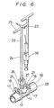
- the threaded portion 27 of the tool shown in Figure 9 is screwed into the connection port 13 of the main body 11 to engage the clamping device using the end of said tool which is lowered into the vertical hole as shown in Figure 5.
- the arms 17 are free.
- the clamping device is lowered and placed on to the gas main pipe 28 when the arms 17 are open using the handle 23 and by manipulating with the tool 22 when connected with the port 13 of the main body.
- a wrench is lowered from ground level to tighten the bolts 21.
- the shoulder portions 17' of arms 17 are pushed down by the parts 19 of arm retainers 18.
- the arms 17 rotate about shafts 16 to embrace the sides of pipe 28 and hold same.
- the clamping device is thus secured to the main pipe 28.
- the tool is removed from the connection port 13 of the clamping device and lifted out to ground level.
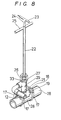
- the threaded portion 27 is then screwed into the upper port 32 of branched coupling 29 as shown in Figure 10 to hold the branched coupling 29, this is then lowered into the vertical hole as illustrated in Figure 7, and secured using handle 23 as shown in Figure 8.
- the cap nut 26 is fitted to the hexagonal section 33 of branched coupling 29 by rotating handle 25 to screw the threaded portion 30 of branched coupling 29 into the thread 14 provided inside the connection port 13 of main body 11 to install the branched coupling 29 on to the clamping device as illustrated in Figure 8.
- the branched pipe is connected to the port on the elbow piece which has previously been connected with the branched coupling 29.
- the tool is detached from the branched coupling and then drilling apparatus 36 is lowered and installed on the upper port 32 of branched coupling 29.
- the gas main pipe 28 is then drilled and the drilling machine detached from the branched coupling and plug 34 is screwed into the upper port 32 of branched coupling 28 to close it.
- the excavation is then back-filled to end. the work.
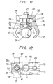
- Figure 11 to Figure 17 shows a practical example. If the arms 17 are loose, they will not open and the clamping device cannot be placed about the gas main pipe 28 when the device is lowered, and this example incorporates a means to overcome this problem.
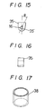
- This means comprises elastic member 35 of A-shape made of rubber, as shown in Figure 15, fitted to the support sections 15 of main body 11 and provided with triangular holes 35.
- the rotary shafts 16 of arms 17 are of a triangular shape to be received within the holes 35' of elastic members 35 so as to open the arms 17, when unloaded and as illustrated in Figure 11.
- the arms 17 have an angle of "theta" with respect to the rotary shafts 16 at all times.
- the coupling between the rotary shafts 16 and elastic members 35 can be of square shape as well as the triangular shape section shown in the example.
- the clamping device can be fastened to the gas main pipe by using a tool from ground level and also all operations in connecting the coupling to the clamping device and also the drilling operation using a hole saw as example can be done from the ground level. There is thus no need for excavating a large vertical shaft to accommodate a worker.
- the vertical shaft to be excavated can be small which shortens the time for excavation and the repair left is smaller.
- the branched pipe connection can be made at almost any location.
- This invention also contemplate the provision of a method for effecting the connection of a ranch pipe to a main pipe.
Landscapes
- Engineering & Computer Science (AREA)
- General Engineering & Computer Science (AREA)
- Mechanical Engineering (AREA)
- Branch Pipes, Bends, And The Like (AREA)
- Drilling And Boring (AREA)
- Supports For Pipes And Cables (AREA)
- Sewage (AREA)
Abstract
Description
- This invention relates to a clamping device for use in connecting a branch pipe to a main pipe which may be buried underground and used for conveying gas or water.
- In connecting a branch pipe to a main pipe a branch coupling is fitted to a connection section of the main pipe. Usually such a connection method for a cast iron gas main uses a threaded hole and the branch coupling is screwed directly into the hole to make the connection.
- However, if the main pipe is made of steel, then it is thinner and hence to join the branched coupling directly to it, as in the case of the cast pipe, is a problem due to the reduced strength. For this reason, a clamping device of the construction as shown in Figure 1 is used. This clamping device has two split structures comprising an
upper shell 2 with a sealing member and a lower shell 3 secured by bolts 4 andnuts 5. The connection of the branched pipe using this clamping device is effected by sinking ashaft 10 into the ground to expose the gasmain pipe 6 as illustrated in Figure 2. An operator then enters thevertical hole 10, places theupper shell 2 on the gasmain pipe 6, applies the lower shell 3 to the lower face, secures both the components with bolts 4 andnuts 5, connects thebranch coupling 9 to theconnection port 7 and then further connects thebranch pipe 8 to thebranch coupling 9. - In the connection of a branch pipe using the conventional clamping device as seen from the aforesaid example, one person at least must enter into the shaft to perform the work. Disadvantages are as follows:-
- a) The shaft must be excavated.
- b) The shaft must be infilled and, in the case of a paved street, a large repair remains evident on the surface.
- c) If space is not available to sink a shaft large enough to accommodate a person then a branch pipe must be extended to a location where the said space is available.
- An object of this invention is to provide a clamping device wherein all operations can be carried out from ground level, without entering the shaft in order to secure the clamp.
- According to this invention there is provided an apparatus as disclosed in
claim 1. - In use the clamping device is fitted to the end of a rod-shaped tool with the arms in a slackened state and then lowered into the vertical shaft. The arms of the clamping device embrace the main pipe. When the clamping device has been set on the main pipe a wrench is lowered, for instance, to clamp and tighten the bolts. In this way, the ends of the arms are pushed to embrace the pipe. By this holding action, the arms can grip the main pipe to secure the clamping device to the main pipe. When secured, the wrench is detached and a branched coupling is lowered onto the connection port of the main body from ground level using the same tool to connect the branched coupling to the connection port of the clamping device. When the connection of the branched coupling has been effected, in order to connect the branched pipe to this branched coupling, a drilling apparatus is lowered to the branched coupling, and a hole cutting saw is lowered onto the main pipe. Through the branched coupling a drilling operation is performed to drill a hole in the main pipe. Once the hole has been drilled in the main pipe, the fluid inside the main pipe enters the branched coupling through the hole and flows toward the branched pipe. The drill is withdrawn after the drilling operation and a plug screwed into the top aperture of the branched coupling to close-off same.
- After connecting the branched pipe as mentioned above, the excavation is back-filled to end the repair work.
- This invention also provides a method of fitting a branch pipe to a main pipe as disclosed in
claim 8. - The invention is further described and illustrated with reference to the accompanying drawings showing an embodiment and also describing the method of operation; in the drawings:-
- Figure 1 shows a part sectional view of a known clamping device,
- Figure 2 shows the method of connection using the known clamping device,
- Figure 3 shows a perspective view of a clamping device of this invention,
- Figure 4 shows a side view of a clamping device as shown in Figure 3,
- Figures 5 to 8 show views of the working method for connecting the clamping device of this invention,
- Figure 9 shows a side view of a tool for lowering the clamping device into the shaft,
- Figure 10 shows a side view of a branched coupling,
- Figure 11 shows a part section of a clamping device with the arms open,
- Figure 12 shows a plan view of a clamping device as shown in Figure 11,
- Figure 13 shows a sectional view with the arms embracing and secured to a gas main,
- Figure 14 shows a side view of the clamping device of Figure 13,
- Figure 15 shows a front view of an elastic resilient member,
- Figure 16 shows a side view of the elastic member, and
- Figure 17 shows a perspective view of a further elastic resilient member.
- The clamping device which enables this invention to be put into practice is shown in Figure 3 and Figure 4.
- In these figures 11 is the clamping device main body, 12 a curved surface formed on the lower side of clamping device
main body 11 for embracing the main pipe, 13 the connection port for the branched coupling and provided in the centre ofmain body 11 withscrew thread 14 inside theconnection port 13. Around the circumference ofconnection port 13 on thecurved face 12 is an O-ring of sealing material which is fitted to improve the sealing property against themain pipe 28. - The upper surface of
main body 11 has protrudingsupport sections 15 formed on both sides of theconnection port 13.Rotary pivot shafts 16 are located on the aforesaid support sections and the shafts are integral with right and left arc- shapedarms 17. Thearms 17 can be rotated freely about therotary shafts 16 which form pivot centres. -
Arm retainers 18 haveabutments 19 engaging the shoulder sections 17' ofarms 17 and are supported bybolts 21 screwed into the thread holes 20 provided between the right and leftarms 17 forming a pair. - Figures 5 to 8 show the means for fitting the clamping device to the gas main pipe.
- Firstly, the threaded
portion 27 of the tool shown in Figure 9 is screwed into theconnection port 13 of themain body 11 to engage the clamping device using the end of said tool which is lowered into the vertical hole as shown in Figure 5. At this time thearms 17 are free. The clamping device is lowered and placed on to the gasmain pipe 28 when thearms 17 are open using thehandle 23 and by manipulating with thetool 22 when connected with theport 13 of the main body. A wrench is lowered from ground level to tighten thebolts 21. When thebolts 21 are tightened in this way, the shoulder portions 17' ofarms 17 are pushed down by theparts 19 ofarm retainers 18. As a result, thearms 17 rotate aboutshafts 16 to embrace the sides ofpipe 28 and hold same. The clamping device is thus secured to themain pipe 28. When the clamping device is secured to the main pipe, the tool is removed from theconnection port 13 of the clamping device and lifted out to ground level. The threadedportion 27 is then screwed into theupper port 32 ofbranched coupling 29 as shown in Figure 10 to hold the branchedcoupling 29, this is then lowered into the vertical hole as illustrated in Figure 7, and secured usinghandle 23 as shown in Figure 8. Thecap nut 26 is fitted to thehexagonal section 33 ofbranched coupling 29 by rotatinghandle 25 to screw the threadedportion 30 ofbranched coupling 29 into thethread 14 provided inside theconnection port 13 ofmain body 11 to install the branchedcoupling 29 on to the clamping device as illustrated in Figure 8. When the aforesaid installation is complete the branched pipe is connected to the port on the elbow piece which has previously been connected with the branchedcoupling 29. The tool is detached from the branched coupling and then drillingapparatus 36 is lowered and installed on theupper port 32 ofbranched coupling 29. The gasmain pipe 28 is then drilled and the drilling machine detached from the branched coupling and plug 34 is screwed into theupper port 32 ofbranched coupling 28 to close it. The excavation is then back-filled to end. the work. - Figure 11 to Figure 17 shows a practical example. If the
arms 17 are loose, they will not open and the clamping device cannot be placed about the gasmain pipe 28 when the device is lowered, and this example incorporates a means to overcome this problem. - This means comprises
elastic member 35 of A-shape made of rubber, as shown in Figure 15, fitted to thesupport sections 15 ofmain body 11 and provided withtriangular holes 35. Therotary shafts 16 ofarms 17 are of a triangular shape to be received within the holes 35' ofelastic members 35 so as to open thearms 17, when unloaded and as illustrated in Figure 11. Thearms 17 have an angle of "theta" with respect to therotary shafts 16 at all times. As a result, since thearms 17 of the clamping device are in an open state when lowered into the vertical shaft from the ground they can be placed around the gasmain pipe 28. - Further, as the
arm retainers 18 are loosely connected with thebolts 21, their weight rests on the shoulders 17' ofarms 17. Theelastic members 35 which receiverotary shafts 16 ofarms 17 are inserted and fitted from above into thesupport sections 15 and there is a possibility of thearms 17 moving upward away from thebody 11, to overcome this the arms are retained using theelastic member 38 which is shown in Figure 17. - In addition, the coupling between the
rotary shafts 16 andelastic members 35 can be of square shape as well as the triangular shape section shown in the example. - As mentioned above, the clamping device can be fastened to the gas main pipe by using a tool from ground level and also all operations in connecting the coupling to the clamping device and also the drilling operation using a hole saw as example can be done from the ground level. There is thus no need for excavating a large vertical shaft to accommodate a worker.
- Consequently, the vertical shaft to be excavated can be small which shortens the time for excavation and the repair left is smaller. The branched pipe connection can be made at almost any location.
- This invention also contemplate the provision of a method for effecting the connection of a ranch pipe to a main pipe.
Claims (8)
Priority Applications (4)
| Application Number | Priority Date | Filing Date | Title |
|---|---|---|---|
| DE8585304504T DE3570731D1 (en) | 1985-06-25 | 1985-06-25 | Branch pipe fittings |
| EP19850304504 EP0205696B1 (en) | 1985-06-25 | 1985-06-25 | Branch pipe fittings |
| AT85304504T ATE43694T1 (en) | 1985-06-25 | 1985-06-25 | ATTACHMENT FOR A BRANCH PIPE. |
| US06/749,104 US4647073A (en) | 1985-06-25 | 1985-06-26 | Clamping device for underground pipes |
Applications Claiming Priority (1)
| Application Number | Priority Date | Filing Date | Title |
|---|---|---|---|
| EP19850304504 EP0205696B1 (en) | 1985-06-25 | 1985-06-25 | Branch pipe fittings |
Publications (2)
| Publication Number | Publication Date |
|---|---|
| EP0205696A1 EP0205696A1 (en) | 1986-12-30 |
| EP0205696B1 true EP0205696B1 (en) | 1989-05-31 |
Family
ID=8194271
Family Applications (1)
| Application Number | Title | Priority Date | Filing Date |
|---|---|---|---|
| EP19850304504 Expired EP0205696B1 (en) | 1985-06-25 | 1985-06-25 | Branch pipe fittings |
Country Status (4)
| Country | Link |
|---|---|
| US (1) | US4647073A (en) |
| EP (1) | EP0205696B1 (en) |
| AT (1) | ATE43694T1 (en) |
| DE (1) | DE3570731D1 (en) |
Families Citing this family (24)
| Publication number | Priority date | Publication date | Assignee | Title |
|---|---|---|---|---|
| GB2185916B (en) * | 1986-01-30 | 1990-10-10 | Water Res Centre | Method of tapping subterranean pipes |
| FR2613811B1 (en) * | 1987-04-07 | 1989-09-29 | Barth Emile | DEVICE FOR CLOGGING REMOTE AND OUT-OF-EXCAVATION GAS LEAKS |
| FR2648538B1 (en) * | 1989-06-19 | 1991-09-13 | Gaz De France | METHOD AND APPARATUS FOR POSITIONING WORKPIECES ON PIPES |
| US5113900A (en) * | 1991-01-30 | 1992-05-19 | Bridge Products, Inc. | Check valve with quick lock attachment feature |
| FR2714710B1 (en) * | 1993-12-30 | 1996-03-15 | Gaz De France | Apparatus for setting up a connection socket on a pipe. |
| US5472011A (en) * | 1994-08-05 | 1995-12-05 | St. Marie; Mark D. | No shut-off repair apparatus for stop valves |
| FR2738614B1 (en) * | 1995-09-12 | 1997-10-17 | Gaz De France | METHOD FOR CONNECTING A BYPASS TO A MAIN PIPING |
| FR2753254B1 (en) * | 1996-09-09 | 1998-10-16 | Gaz De France | CONDUIT CONNECTION METHOD |
| FR2768213B1 (en) * | 1997-09-10 | 1999-11-26 | Gaz De France | METHOD AND DEVICE FOR PLACING A CONNECTION SOCKET FROM THE TOP OF A SEARCH WELL |
| CN1103892C (en) * | 1997-11-06 | 2003-03-26 | 法国天然气国家服务公司 | Method of connecting conduits |
| FR2779206B1 (en) * | 1998-05-27 | 2000-07-28 | Gaz De France | DEVICE FOR MAINTAINING A SECONDARY PIPING ON A CONNECTION SOCKET AND METHOD USING THIS DEVICE TO CONNECT A SECONDARY PIPING TO A MAIN PIPING |
| US6669406B2 (en) * | 2000-05-15 | 2003-12-30 | Omega Tools, Inc. | Method and apparatus for underground connection of pipe |
| CA2313573C (en) | 2000-07-06 | 2004-02-10 | David Albert Nyhuis | Drilling apparatus for tapping into a fluid containing vessel |
| US6516496B2 (en) * | 2001-03-26 | 2003-02-11 | Easy-Con Ltd. | Device for facilitating manual gripping of pipes and connectors |
| FR2869090B1 (en) * | 2004-04-15 | 2007-09-07 | Gaz De France | METHOD FOR CONNECTING A DERIVATION DRIVE TO A MAIN PIPE AND UNDERGROUND FLUID DISTRIBUTION NETWORK |
| FR2869089B1 (en) * | 2004-04-15 | 2006-06-23 | Gaz De France | METHOD AND DEVICE FOR POSTING A CONNECTION TAKEN ON A CANALIZATION |
| US7241084B2 (en) * | 2004-06-30 | 2007-07-10 | Omega Tools, Inc. | Tool assembly with universal coupling for various tools, for work on underground pipes |
| US20060000320A1 (en) * | 2004-06-30 | 2006-01-05 | Hutton William M | Ratchet wrench tool assembly for underground work and process of using |
| US7018137B2 (en) * | 2004-06-30 | 2006-03-28 | Omega Tools, Inc. | Apparatus and process for installing “T” couplings on underground pipe |
| US7699564B2 (en) * | 2007-05-02 | 2010-04-20 | Tdw Delaware, Inc. | Self-contained keyhold weld fitting and method of use |
| US8915675B1 (en) * | 2009-11-23 | 2014-12-23 | Longshot Integrity Services, LLC | Access and connection for a buried pipeline |
| CN103182411B (en) * | 2011-12-29 | 2015-05-27 | 安东石油技术(集团)有限公司 | Net reel and manufacture method thereof |
| GB2517198A (en) * | 2013-08-15 | 2015-02-18 | Jcco 331 Ltd | Improvements in and relating to pipe junctions |
| NO342671B1 (en) | 2017-05-30 | 2018-06-25 | Talgoe Teknologi As | Apparatus for hole punching in an elongated body and method of using the apparatus |
Family Cites Families (11)
| Publication number | Priority date | Publication date | Assignee | Title |
|---|---|---|---|---|
| US204730A (en) * | 1878-06-11 | Improvement in devices for tapping water-pipes | ||
| DE305067C (en) * | ||||
| US691246A (en) * | 1901-03-28 | 1902-01-14 | William D Cram | Pipe connection. |
| US1326392A (en) * | 1919-05-03 | 1919-12-30 | Presley S Combs Jr | Pipe connection. |
| US2230046A (en) * | 1938-06-24 | 1941-01-28 | Sullivan Machinery Co | Drill steel retainer |
| US2736335A (en) * | 1953-03-23 | 1956-02-28 | Claude H Webber | Tapping and cutoff connection to plastic fluid pressure main |
| US3293952A (en) * | 1963-07-30 | 1966-12-27 | Philip R Fairbanks | Pipe hole cutter and method |
| US3815624A (en) * | 1971-04-26 | 1974-06-11 | J Mullins | Copper tube service valve |
| US3847501A (en) * | 1973-05-29 | 1974-11-12 | J Doty | Drill and tap attachment for pipe clamps |
| FR2231915A1 (en) * | 1973-06-04 | 1974-12-27 | Fournier Henri | Temporary coupling for pipe and machine - has shoes on levers controlled by double threaded bolt carrying shoe |
| US4168089A (en) * | 1977-11-02 | 1979-09-18 | Dresser Industries, Inc. | Service connector for plastic gas main |
-
1985
- 1985-06-25 AT AT85304504T patent/ATE43694T1/en active
- 1985-06-25 DE DE8585304504T patent/DE3570731D1/en not_active Expired
- 1985-06-25 EP EP19850304504 patent/EP0205696B1/en not_active Expired
- 1985-06-26 US US06/749,104 patent/US4647073A/en not_active Expired - Fee Related
Also Published As
| Publication number | Publication date |
|---|---|
| US4647073A (en) | 1987-03-03 |
| DE3570731D1 (en) | 1989-07-06 |
| EP0205696A1 (en) | 1986-12-30 |
| ATE43694T1 (en) | 1989-06-15 |
Similar Documents
| Publication | Publication Date | Title |
|---|---|---|
| EP0205696A1 (en) | Branch pipe fittings | |
| CA2053747C (en) | Self-closing clamping apparatus | |
| US4832069A (en) | Tapping subterranean pipes | |
| US7661338B2 (en) | Socket assembly for a gate valve wrench | |
| ES2088153T3 (en) | A DEVICE FOR QUICK CONNECTION OF HYDRAULIC PIPES. | |
| US9028173B2 (en) | Sub-sea apparatus and operating method | |
| CN106164383A (en) | Lock uint for earth mover abrasive element | |
| US5794644A (en) | Adaptor tools and method to expose valve | |
| US4546679A (en) | Riser tee wrench | |
| JP3041346B2 (en) | PVC pipe joint holder for drilling | |
| US5746416A (en) | Adaptor tools and method to expose valve | |
| US11085251B2 (en) | Casing guide and clamp assembly | |
| US5950654A (en) | Adaptor tools and method to expose valve | |
| US20060002765A1 (en) | Tool assembly with universal coupling for various tools, for work on underground pipes | |
| US4610439A (en) | Service saddle U-bolt installation holder | |
| US4836595A (en) | Pipe handling apparatus | |
| CN207155698U (en) | Machine oil filter core dismounts special purpose device | |
| JPH0140398Y2 (en) | ||
| US5819385A (en) | Coupler for use with a buried valve | |
| US6224116B1 (en) | Device for holding pipe on a branch connector | |
| JPH0710456A (en) | Method of suspending a plurality of pipe members, and clampers used therefor | |
| KR200375104Y1 (en) | Pipe joint | |
| US5358002A (en) | Sewer chimney system | |
| JPH04357390A (en) | Push ring pushing device for pipe fittings | |
| KR102558489B1 (en) | resilient seated gate valve for installation zig and it using resilient seated gate valve installation method |
Legal Events
| Date | Code | Title | Description |
|---|---|---|---|
| PUAI | Public reference made under article 153(3) epc to a published international application that has entered the european phase |
Free format text: ORIGINAL CODE: 0009012 |
|
| AK | Designated contracting states |
Kind code of ref document: A1 Designated state(s): AT BE CH DE FR GB IT LI LU NL SE |
|
| 17P | Request for examination filed |
Effective date: 19870126 |
|
| 17Q | First examination report despatched |
Effective date: 19880310 |
|
| GRAA | (expected) grant |
Free format text: ORIGINAL CODE: 0009210 |
|
| AK | Designated contracting states |
Kind code of ref document: B1 Designated state(s): AT BE CH DE FR GB IT LI LU NL SE |
|
| PG25 | Lapsed in a contracting state [announced via postgrant information from national office to epo] |
Ref country code: SE Effective date: 19890531 Ref country code: NL Effective date: 19890531 Ref country code: LI Effective date: 19890531 Ref country code: IT Free format text: LAPSE BECAUSE OF FAILURE TO SUBMIT A TRANSLATION OF THE DESCRIPTION OR TO PAY THE FEE WITHIN THE PRESCRIBED TIME-LIMIT;WARNING: LAPSES OF ITALIAN PATENTS WITH EFFECTIVE DATE BEFORE 2007 MAY HAVE OCCURRED AT ANY TIME BEFORE 2007. THE CORRECT EFFECTIVE DATE MAY BE DIFFERENT FROM THE ONE RECORDED. Effective date: 19890531 Ref country code: CH Effective date: 19890531 Ref country code: BE Effective date: 19890531 Ref country code: AT Effective date: 19890531 |
|
| REF | Corresponds to: |
Ref document number: 43694 Country of ref document: AT Date of ref document: 19890615 Kind code of ref document: T |
|
| REF | Corresponds to: |
Ref document number: 3570731 Country of ref document: DE Date of ref document: 19890706 |
|
| ET | Fr: translation filed | ||
| REG | Reference to a national code |
Ref country code: CH Ref legal event code: PL |
|
| NLV1 | Nl: lapsed or annulled due to failure to fulfill the requirements of art. 29p and 29m of the patents act | ||
| PLBE | No opposition filed within time limit |
Free format text: ORIGINAL CODE: 0009261 |
|
| STAA | Information on the status of an ep patent application or granted ep patent |
Free format text: STATUS: NO OPPOSITION FILED WITHIN TIME LIMIT |
|
| 26N | No opposition filed | ||
| PGFP | Annual fee paid to national office [announced via postgrant information from national office to epo] |
Ref country code: GB Payment date: 19920616 Year of fee payment: 8 |
|
| PGFP | Annual fee paid to national office [announced via postgrant information from national office to epo] |
Ref country code: FR Payment date: 19920629 Year of fee payment: 8 |
|
| PGFP | Annual fee paid to national office [announced via postgrant information from national office to epo] |
Ref country code: DE Payment date: 19920702 Year of fee payment: 8 |
|
| PG25 | Lapsed in a contracting state [announced via postgrant information from national office to epo] |
Ref country code: GB Effective date: 19930625 |
|
| GBPC | Gb: european patent ceased through non-payment of renewal fee |
Effective date: 19930625 |
|
| PG25 | Lapsed in a contracting state [announced via postgrant information from national office to epo] |
Ref country code: FR Effective date: 19940228 |
|
| PG25 | Lapsed in a contracting state [announced via postgrant information from national office to epo] |
Ref country code: DE Effective date: 19940301 |
|
| REG | Reference to a national code |
Ref country code: FR Ref legal event code: ST |
|
| PGFP | Annual fee paid to national office [announced via postgrant information from national office to epo] |
Ref country code: LU Payment date: 19950901 Year of fee payment: 11 |
|
| PG25 | Lapsed in a contracting state [announced via postgrant information from national office to epo] |
Ref country code: LU Free format text: LAPSE BECAUSE OF NON-PAYMENT OF DUE FEES Effective date: 19960625 |