EP0205283B1 - Duct for hot air - Google Patents
Duct for hot air Download PDFInfo
- Publication number
- EP0205283B1 EP0205283B1 EP86304086A EP86304086A EP0205283B1 EP 0205283 B1 EP0205283 B1 EP 0205283B1 EP 86304086 A EP86304086 A EP 86304086A EP 86304086 A EP86304086 A EP 86304086A EP 0205283 B1 EP0205283 B1 EP 0205283B1
- Authority
- EP
- European Patent Office
- Prior art keywords
- duct
- compartment
- exhaust
- hot air
- air
- Prior art date
- Legal status (The legal status is an assumption and is not a legal conclusion. Google has not performed a legal analysis and makes no representation as to the accuracy of the status listed.)
- Expired
Links
Images
Classifications
-
- B—PERFORMING OPERATIONS; TRANSPORTING
- B64—AIRCRAFT; AVIATION; COSMONAUTICS
- B64D—EQUIPMENT FOR FITTING IN OR TO AIRCRAFT; FLIGHT SUITS; PARACHUTES; ARRANGEMENT OR MOUNTING OF POWER PLANTS OR PROPULSION TRANSMISSIONS IN AIRCRAFT
- B64D15/00—De-icing or preventing icing on exterior surfaces of aircraft
- B64D15/02—De-icing or preventing icing on exterior surfaces of aircraft by ducted hot gas or liquid
- B64D15/04—Hot gas application
-
- F—MECHANICAL ENGINEERING; LIGHTING; HEATING; WEAPONS; BLASTING
- F02—COMBUSTION ENGINES; HOT-GAS OR COMBUSTION-PRODUCT ENGINE PLANTS
- F02C—GAS-TURBINE PLANTS; AIR INTAKES FOR JET-PROPULSION PLANTS; CONTROLLING FUEL SUPPLY IN AIR-BREATHING JET-PROPULSION PLANTS
- F02C7/00—Features, components parts, details or accessories, not provided for in, or of interest apart form groups F02C1/00 - F02C6/00; Air intakes for jet-propulsion plants
- F02C7/04—Air intakes for gas-turbine plants or jet-propulsion plants
- F02C7/047—Heating to prevent icing
-
- B—PERFORMING OPERATIONS; TRANSPORTING
- B64—AIRCRAFT; AVIATION; COSMONAUTICS
- B64D—EQUIPMENT FOR FITTING IN OR TO AIRCRAFT; FLIGHT SUITS; PARACHUTES; ARRANGEMENT OR MOUNTING OF POWER PLANTS OR PROPULSION TRANSMISSIONS IN AIRCRAFT
- B64D33/00—Arrangement in aircraft of power plant parts or auxiliaries not otherwise provided for
- B64D33/02—Arrangement in aircraft of power plant parts or auxiliaries not otherwise provided for of combustion air intakes
- B64D2033/0233—Arrangement in aircraft of power plant parts or auxiliaries not otherwise provided for of combustion air intakes comprising de-icing means
Definitions
- This invention relates to a duct for conveying hot air to a selected area on the inside surface of the skin of an aerostructural leading-edge compartment of an aircraft for preventing accumulation of ice on the external leading-edge surface of the said selected area.
- United States Patent Specification No. 2 473 387 corresponding to the features of the preamble of claim 1 discloses a system for directing hot air to the inner surface of the leading edge of an aircraft wing 11.
- a portion of the exhaust gases from an aircraft engine 14 passes through a heat-exchanger 17 to an exhaust pipe 19. Atmospheric air enters a conduit 21 and passes through the heat exchanger 17 where it absorbs heat from the engine exhaust gases, and then passes through a conduit 23 to the entrance path 12 of the aircraft wing 11. After circulating through the wing 11 the exhaust air passes along the path 13 through a conduit 24 and into a chamber 16 of the aircraft. Nose wall sections 38 and 39 are spaced inwardly from the wall 25 of the wing 11 to define passages for the hot air from the entrance path 12.
- An air duct 46 extends along the interior forward portion of the wing 11 and communicates with the inner surface of the wing leading edge through a series of openings 53 in a locking strip 52.
- hot air from the path 12 passes into the air duct 46, through the openings 53 and into the passage defined by the inner wall sections 38 and 39 and the wall 25 of the wing 11. This hot air passes along these passages to warm the wall 25 of the wing forward section, and this air is then returned to the exhaust path 13 through holes 34 in a wing rib section between beams 27 and 28.
- a duct for conveying hot air to a selected area on the inside surface of the skin of an aerostructural leading-edge compartment of an aircraft for preventing accumulation of ice on the external leading edge surface of the said selected area comprising a delivery duct through which hot air is channelled forwardly towards the leading edge, an exhaust duct through which spent air, that is, air which has flowed over the inside skin surface, is channelled rearwardly of the compartment, from the compartment to an exhaust aperture in the aircraft skin, and a heat shield on the area of the skin immediately downstream of the aperture characterised in that the delivery duct is contained within the exhaust duct such that hot air channelled towards the leading edge will be contained by the exhaust duct in the event of rupture of the delivery duct.
- annulus over-pressure indicator is provided so that a failure of the inner duct wall which allows air to pass directly to the exhaust annulus can be detected and subsequent remedial action undertaken.
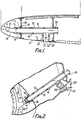
- FIG. 1 there is shown a leading edge compartment 10 of the inlet cowl 11, served by a hot air delivery duct 12 to an air-dispensing spray ring 13, which ring is sealed to the duct 12 by a piston-type seal 14.
- Surrounding the delivery duct 12 is an exhaust duct 15 to define an annular exhaust passage 16 open at its front end 17 to the compartment 10 and sealed to a bulkhead 18 at the rear of the compartment 10 with another piston-type seal 19.
- Exhaust air is channelled along the passage 16 to an outlet duct 20 sealed to the outer duct 15 and to the periphery of an aperture 21 in the skin of the cowl 11, the aperture 21 being covered by a grille 22. Downstream of the aperture 21 is a heat shield 23.
- Within the exhaust passage 16 is a pressure sensor 24, connected to a sensor device arranged to alert cabin staff to any rise in pressure in the passage 16 consistent with rupture of the wall of the delivery duct 12.
- Figure 2 shows, inter alia, more detail of the aperture 21, grille 22 and heat shield 23.
Landscapes
- Engineering & Computer Science (AREA)
- Chemical & Material Sciences (AREA)
- Combustion & Propulsion (AREA)
- Aviation & Aerospace Engineering (AREA)
- Mechanical Engineering (AREA)
- General Engineering & Computer Science (AREA)
- Exhaust Silencers (AREA)
- Duct Arrangements (AREA)
- Joints Allowing Movement (AREA)
- Supports For Pipes And Cables (AREA)
- Structures Of Non-Positive Displacement Pumps (AREA)
Description
- This invention relates to a duct for conveying hot air to a selected area on the inside surface of the skin of an aerostructural leading-edge compartment of an aircraft for preventing accumulation of ice on the external leading-edge surface of the said selected area.
- It is known to channel hot air derived from a turbo fan engine served by an inlet cowl to a spray ring located within an annular leading edge compartment of the cowl. The hot air is sprayed from the spray ring onto the selected skin area and thence exhausts into the engine intake duct by means of an annular slot in the skin at the rear edge of the compartment.
- It will be appreciated that total control over the rate of supply of the hot air may not be practicable, so that there may be occasions when the air exhausting from the exhaust slot into the engine intake is still at a temperature sufficient to introduce a risk of degradation of any composite structures present in the skin immediately downstream of the exhaust slot.
- United States Patent Specification No. 2 473 387 corresponding to the features of the preamble of claim 1 discloses a system for directing hot air to the inner surface of the leading edge of an aircraft wing 11.
- A portion of the exhaust gases from an
aircraft engine 14 passes through a heat-exchanger 17 to anexhaust pipe 19. Atmospheric air enters aconduit 21 and passes through theheat exchanger 17 where it absorbs heat from the engine exhaust gases, and then passes through aconduit 23 to theentrance path 12 of the aircraft wing 11. After circulating through the wing 11 the exhaust air passes along thepath 13 through aconduit 24 and into achamber 16 of the aircraft. Nose wall sections 38 and 39 are spaced inwardly from the wall 25 of the wing 11 to define passages for the hot air from theentrance path 12. - An air duct 46 extends along the interior forward portion of the wing 11 and communicates with the inner surface of the wing leading edge through a series of openings 53 in a locking strip 52.
- In operation, hot air from the
path 12 passes into the air duct 46, through the openings 53 and into the passage defined by the inner wall sections 38 and 39 and the wall 25 of the wing 11. This hot air passes along these passages to warm the wall 25 of the wing forward section, and this air is then returned to theexhaust path 13 through holes 34 in a wing rib section between beams 27 and 28. - With US-A 2 473 387, in the event of rupture of the delivery duct there is the risk that hot air escaping from the delivery duct will contact and degrade parts of the aircraft structure.
- It is an aim of the invention to alleviate the above- mentioned hazards, and according to the present invention there is provided a duct for conveying hot air to a selected area on the inside surface of the skin of an aerostructural leading-edge compartment of an aircraft for preventing accumulation of ice on the external leading edge surface of the said selected area, the duct comprising a delivery duct through which hot air is channelled forwardly towards the leading edge, an exhaust duct through which spent air, that is, air which has flowed over the inside skin surface, is channelled rearwardly of the compartment, from the compartment to an exhaust aperture in the aircraft skin, and a heat shield on the area of the skin immediately downstream of the aperture characterised in that the delivery duct is contained within the exhaust duct such that hot air channelled towards the leading edge will be contained by the exhaust duct in the event of rupture of the delivery duct.
- In a preferred embodiment, there is an open annulus between the inner and outer duct walls at their forward ends thus allowing the spent anti-icing air to pass directly from the leading edge compartment to the duct annulus and thence overboard via the aperture in the outer skin.
- Preferably an annulus over-pressure indicator is provided so that a failure of the inner duct wall which allows air to pass directly to the exhaust annulus can be detected and subsequent remedial action undertaken.
- In the accompanying drawings, given by way of example:
- Figure 1 is a longitudinal, radial section through the wall of an annular inlet cowl, and through an embodiment of a duct in accordance with the present invention; and
- Figure 2 is a perspective view of the embodiment of Figure 1.
- In Figure 1 there is shown a leading
edge compartment 10 of the inlet cowl 11, served by a hotair delivery duct 12 to an air-dispensingspray ring 13, which ring is sealed to theduct 12 by a piston-type seal 14. Surrounding thedelivery duct 12 is anexhaust duct 15 to define anannular exhaust passage 16 open at itsfront end 17 to thecompartment 10 and sealed to abulkhead 18 at the rear of thecompartment 10 with another piston-type seal 19. Exhaust air is channelled along thepassage 16 to anoutlet duct 20 sealed to theouter duct 15 and to the periphery of anaperture 21 in the skin of the cowl 11, theaperture 21 being covered by agrille 22. Downstream of theaperture 21 is aheat shield 23. Within theexhaust passage 16 is apressure sensor 24, connected to a sensor device arranged to alert cabin staff to any rise in pressure in thepassage 16 consistent with rupture of the wall of thedelivery duct 12. - Figure 2 shows, inter alia, more detail of the
aperture 21,grille 22 andheat shield 23.
Claims (5)
Applications Claiming Priority (2)
| Application Number | Priority Date | Filing Date | Title |
|---|---|---|---|
| GB8513904 | 1985-06-03 | ||
| GB8513904 | 1985-06-03 |
Publications (2)
| Publication Number | Publication Date |
|---|---|
| EP0205283A1 EP0205283A1 (en) | 1986-12-17 |
| EP0205283B1 true EP0205283B1 (en) | 1989-05-24 |
Family
ID=10580064
Family Applications (1)
| Application Number | Title | Priority Date | Filing Date |
|---|---|---|---|
| EP86304086A Expired EP0205283B1 (en) | 1985-06-03 | 1986-05-29 | Duct for hot air |
Country Status (9)
| Country | Link |
|---|---|
| US (1) | US4757963A (en) |
| EP (1) | EP0205283B1 (en) |
| JP (1) | JPS62268800A (en) |
| AU (1) | AU578153B2 (en) |
| BR (1) | BR8602400A (en) |
| CA (1) | CA1270237A (en) |
| DE (1) | DE3663503D1 (en) |
| ES (1) | ES8706546A1 (en) |
| IL (2) | IL78786A0 (en) |
Families Citing this family (45)
| Publication number | Priority date | Publication date | Assignee | Title |
|---|---|---|---|---|
| GB2217393B (en) * | 1988-04-14 | 1992-07-08 | Rolls Royce Plc | Nose bullet anti-icing for gas turbine engines |
| US5011098A (en) * | 1988-12-30 | 1991-04-30 | The Boeing Company | Thermal anti-icing system for aircraft |
| GB9120113D0 (en) * | 1991-09-20 | 1992-09-23 | Short Brothers Plc | Thermal antiicing of aircraft structures |
| US5257498A (en) * | 1992-04-23 | 1993-11-02 | United Technologies Corporation | Efficient anti-ice exhaust vent |
| US6003814A (en) * | 1996-06-17 | 1999-12-21 | Seniors Flexonics Inc. Stainless Steel Products Division | Double-walled duct assembly for aircraft anti-icing conduit systems |
| US5841079A (en) * | 1997-11-03 | 1998-11-24 | Northrop Grumman Corporation | Combined acoustic and anti-ice engine inlet liner |
| FR2771451B1 (en) * | 1997-11-21 | 2000-04-14 | Aerospatiale | PROTECTION DEVICE FOR REACTION ENGINE AIR INTAKE COVER, EQUIPPED WITH DEFROSTING SYSTEM |
| FR2771776B1 (en) * | 1997-12-02 | 2000-01-28 | Aerospatiale | HOT AIR DISCHARGE DEVICE FOR REACTION ENGINE AIR INTAKE COVER WITH DEFROSTING CIRCUIT |
| US6688558B2 (en) | 1999-11-23 | 2004-02-10 | The Boeing Company | Method and apparatus for aircraft inlet ice protection |
| US6371411B1 (en) | 1999-11-23 | 2002-04-16 | The Boeing Company | Method and apparatus for aircraft inlet ice protection |
| FR2802573B1 (en) * | 1999-12-21 | 2002-02-15 | Aerospatiale Matra Airbus | HOT AIR DISCHARGE DEVICE FOR REACTION ENGINE AIR INTAKE COVER WITH DEFROSTING CIRCUIT |
| FR2820716B1 (en) * | 2001-02-15 | 2003-05-30 | Eads Airbus Sa | PROCESS FOR DEFROSTING BY FORCED CIRCULATION OF A FLUID, OF A REACTION ENGINE AIR INLET COVER AND DEVICE FOR ITS IMPLEMENTATION |
| FR2823533B1 (en) | 2001-04-17 | 2003-08-08 | Eads Airbus Sa | AIR INLET HOOD FOR REACTION ENGINE, PROVIDED WITH DEFROSTING MEANS |
| US6910659B2 (en) * | 2002-10-22 | 2005-06-28 | The Boeing Company | Method and apparatus for liquid containment, such as for aircraft fuel vessels |
| US7175136B2 (en) | 2003-04-16 | 2007-02-13 | The Boeing Company | Method and apparatus for detecting conditions conducive to ice formation |
| US7331421B2 (en) * | 2005-03-30 | 2008-02-19 | The Boeing Company | Flow restrictors for aircraft inlet acoustic treatments, and associated systems and methods |
| FR2886674B1 (en) | 2005-06-07 | 2007-08-03 | Airbus France Sas | SYSTEM FOR DEFROSTING THE EDGE OF AN AIR INLET HOOD FOR A TURBOMOTEUR |
| FR2887294B1 (en) * | 2005-06-21 | 2007-08-10 | Airbus France Sas | SYSTEM FOR DEFROSTING THE EDGE OF AN AIR INLET HOOD FOR A TURBOMOTEUR |
| EP1739013B1 (en) * | 2005-07-01 | 2008-05-28 | Saab Ab | A device and an aircraft anti-icing system comprising such a device |
| FR2904604B1 (en) * | 2006-08-04 | 2009-02-27 | Airbus France Sas | STRUCTURE ELEMENT OF AN AIRCRAFT |
| GB2442967B (en) * | 2006-10-21 | 2011-02-16 | Rolls Royce Plc | An engine arrangement |
| US8082726B2 (en) * | 2007-06-26 | 2011-12-27 | United Technologies Corporation | Tangential anti-swirl air supply |
| FR2921901B1 (en) * | 2007-10-08 | 2011-03-18 | Aircelle Sa | AIR INTAKE STRUCTURE CAPABLE OF BEING MOUNTED BEFORE MEDIUM NACELLE STRUCTURE FOR AN AIRCRAFT ENGINE, AND NACELLE EQUIPPED WITH SUCH AN AIR INTAKE STRUCTURE |
| US7900872B2 (en) * | 2007-12-12 | 2011-03-08 | Spirit Aerosystems, Inc. | Nacelle inlet thermal anti-icing spray duct support system |
| GB0812562D0 (en) * | 2008-07-10 | 2008-08-13 | Airbus Uk Ltd | A Connector for an aircraft fuel pipe |
| FR2951436B1 (en) * | 2009-10-15 | 2011-12-09 | Airbus Operations Sas | AIRCRAFT TURBOHOMOTER HANDLING MACHINE WITH CONCENTRIC HOT AIR PIPING |
| FR2954279B1 (en) * | 2009-12-18 | 2014-08-22 | Airbus Operations Sas | AIR INTAKE OF AN AIRCRAFT NACELLE INCORPORATING HOT AIR INJECTION MEANS FOR OPTIMIZED GEL TREATMENT |
| US8382039B2 (en) * | 2009-12-30 | 2013-02-26 | MRA Systems Inc. | Turbomachine nacelle and anti-icing system and method therefor |
| FR2957586B1 (en) * | 2010-03-18 | 2012-04-27 | Airbus Operations Sas | DEFROSTING DEVICE COMPRISING MEANS FOR DETECTING A LEAK AT A HOT AIR SUPPLY |
| US8974177B2 (en) | 2010-09-28 | 2015-03-10 | United Technologies Corporation | Nacelle with porous surfaces |
| GB201116337D0 (en) * | 2011-09-21 | 2011-11-02 | Airbus Operations Ltd | Bleed air duct joint insulation means |
| CN103184935B (en) * | 2011-12-28 | 2015-06-10 | 中航商用航空发动机有限责任公司 | Hot-air anti-icer for engine inlet |
| CN102756809B (en) * | 2012-07-07 | 2014-05-07 | 北京航空航天大学 | Opened type airplane hot-gas anti-icing test device |
| US10734622B2 (en) | 2013-02-25 | 2020-08-04 | The Boeing Company | Ventilation conduit for an aircraft |
| US9663233B2 (en) | 2013-02-25 | 2017-05-30 | The Boeing Company | Ventilation conduit for an aircraft |
| US9528442B2 (en) * | 2013-08-21 | 2016-12-27 | The Boeing Company | Aircraft engine anti-icing (EAI) barrier assembly, system and method |
| US10138811B2 (en) * | 2014-03-13 | 2018-11-27 | The Boeing Company | Enhanced temperature control anti-ice nozzle |
| CN104929778B (en) * | 2014-03-18 | 2017-08-25 | 中国航发商用航空发动机有限责任公司 | Engine inlets anti-icing system |
| FR3021350B1 (en) * | 2014-05-20 | 2016-07-01 | Snecma | METHOD FOR DETECTING FLUID LEAKAGE IN TURBOMACHINE AND FLUID DISPENSING SYSTEM |
| FR3031141B1 (en) * | 2014-12-24 | 2017-02-10 | Snecma | METHOD FOR DETECTING FLUID LEAKAGE IN TURBOMACHINE AND FLUID DISPENSING SYSTEM |
| FR3079590B1 (en) * | 2018-03-29 | 2021-01-29 | Safran Aircraft Engines | CONNECTION DEVICE FOR AN AIR CIRCUIT OF AN AIRCRAFT ENGINE |
| US11002188B2 (en) | 2018-09-14 | 2021-05-11 | Rohr, Inc. | Nozzle for an aircraft propulsion system |
| US11220344B2 (en) * | 2018-12-17 | 2022-01-11 | Rohr, Inc. | Anti-ice double walled duct system |
| EP3878751B1 (en) | 2020-03-13 | 2023-08-30 | Rohr, Inc. | Nozzle for a thermal anti-icing system |
| CN116696550A (en) * | 2023-07-14 | 2023-09-05 | 中国航发沈阳发动机研究所 | Aeroengine air inlet casing fairing |
Family Cites Families (9)
| Publication number | Priority date | Publication date | Assignee | Title |
|---|---|---|---|---|
| US2081963A (en) * | 1935-09-26 | 1937-06-01 | Theodorsen Theodore | Vapor heating system |
| US2207242A (en) * | 1937-06-15 | 1940-07-09 | Seversky Aircraft Corp | Aircraft structure |
| US2473387A (en) * | 1947-05-28 | 1949-06-14 | Curtiss Wright Corp | Anti-icing means for aircraft |
| US2868483A (en) * | 1952-02-08 | 1959-01-13 | Rudolph E Krueger | Anti-icing control system |
| US2820601A (en) * | 1953-03-09 | 1958-01-21 | Northrop Aircraft Inc | Movable wing tip |
| DE2115271A1 (en) * | 1971-03-30 | 1972-10-26 | Wieland-Werke Ag, 7900 Ulm | Heat transfer tube with leak indicator |
| US4482114A (en) * | 1981-01-26 | 1984-11-13 | The Boeing Company | Integrated thermal anti-icing and environmental control system |
| US4406431A (en) * | 1981-11-23 | 1983-09-27 | Omac, Inc. | Air scoop lip warmer de-icing system |
| US4603824A (en) * | 1983-08-12 | 1986-08-05 | The Boeing Company | Wing slat anti-ice air duct system with improved slide bearings and air seal |
-
1985
- 1985-05-15 IL IL78786A patent/IL78786A0/en unknown
-
1986
- 1986-05-09 AU AU57300/86A patent/AU578153B2/en not_active Ceased
- 1986-05-15 IL IL78786A patent/IL78786A/en not_active IP Right Cessation
- 1986-05-16 JP JP61110947A patent/JPS62268800A/en active Pending
- 1986-05-27 BR BR8602400A patent/BR8602400A/en not_active IP Right Cessation
- 1986-05-28 US US06/868,286 patent/US4757963A/en not_active Expired - Lifetime
- 1986-05-29 EP EP86304086A patent/EP0205283B1/en not_active Expired
- 1986-05-29 DE DE8686304086T patent/DE3663503D1/en not_active Expired
- 1986-06-02 CA CA000510595A patent/CA1270237A/en not_active Expired
- 1986-06-02 ES ES555580A patent/ES8706546A1/en not_active Expired
Also Published As
| Publication number | Publication date |
|---|---|
| DE3663503D1 (en) | 1989-06-29 |
| ES555580A0 (en) | 1987-07-01 |
| CA1270237A (en) | 1990-06-12 |
| EP0205283A1 (en) | 1986-12-17 |
| BR8602400A (en) | 1987-01-21 |
| AU5730086A (en) | 1986-12-11 |
| IL78786A0 (en) | 1986-08-31 |
| US4757963A (en) | 1988-07-19 |
| AU578153B2 (en) | 1988-10-13 |
| IL78786A (en) | 1990-11-29 |
| ES8706546A1 (en) | 1987-07-01 |
| JPS62268800A (en) | 1987-11-21 |
Similar Documents
| Publication | Publication Date | Title |
|---|---|---|
| US4757963A (en) | Duct for hot air | |
| US5088277A (en) | Aircraft engine inlet cowl anti-icing system | |
| US5697394A (en) | Low observable engine air inlet system | |
| US5655732A (en) | Apparatus for draining waste water from aircraft | |
| EP0968918B1 (en) | Auxiliary power unit passive cooling system | |
| CA1272177A (en) | Hot air deicing duct rupture indicator | |
| IL103208A (en) | Thermal anti-icing of aircraft structures | |
| US5484122A (en) | Turbine exhaust gas anti-ice system | |
| US11667388B2 (en) | Apparatus and method for heating an aircraft structure | |
| US5884873A (en) | Suction generator system in an aircraft for maintaining a laminar boundary flow | |
| EP0719416A1 (en) | Integral airfoil total temperature sensor | |
| US4976397A (en) | Anti-icing system for aircraft | |
| GB1201096A (en) | Air particle separator | |
| US4741499A (en) | Anti-icing system for aircraft | |
| GB2085082A (en) | Auxiliary air system for gas turbine engine | |
| EP0406155B1 (en) | Infrared suppressor for a gas turbine engine | |
| EP0536089B1 (en) | A system for discharging the heating fluid from an anti-icing device in the air intake of a turbojet engine at a low pressure and with a high degree of mixing | |
| CN105793542A (en) | Aircraft propulsion assembly with fire suppression system | |
| US6241189B1 (en) | Protective device for a jet engine air inlet cowl equipped with a deicing system | |
| US4425756A (en) | Gas turbine engine and its associated air intake system | |
| US3971511A (en) | Cabin heater for helicopters and fixed wing aircraft | |
| GB741336A (en) | Anti-icing means for a gas turbine engine of an aircraft | |
| US4493195A (en) | Air conditioning system with evaporative cooling apparatus | |
| US20240301826A1 (en) | Aircraft turboprop engine inlet compact profile configuration | |
| US6886782B2 (en) | System for supplying an aircraft with cool air |
Legal Events
| Date | Code | Title | Description |
|---|---|---|---|
| PUAI | Public reference made under article 153(3) epc to a published international application that has entered the european phase |
Free format text: ORIGINAL CODE: 0009012 |
|
| AK | Designated contracting states |
Kind code of ref document: A1 Designated state(s): DE FR GB IT NL SE |
|
| 17P | Request for examination filed |
Effective date: 19870326 |
|
| 17Q | First examination report despatched |
Effective date: 19871104 |
|
| ITF | It: translation for a ep patent filed | ||
| GRAA | (expected) grant |
Free format text: ORIGINAL CODE: 0009210 |
|
| AK | Designated contracting states |
Kind code of ref document: B1 Designated state(s): DE FR GB IT NL SE |
|
| REF | Corresponds to: |
Ref document number: 3663503 Country of ref document: DE Date of ref document: 19890629 |
|
| ET | Fr: translation filed | ||
| PLBE | No opposition filed within time limit |
Free format text: ORIGINAL CODE: 0009261 |
|
| STAA | Information on the status of an ep patent application or granted ep patent |
Free format text: STATUS: NO OPPOSITION FILED WITHIN TIME LIMIT |
|
| 26N | No opposition filed | ||
| ITTA | It: last paid annual fee | ||
| EAL | Se: european patent in force in sweden |
Ref document number: 86304086.1 |
|
| PGFP | Annual fee paid to national office [announced via postgrant information from national office to epo] |
Ref country code: SE Payment date: 19950405 Year of fee payment: 10 |
|
| PGFP | Annual fee paid to national office [announced via postgrant information from national office to epo] |
Ref country code: DE Payment date: 19950516 Year of fee payment: 10 |
|
| PGFP | Annual fee paid to national office [announced via postgrant information from national office to epo] |
Ref country code: NL Payment date: 19950531 Year of fee payment: 10 |
|
| PG25 | Lapsed in a contracting state [announced via postgrant information from national office to epo] |
Ref country code: SE Effective date: 19960530 |
|
| PG25 | Lapsed in a contracting state [announced via postgrant information from national office to epo] |
Ref country code: NL Effective date: 19961201 |
|
| PG25 | Lapsed in a contracting state [announced via postgrant information from national office to epo] |
Ref country code: DE Effective date: 19970201 |
|
| EUG | Se: european patent has lapsed |
Ref document number: 86304086.1 |
|
| NLV4 | Nl: lapsed or anulled due to non-payment of the annual fee |
Effective date: 19961201 |
|
| REG | Reference to a national code |
Ref country code: GB Ref legal event code: IF02 |
|
| PGFP | Annual fee paid to national office [announced via postgrant information from national office to epo] |
Ref country code: GB Payment date: 20040326 Year of fee payment: 19 |
|
| PGFP | Annual fee paid to national office [announced via postgrant information from national office to epo] |
Ref country code: FR Payment date: 20040524 Year of fee payment: 19 |
|
| PG25 | Lapsed in a contracting state [announced via postgrant information from national office to epo] |
Ref country code: IT Free format text: LAPSE BECAUSE OF NON-PAYMENT OF DUE FEES;WARNING: LAPSES OF ITALIAN PATENTS WITH EFFECTIVE DATE BEFORE 2007 MAY HAVE OCCURRED AT ANY TIME BEFORE 2007. THE CORRECT EFFECTIVE DATE MAY BE DIFFERENT FROM THE ONE RECORDED. Effective date: 20050529 Ref country code: GB Free format text: LAPSE BECAUSE OF NON-PAYMENT OF DUE FEES Effective date: 20050529 |
|
| GBPC | Gb: european patent ceased through non-payment of renewal fee |
Effective date: 20050529 |
|
| PG25 | Lapsed in a contracting state [announced via postgrant information from national office to epo] |
Ref country code: FR Free format text: LAPSE BECAUSE OF NON-PAYMENT OF DUE FEES Effective date: 20060131 |
|
| REG | Reference to a national code |
Ref country code: FR Ref legal event code: ST Effective date: 20060131 |