EP0205219B1 - A cattle feeding station - Google Patents
A cattle feeding station Download PDFInfo
- Publication number
- EP0205219B1 EP0205219B1 EP86200996A EP86200996A EP0205219B1 EP 0205219 B1 EP0205219 B1 EP 0205219B1 EP 86200996 A EP86200996 A EP 86200996A EP 86200996 A EP86200996 A EP 86200996A EP 0205219 B1 EP0205219 B1 EP 0205219B1
- Authority
- EP
- European Patent Office
- Prior art keywords
- feeding station
- feeding
- trough
- animal
- station according
- Prior art date
- Legal status (The legal status is an assumption and is not a legal conclusion. Google has not performed a legal analysis and makes no representation as to the accuracy of the status listed.)
- Expired - Lifetime
Links
- 241000283690 Bos taurus Species 0.000 title claims abstract description 12
- 241001465754 Metazoa Species 0.000 claims abstract description 67
- 239000007788 liquid Substances 0.000 claims description 5
- 239000003550 marker Substances 0.000 claims description 3
- 239000004020 conductor Substances 0.000 claims 1
- 230000000694 effects Effects 0.000 description 3
- 239000000945 filler Substances 0.000 description 3
- PXHVJJICTQNCMI-UHFFFAOYSA-N Nickel Chemical compound [Ni] PXHVJJICTQNCMI-UHFFFAOYSA-N 0.000 description 2
- 230000004888 barrier function Effects 0.000 description 2
- 238000010276 construction Methods 0.000 description 2
- 239000000975 dye Substances 0.000 description 2
- 244000144980 herd Species 0.000 description 2
- 238000005192 partition Methods 0.000 description 2
- 206010038743 Restlessness Diseases 0.000 description 1
- 238000001514 detection method Methods 0.000 description 1
- 230000035558 fertility Effects 0.000 description 1
- 238000009434 installation Methods 0.000 description 1
- 230000002452 interceptive effect Effects 0.000 description 1
- 230000004048 modification Effects 0.000 description 1
- 238000012986 modification Methods 0.000 description 1
- 229910052759 nickel Inorganic materials 0.000 description 1
- 238000009877 rendering Methods 0.000 description 1
- 239000002689 soil Substances 0.000 description 1
- 239000007787 solid Substances 0.000 description 1
- XLYOFNOQVPJJNP-UHFFFAOYSA-N water Substances O XLYOFNOQVPJJNP-UHFFFAOYSA-N 0.000 description 1
Images

Classifications
-
- A—HUMAN NECESSITIES
- A01—AGRICULTURE; FORESTRY; ANIMAL HUSBANDRY; HUNTING; TRAPPING; FISHING
- A01K—ANIMAL HUSBANDRY; AVICULTURE; APICULTURE; PISCICULTURE; FISHING; REARING OR BREEDING ANIMALS, NOT OTHERWISE PROVIDED FOR; NEW BREEDS OF ANIMALS
- A01K1/00—Housing animals; Equipment therefor
- A01K1/0005—Stable partitions
- A01K1/0017—Gates, doors
- A01K1/0023—Sorting gates
-
- A—HUMAN NECESSITIES
- A01—AGRICULTURE; FORESTRY; ANIMAL HUSBANDRY; HUNTING; TRAPPING; FISHING
- A01K—ANIMAL HUSBANDRY; AVICULTURE; APICULTURE; PISCICULTURE; FISHING; REARING OR BREEDING ANIMALS, NOT OTHERWISE PROVIDED FOR; NEW BREEDS OF ANIMALS
- A01K1/00—Housing animals; Equipment therefor
- A01K1/02—Pigsties; Dog-kennels; Rabbit-hutches or the like
- A01K1/0209—Feeding pens for pigs or cattle
Definitions
- the present invention relates to a cattle feeding station comprising two side walls between which an animal to be fed can be present, at least one end wall at one end of the feeding station, a feeding trough located at the said end, including an identification system for identifying an animal present in the feeding station and further including a computer-controlled fodder dispenser, wherein the end wall is formed at least substantially by the feeding trough.
- the animals are present at the entrance of one or more feeding stations.
- the entrance of a feeding station is located opposite the said end wall and may include a door.
- a feeding station is free, one of the animals to be fed will move into the station.
- the identification system As soon as the animal inserts its head into the feeding trough, it is identified by the identification system. To this end, each animal is wearing a responder mostly hanging from the neck, wherein, under the influence of an electromagnetic interrogation field produced by the said system, there is generated a code signal that is unique for the animal in question and which is detected by the said system.
- the identification system is connected to, or fitted with, a computer which, after identification of the animal present in the feeding station, and on the basis of further data fed into the computer store by the cattle farmer, determines the quantity and, possibly, the type of fodder the animal should receive.
- the computer applies control signals to the fodder dispenser, which subsequently supplies the desired quantity and type of fodder to the feeding trough.
- a drawback of the above described prior art feeding station is that an animal that has finished eating has to leave the feeding station backwards. This backward movement is a drawback of the otherwise simple station.
- the animal On the one hand, the animal is not inclined to leave the station, since more fodder might be supplied, so that it will linger a little while.
- hungry animals will often have gathered at the entrance of the feeding station, which will impede or in any case delay the backward movement of the animal in the feeding box, while, moreover there is a substantial amount of unrest in the cattle house and the animals may even become aggressive. From the viewpoint of efficiency, a maximum number of animals will be fed with one feeding station. Delay in the eating cycle by lingering in the feeding box and slowly moving backwards against the resistance of the animals therebehind should thus be opposed.
- a feeding station of the above described type is characterized in that the feeding trough is movable about a substantially vertical shaft in such a manner that the end wall under control of appropriate operating means, can be brought in a position closing the feeding station, wherein the feeding trough is accessible to an animal present in the feeding station and in at least one other position leaving the end of the feeding station concerned open, wherein the feeding trough is inaccessible to an animal present in the feeding station.
- EP-A-0091892 describes a milking station comprising means for automatically applying a milking cluster to a cow in the milking position.
- This milking station is also provided at one end wall with a manger and with means for automatically identifying a cow present in the milking station and with computer-controlled fodder supplying means.
- the manger is not arranged in a movable end wall, and cannot be moved out of reach of a cow.
- the prior milking station is open at one end only, so that the cows have to enter and leave it through one and the same doorway.
- US-A-4,129,096 discloses a pig feeding station having two sidewalls and a first end wall formed by an access door and a second end wall provided with a manger.
- the known pig feeding station does not comprise means for automatically identifying an animal present in the feeding station, and also is not provided with a computer-controlled fodder supplying apparatus.
- the end wall provided with a manger is formed as an exit door.
- the exit door is not, however, movable relatively to a vertical shaft, but is pivoted about a horizontal shaft which coincides with the upper edge of the door.
- One disadvantage of this construction is that, as the exit door is opened, any fodder residues contained in the manger will drop out of the manger, and soil the feeding station and also the animal leaving it. Moreover, this falling fodder will tend to attract other animals, thereby interfering with a smooth passage of the animals through the feeding station.
- the prior art station shown in Figs. 1 and 2 comprises a stationary feeding trough 1 from which fodder can be eaten, with a superimposed dispenser 2 and a supply container 3.
- the animal e.g. a pig, wearing e.g. a collar with a detection means (a so- called responder) is identified, since this responder, arriving in the vicinity of the electromagnetic interrogation field of detector 4, will transmit a code uniqueforthe animal concerned.
- This code is processed in a computer so that it is decided automatically, in a manner predetermined by the cattle breeder, whether the animal is entitled to any fodder, and if so, how much, after which the dispensing of the fodder can be started.
- such a feeding station is usually fitted with two side walls 5 and 6 and sometimes also with an entrance door 7, which is closed as soon as the animal is present within the feeding box thus produced.
- the entrance door 7 will be opened under computer control, with the animal leaving the feeding station in backward direction.
- Figs. 3 and 4 show a first embodiment of a feeding station according to the present invention.
- the station shown includes again side walls 5,6, a feeding trough 30 disposed at the one end, said trough having again a detector 4 for a responder.
- a door31 which may be constructed as a single door, two half-doors, one hanging door or as a sliding door. In the embodiment shown, use is made of a specially formed door which occupies little space and which will be further described hereinafter.
- the feeding trough 30 in this embodiment has a substantially triangular form the front of which, proximal to the feeding station, as shown, may have a curved shape and has an entrance opening for the head of an animal. At the apex of the triangular feeding trough, distal from the feeding station, it is mounted for pivotal movement about a vertical shaft 8. In the eating position, the feeding trough entirely closes the feeding station and the fodder present in the trough is accessible to an animal present in the feeding station.
- the front of the trough may alternatively have a smaller width than the width of the feeding station, in which case it would be incorporated in an end wall further shutting off the feeding station.
- the trough is also connected to an operating member 9 which, as shown, may be a hydraulic or pneumatic cylinder which, on energization will rotate the trough about the vertical shaft 8 into such a position that an animal present in the feeding station can leave the station in forward direction. Such a position is shown at 10 in broken lines. In this position, the fodder is out of reach of the animal. Preferably, the side walls of the trough are closed, so that any fodder remaining in the trough is no longer visible to the animal, so that it will leave the feeding station rapidly.
- Operating member 9 is energized preferably automatically e.g. under computer control.
- the operating member can be energized a predetermined period of time after an animal present in the feeding station has been identified and the fodder has been supplied to the trough, so as to open the exit of the station.
- the predetermined period of time may depend on the quantity of fodder received by the animal. Subsequently, e.g. after a second predetermined period of time, the trough may be returned to the closing position, while at the same time the entrance of the feeding station is opened.
- the closing of the exit and the opening of the entrance may also be controlled, starting from signals provided by a separate detector arranged adjacent the exit of the station.
- a separate detector arranged adjacent the exit of the station.
- a light barrier or a depression contact may be disposed in the floor in the path of exit of the animal.
- Such a light barrier is indicated diagrammatically at 32 in Fig. 3.
- the fodder supply device 2, 3 can be mounted, at choice, either for it to rotate along with the trough or for it to be in a stationary position. In the latter case, the fodder supply device has such a high position that the trough can rotate freely about the vertical shaft 8.
- exit of the feeding station may alternatively be arranged to be cleared by sliding the trough along the vertical shaft 8 in upward direction.
- the entrance is provided with an access door 31 as shown in Fig. 4.
- Door 31 includes a bent plate attached to arms 11, 12 extending along the side walls 5, 6 and having pivots 13, 14.
- Door 31 can be swung upwards into the position 15 shown in broken lines, e.g. moved by an air cylinder 16.
- one or more depending chains 17 may be fitted on a cross rod 18 to which, after a given delay period, short, harmless voltage pulses are applied as in an electricfence installation. The animal could also be pushed on mechanically to ensure that it leaves the feeding box.
- the feeding station shown may be provided with a marker, e.g. consisting of a dye container 20, electric magnet valve 21 and outlet 22. Valve 21 can be opened through computer control so that the animal then present in the feeding box receives a colour mark, allowing it to be separated subsequently from the herd, e.g. in connection with the state of fertility of the animal.
- a further extension of the feeding station shown may be a liquid dispenser 23, by means of which a liquid (e.g. water) is supplied via a magnet valve 24 to the usually solid fodder. This increases the eating speed considerably, while also feeding trough 1 remains cleaner, thereby preventing fodder rests from getting mouldy.
- Fig. 5 shows an embodiment similar to that of Fig. 3 with the added possibility of separating the animals.
- the feeding trough 30 can now not only be moved into position 10 but also into a second position 25, e.g. by means of the air cylinder 9.
- an animal coming from A via the feeding station can be conducted selectively into space B or C by placing the trough, after eating, in position 25 or in position 10. In this manner e.g. fertile or sick animals can be isolated from the rest of the herd by computer control.
- this station too can be provided with an ousting device 17, 18, marker 20, 21, 22 and liquid dispenser 23, 24 possibly with various dyes indicating the required treatment or care.
- Fig. 5 shows how the depth d of the feeding station can be reduced and thereby adjusted to the length of the animal.
- a filler 29 can be attached against the door 7 in a simple manner, e.g. by means of screwed bolts with wing nuts. This filler extends along at least a part of the height of the door. By using fillers of different depths a (obtained possibly by adjustability) the effective length d of the station can be adjusted as desired.
- width b of the feeding station can be made adjustable, if desired, in an otherwise known manner not further indicated by rendering partitions 5 and/or 6 movable in the width direction b of the station.
- the feeding station described makes it possible to effectively feed animals partly or entirely automatically, with a short eating cycle, so that relatively many animals can be fed with one feeding station.
Landscapes
- Life Sciences & Earth Sciences (AREA)
- Environmental Sciences (AREA)
- Zoology (AREA)
- Animal Husbandry (AREA)
- Biodiversity & Conservation Biology (AREA)
- Feeding And Watering For Cattle Raising And Animal Husbandry (AREA)
Abstract
Description
- The present invention relates to a cattle feeding station comprising two side walls between which an animal to be fed can be present, at least one end wall at one end of the feeding station, a feeding trough located at the said end, including an identification system for identifying an animal present in the feeding station and further including a computer-controlled fodder dispenser, wherein the end wall is formed at least substantially by the feeding trough.
- A similar station is known in practice. The operation of such a known feeding station is as follows.
- During the feeding period of the animals to be fed, the animals are present at the entrance of one or more feeding stations. The entrance of a feeding station is located opposite the said end wall and may include a door. When a feeding station is free, one of the animals to be fed will move into the station. As soon as the animal inserts its head into the feeding trough, it is identified by the identification system. To this end, each animal is wearing a responder mostly hanging from the neck, wherein, under the influence of an electromagnetic interrogation field produced by the said system, there is generated a code signal that is unique for the animal in question and which is detected by the said system.
- An embodiment of such an identification system, and in particular a responder therefor, is described e.g. in US patent 4,196,418.
- The identification system is connected to, or fitted with, a computer which, after identification of the animal present in the feeding station, and on the basis of further data fed into the computer store by the cattle farmer, determines the quantity and, possibly, the type of fodder the animal should receive. The computer, to this effect, applies control signals to the fodder dispenser, which subsequently supplies the desired quantity and type of fodder to the feeding trough.
- In this manner a great many animals can be fed automatically by means of one or more of such feeding stations.
- A drawback of the above described prior art feeding station is that an animal that has finished eating has to leave the feeding station backwards. This backward movement is a drawback of the otherwise simple station. On the one hand, the animal is not inclined to leave the station, since more fodder might be supplied, so that it will linger a little while. Moreover, hungry animals will often have gathered at the entrance of the feeding station, which will impede or in any case delay the backward movement of the animal in the feeding box, while, moreover there is a substantial amount of unrest in the cattle house and the animals may even become aggressive. From the viewpoint of efficiency, a maximum number of animals will be fed with one feeding station. Delay in the eating cycle by lingering in the feeding box and slowly moving backwards against the resistance of the animals therebehind should thus be opposed.
- In the feeding station according to the present invention, both reasons for delaying the departure from the station by the animal have been minimized.
- To this effect, according to the present invention, a feeding station of the above described type is characterized in that the feeding trough is movable about a substantially vertical shaft in such a manner that the end wall under control of appropriate operating means, can be brought in a position closing the feeding station, wherein the feeding trough is accessible to an animal present in the feeding station and in at least one other position leaving the end of the feeding station concerned open, wherein the feeding trough is inaccessible to an animal present in the feeding station.
- As a result of this construction, an animal, after having eaten, can leave the feeding station in forward direction, so that the next animal can enter the feeding station more quickly. Moreover, the reason for an animal to linger in the feeding station has been removed in that at the end of the eating cycle, the feeding trough or at any rate the entrance opening thereof, is brought out of reach and out of the field of view of the animal, so that it immediately notices that it will not get any more fodder.
- It is noted that EP-A-0091892 describes a milking station comprising means for automatically applying a milking cluster to a cow in the milking position. This milking station is also provided at one end wall with a manger and with means for automatically identifying a cow present in the milking station and with computer-controlled fodder supplying means. In this prior milking station, however, the manger is not arranged in a movable end wall, and cannot be moved out of reach of a cow. Furthermore, the prior milking station is open at one end only, so that the cows have to enter and leave it through one and the same doorway.
- Furthermore, US-A-4,129,096 (Nickel) discloses a pig feeding station having two sidewalls and a first end wall formed by an access door and a second end wall provided with a manger. The known pig feeding station, however, does not comprise means for automatically identifying an animal present in the feeding station, and also is not provided with a computer-controlled fodder supplying apparatus. The end wall provided with a manger is formed as an exit door. The exit door is not, however, movable relatively to a vertical shaft, but is pivoted about a horizontal shaft which coincides with the upper edge of the door. One disadvantage of this construction is that, as the exit door is opened, any fodder residues contained in the manger will drop out of the manger, and soil the feeding station and also the animal leaving it. Moreover, this falling fodder will tend to attract other animals, thereby interfering with a smooth passage of the animals through the feeding station.
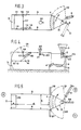
- Some embodiments of the feeding station according to the present invention will now be described, by way of example, with reference to the accompanying drawings, in which:
- Fig. 1 is a diagrammatic top view of a prior art feeding station;
- Fig. 2 is a lateral view of the feeding station of Fig. 1;
- Fig. 3 is a diagrammatic top view of a first embodiment of a feeding station according to the present invention;
- Fig. 4 is a lateral view of the feeding station of Fig. 3; and
- Fig. 5 is a diagrammatic top view of a second embodiment of a feeding station according to the present invention.
- The prior art station shown in Figs. 1 and 2 comprises a
stationary feeding trough 1 from which fodder can be eaten, with asuperimposed dispenser 2 and asupply container 3. By means of theradiographic detector 4, the animal, e.g. a pig, wearing e.g. a collar with a detection means (a so- called responder) is identified, since this responder, arriving in the vicinity of the electromagnetic interrogation field ofdetector 4, will transmit a code uniqueforthe animal concerned. This code is processed in a computer so that it is decided automatically, in a manner predetermined by the cattle breeder, whether the animal is entitled to any fodder, and if so, how much, after which the dispensing of the fodder can be started. - In order to prevent the eating animal from being disturbed, such a feeding station is usually fitted with two
side walls entrance door 7, which is closed as soon as the animal is present within the feeding box thus produced. - When the animal has finished eating, the
entrance door 7 will be opened under computer control, with the animal leaving the feeding station in backward direction. - Figs. 3 and 4 show a first embodiment of a feeding station according to the present invention. The station shown includes again
side walls feeding trough 30 disposed at the one end, said trough having again adetector 4 for a responder. At the entrance end of the feeding station there is provided in this embodiment a door31, which may be constructed as a single door, two half-doors, one hanging door or as a sliding door. In the embodiment shown, use is made of a specially formed door which occupies little space and which will be further described hereinafter. - The
feeding trough 30 in this embodiment, as seen in top view, has a substantially triangular form the front of which, proximal to the feeding station, as shown, may have a curved shape and has an entrance opening for the head of an animal. At the apex of the triangular feeding trough, distal from the feeding station, it is mounted for pivotal movement about avertical shaft 8. In the eating position, the feeding trough entirely closes the feeding station and the fodder present in the trough is accessible to an animal present in the feeding station. - It is observed that the front of the trough may alternatively have a smaller width than the width of the feeding station, in which case it would be incorporated in an end wall further shutting off the feeding station.
- The trough is also connected to an
operating member 9 which, as shown, may be a hydraulic or pneumatic cylinder which, on energization will rotate the trough about thevertical shaft 8 into such a position that an animal present in the feeding station can leave the station in forward direction. Such a position is shown at 10 in broken lines. In this position, the fodder is out of reach of the animal. Preferably, the side walls of the trough are closed, so that any fodder remaining in the trough is no longer visible to the animal, so that it will leave the feeding station rapidly. -
Operating member 9 is energized preferably automatically e.g. under computer control. For instance, the operating member can be energized a predetermined period of time after an animal present in the feeding station has been identified and the fodder has been supplied to the trough, so as to open the exit of the station. The predetermined period of time, if desired, may depend on the quantity of fodder received by the animal. Subsequently, e.g. after a second predetermined period of time, the trough may be returned to the closing position, while at the same time the entrance of the feeding station is opened. - The closing of the exit and the opening of the entrance, if desired, may also be controlled, starting from signals provided by a separate detector arranged adjacent the exit of the station. To this effect, e.g. a light barrier or a depression contact may be disposed in the floor in the path of exit of the animal. Such a light barrier is indicated diagrammatically at 32 in Fig. 3.
- It is observed that the
fodder supply device vertical shaft 8. - It is further observed that the exit of the feeding station may alternatively be arranged to be cleared by sliding the trough along the
vertical shaft 8 in upward direction. - According to a preferred embodiment of the feeding station according to the present invention, the entrance is provided with an
access door 31 as shown in Fig. 4.Door 31 includes a bent plate attached toarms side walls pivots Door 31 can be swung upwards into theposition 15 shown in broken lines, e.g. moved by anair cylinder 16. To teach the animal to leave the feeding box quickly, one or more dependingchains 17 may be fitted on across rod 18 to which, after a given delay period, short, harmless voltage pulses are applied as in an electricfence installation. The animal could also be pushed on mechanically to ensure that it leaves the feeding box. - Besides, the feeding station shown may be provided with a marker, e.g. consisting of a
dye container 20,electric magnet valve 21 andoutlet 22.Valve 21 can be opened through computer control so that the animal then present in the feeding box receives a colour mark, allowing it to be separated subsequently from the herd, e.g. in connection with the state of fertility of the animal. A further extension of the feeding station shown may be aliquid dispenser 23, by means of which a liquid (e.g. water) is supplied via amagnet valve 24 to the usually solid fodder. This increases the eating speed considerably, while also feedingtrough 1 remains cleaner, thereby preventing fodder rests from getting mouldy. - Fig. 5 shows an embodiment similar to that of Fig. 3 with the added possibility of separating the animals. The feeding
trough 30 can now not only be moved intoposition 10 but also into asecond position 25, e.g. by means of theair cylinder 9. When the cattle house is divided into three parts A, B and C by means of partitions orfences position 25 or inposition 10. In this manner e.g. fertile or sick animals can be isolated from the rest of the herd by computer control. - Naturally, this station, too can be provided with an ousting
device marker liquid dispenser filler 29 can be attached against thedoor 7 in a simple manner, e.g. by means of screwed bolts with wing nuts. This filler extends along at least a part of the height of the door. By using fillers of different depths a (obtained possibly by adjustability) the effective length d of the station can be adjusted as desired. - Also the width b of the feeding station can be made adjustable, if desired, in an otherwise known manner not further indicated by
rendering partitions 5 and/or 6 movable in the width direction b of the station. - The feeding station described makes it possible to effectively feed animals partly or entirely automatically, with a short eating cycle, so that relatively many animals can be fed with one feeding station. After the above description, various modifications are obvious to one skilled in the art, which are deemed to fall within the scope of the present invention.
Claims (17)
Priority Applications (1)
| Application Number | Priority Date | Filing Date | Title |
|---|---|---|---|
| AT86200996T ATE56347T1 (en) | 1985-06-10 | 1986-06-09 | FEEDING STATION FOR CATTLE. |
Applications Claiming Priority (2)
| Application Number | Priority Date | Filing Date | Title |
|---|---|---|---|
| NL8501662A NL8501662A (en) | 1985-06-10 | 1985-06-10 | FEEDING STATION FOR CATTLE. |
| NL8501662 | 1985-06-10 |
Publications (2)
| Publication Number | Publication Date |
|---|---|
| EP0205219A1 EP0205219A1 (en) | 1986-12-17 |
| EP0205219B1 true EP0205219B1 (en) | 1990-09-12 |
Family
ID=19846110
Family Applications (1)
| Application Number | Title | Priority Date | Filing Date |
|---|---|---|---|
| EP86200996A Expired - Lifetime EP0205219B1 (en) | 1985-06-10 | 1986-06-09 | A cattle feeding station |
Country Status (6)
| Country | Link |
|---|---|
| US (1) | US4753194A (en) |
| EP (1) | EP0205219B1 (en) |
| AT (1) | ATE56347T1 (en) |
| CA (1) | CA1259864A (en) |
| DE (1) | DE3674072D1 (en) |
| NL (1) | NL8501662A (en) |
Families Citing this family (8)
| Publication number | Priority date | Publication date | Assignee | Title |
|---|---|---|---|---|
| DE3701864A1 (en) * | 1987-01-23 | 1988-08-04 | Buschhoff Th Ag | Arrangement for request feeding of pigs |
| AT401706B (en) * | 1993-02-02 | 1996-11-25 | Vogl Gerhard | PIG FEEDING SYSTEM |
| NL1013208C2 (en) * | 1999-10-04 | 2001-04-05 | Skiold Nederland B V | Measurement sluice for fattened cattle has one closable inlet providing access to measurement chamber containing at least one measurement device for determining at least one magnitude |
| FR2862186B1 (en) * | 2003-11-14 | 2006-03-10 | Thierry Dessoliere | RACK |
| NL1031575C2 (en) * | 2006-04-12 | 2007-10-15 | Maasland Nv | Method and device for feeding an animal in a feed box. |
| AU2017366311B2 (en) | 2016-11-24 | 2022-12-01 | Delaval Holding Ab | A milking stable |
| CN107135968A (en) * | 2017-05-18 | 2017-09-08 | 中国农业科学院北京畜牧兽医研究所 | A kind of milch goat accurate feeding station |
| US20200100458A1 (en) * | 2018-09-27 | 2020-04-02 | Don GIBSON | Methods and Systems for Efficient Milking of Cows |
Family Cites Families (20)
| Publication number | Priority date | Publication date | Assignee | Title |
|---|---|---|---|---|
| NL102079C (en) * | 1954-12-27 | |||
| US2858800A (en) * | 1954-12-27 | 1958-11-04 | Babson Bros Co | Lane-type stall |
| DE1607157A1 (en) * | 1966-06-29 | 1970-07-09 | Belokon Vladimir S | Milking parlor |
| NL6610164A (en) * | 1966-07-19 | 1968-01-22 | ||
| US3448725A (en) * | 1968-04-29 | 1969-06-10 | Holm Tractor & Equipment Co | Milking stall |
| US3792686A (en) * | 1972-06-13 | 1974-02-19 | Babson Bros Co | Cow preparation stall for milking parlors |
| US3805742A (en) * | 1972-08-14 | 1974-04-23 | Babson Bros Co | Milking stall with forcer gate |
| US4010714A (en) * | 1974-03-08 | 1977-03-08 | Director, National Institute Of Animal Industry | System for managing milking-cows in stanchion stool |
| FR2288460A1 (en) * | 1974-08-09 | 1976-05-21 | Anvar | ANIMALS SUCH AS COWS MILKING FACILITIES |
| GB1577920A (en) * | 1976-11-01 | 1980-10-29 | Nedap Nv | Detection plate for identification systems |
| US4129096A (en) * | 1977-01-07 | 1978-12-12 | Nickel Lonnie L | Sow feeding enclosure |
| US4182273A (en) * | 1978-02-23 | 1980-01-08 | Peterson Maurice L | Feeding apparatus |
| DE2813882A1 (en) * | 1978-03-31 | 1979-10-04 | Horst Feld | Animal positioning device for stalls - consists of wire movable between raised and lowered positions to allow movement to feed troughs or hold animals over manure channel |
| US4362127A (en) * | 1981-06-18 | 1982-12-07 | Nielsen Industries, Inc. | Milking barn system and apparatus |
| NL8104289A (en) * | 1981-09-17 | 1983-04-18 | Johannes Joseph Maria Van Else | DEVICE FOR APPLYING SIGNS TO AN OBJECT, IN PARTICULAR FOR BRANDING LIVE OR DEAD ANIMALS. |
| NL8104575A (en) * | 1981-10-08 | 1983-05-02 | Hendrik Pol | Milking stall with traVelling access bridge - has lower-level platform on bridge forming working space for cowman |
| SE430559B (en) * | 1982-04-08 | 1983-11-28 | Alfa Laval Ab | SET FOR MILK AND DEVICE HERE |
| US4419961A (en) * | 1982-04-16 | 1983-12-13 | August Vandenberg | Milking parlor construction |
| US4508059A (en) * | 1984-02-10 | 1985-04-02 | Nielsen Industries, Inc. | Milking barn |
| US4617876A (en) * | 1984-11-28 | 1986-10-21 | Hayes Norman J | Animal identification and control system |
-
1985
- 1985-06-10 NL NL8501662A patent/NL8501662A/en not_active Application Discontinuation
-
1986
- 1986-06-06 US US06/871,446 patent/US4753194A/en not_active Expired - Lifetime
- 1986-06-09 AT AT86200996T patent/ATE56347T1/en not_active IP Right Cessation
- 1986-06-09 CA CA000511145A patent/CA1259864A/en not_active Expired
- 1986-06-09 DE DE8686200996T patent/DE3674072D1/en not_active Expired - Lifetime
- 1986-06-09 EP EP86200996A patent/EP0205219B1/en not_active Expired - Lifetime
Also Published As
| Publication number | Publication date |
|---|---|
| US4753194A (en) | 1988-06-28 |
| NL8501662A (en) | 1987-01-02 |
| ATE56347T1 (en) | 1990-09-15 |
| CA1259864A (en) | 1989-09-26 |
| DE3674072D1 (en) | 1990-10-18 |
| EP0205219A1 (en) | 1986-12-17 |
Similar Documents
| Publication | Publication Date | Title |
|---|---|---|
| US5309864A (en) | Method and apparatus for feeding animals | |
| US4672917A (en) | Feeder | |
| EP0772389B1 (en) | Device and method for automatically milking of amimals | |
| US6526919B1 (en) | Self-sorting hog facility and method | |
| EP0194729A1 (en) | Implement for milking animals | |
| EP0830055B2 (en) | A construction including an implement for milking animals | |
| AU721594B2 (en) | Dairy parlor entry gate | |
| PL200846B1 (en) | Arrangement for individual feeding of free-range animals | |
| US4815417A (en) | Brooder feeding apparatus | |
| US4753194A (en) | Cattle feeding station | |
| KR20120022035A (en) | Hog mix feeder | |
| EP1698227A2 (en) | A device for and a method of automatically supplying feed to animals | |
| EP1145627B1 (en) | A feed metering device | |
| JP2002272299A (en) | Equipment and method for tending livestock group | |
| GB1564197A (en) | Fodder distributing | |
| US3850145A (en) | Supplemental feeder | |
| CN116076390A (en) | Trestle type breeding duck measuring equipment, trestle type breeding duck measuring system and trestle type breeding duck training method | |
| EP0897261B1 (en) | A device and method for milking animals | |
| HU187908B (en) | Feeding stall | |
| EP0257039A1 (en) | Installation for pig production | |
| CN218897566U (en) | Trestle type breeding duck measuring equipment and measuring system | |
| NL9000974A (en) | METHOD FOR MAKING ANIMALS RECOGNIZABLE BY AN ELECTRONIC CODE CARRIER IN A SPECIAL PLACE, INCLUDING DETECTION SYSTEMS DESIGNED THEREOF. | |
| EP0449901A1 (en) | Method and apparatus for marking and/or dispensing medicinal treatment in the form of a substance, such as powder, paste or liquid, to a wild animal | |
| EP0260263B1 (en) | Animal box | |
| CA1138275A (en) | Automatic feeding apparatus |
Legal Events
| Date | Code | Title | Description |
|---|---|---|---|
| PUAI | Public reference made under article 153(3) epc to a published international application that has entered the european phase |
Free format text: ORIGINAL CODE: 0009012 |
|
| AK | Designated contracting states |
Kind code of ref document: A1 Designated state(s): AT BE CH DE FR GB IT LI NL SE |
|
| 17P | Request for examination filed |
Effective date: 19870204 |
|
| 17Q | First examination report despatched |
Effective date: 19890120 |
|
| ITF | It: translation for a ep patent filed | ||
| GRAA | (expected) grant |
Free format text: ORIGINAL CODE: 0009210 |
|
| AK | Designated contracting states |
Kind code of ref document: B1 Designated state(s): AT BE CH DE FR GB IT LI NL SE |
|
| REF | Corresponds to: |
Ref document number: 56347 Country of ref document: AT Date of ref document: 19900915 Kind code of ref document: T |
|
| REF | Corresponds to: |
Ref document number: 3674072 Country of ref document: DE Date of ref document: 19901018 |
|
| ET | Fr: translation filed | ||
| ITTA | It: last paid annual fee | ||
| PLBE | No opposition filed within time limit |
Free format text: ORIGINAL CODE: 0009261 |
|
| STAA | Information on the status of an ep patent application or granted ep patent |
Free format text: STATUS: NO OPPOSITION FILED WITHIN TIME LIMIT |
|
| 26N | No opposition filed | ||
| PGFP | Annual fee paid to national office [announced via postgrant information from national office to epo] |
Ref country code: SE Payment date: 19930630 Year of fee payment: 8 Ref country code: AT Payment date: 19930630 Year of fee payment: 8 |
|
| PGFP | Annual fee paid to national office [announced via postgrant information from national office to epo] |
Ref country code: BE Payment date: 19930728 Year of fee payment: 8 |
|
| PGFP | Annual fee paid to national office [announced via postgrant information from national office to epo] |
Ref country code: CH Payment date: 19930923 Year of fee payment: 8 |
|
| PGFP | Annual fee paid to national office [announced via postgrant information from national office to epo] |
Ref country code: GB Payment date: 19940601 Year of fee payment: 9 |
|
| PG25 | Lapsed in a contracting state [announced via postgrant information from national office to epo] |
Ref country code: AT Effective date: 19940609 |
|
| PG25 | Lapsed in a contracting state [announced via postgrant information from national office to epo] |
Ref country code: SE Effective date: 19940610 |
|
| PGFP | Annual fee paid to national office [announced via postgrant information from national office to epo] |
Ref country code: FR Payment date: 19940627 Year of fee payment: 9 |
|
| PG25 | Lapsed in a contracting state [announced via postgrant information from national office to epo] |
Ref country code: LI Effective date: 19940630 Ref country code: CH Effective date: 19940630 Ref country code: BE Effective date: 19940630 |
|
| PGFP | Annual fee paid to national office [announced via postgrant information from national office to epo] |
Ref country code: NL Payment date: 19940630 Year of fee payment: 9 |
|
| BERE | Be: lapsed |
Owner name: NEDERLANDSCHE APPARATENFABRIEK NEDAP N.V. Effective date: 19940630 |
|
| EUG | Se: european patent has lapsed |
Ref document number: 86200996.6 Effective date: 19950110 |
|
| REG | Reference to a national code |
Ref country code: CH Ref legal event code: PL |
|
| EUG | Se: european patent has lapsed |
Ref document number: 86200996.6 |
|
| PG25 | Lapsed in a contracting state [announced via postgrant information from national office to epo] |
Ref country code: GB Effective date: 19950609 |
|
| PG25 | Lapsed in a contracting state [announced via postgrant information from national office to epo] |
Ref country code: NL Effective date: 19960101 |
|
| GBPC | Gb: european patent ceased through non-payment of renewal fee |
Effective date: 19950609 |
|
| PG25 | Lapsed in a contracting state [announced via postgrant information from national office to epo] |
Ref country code: FR Effective date: 19960229 |
|
| NLV4 | Nl: lapsed or anulled due to non-payment of the annual fee |
Effective date: 19960101 |
|
| REG | Reference to a national code |
Ref country code: FR Ref legal event code: ST |
|
| PG25 | Lapsed in a contracting state [announced via postgrant information from national office to epo] |
Ref country code: IT Free format text: LAPSE BECAUSE OF NON-PAYMENT OF DUE FEES Effective date: 20050609 |
|
| PGFP | Annual fee paid to national office [announced via postgrant information from national office to epo] |
Ref country code: DE Payment date: 20050718 Year of fee payment: 20 |