EP0204727B1 - A drive mechanism for axial movement of a rod, in particular an infusion pump - Google Patents
A drive mechanism for axial movement of a rod, in particular an infusion pump Download PDFInfo
- Publication number
- EP0204727B1 EP0204727B1 EP85905608A EP85905608A EP0204727B1 EP 0204727 B1 EP0204727 B1 EP 0204727B1 EP 85905608 A EP85905608 A EP 85905608A EP 85905608 A EP85905608 A EP 85905608A EP 0204727 B1 EP0204727 B1 EP 0204727B1
- Authority
- EP
- European Patent Office
- Prior art keywords
- drive
- worm
- rod
- worms
- drive mechanism
- Prior art date
- Legal status (The legal status is an assumption and is not a legal conclusion. Google has not performed a legal analysis and makes no representation as to the accuracy of the status listed.)
- Expired
Links
- 230000007246 mechanism Effects 0.000 title claims abstract description 28
- 238000001802 infusion Methods 0.000 title description 12
- 239000000463 material Substances 0.000 claims abstract description 14
- 238000002347 injection Methods 0.000 claims abstract 2
- 239000007924 injection Substances 0.000 claims abstract 2
- 230000035515 penetration Effects 0.000 claims description 4
- 238000006073 displacement reaction Methods 0.000 claims description 3
- 230000001154 acute effect Effects 0.000 claims description 2
- 230000007423 decrease Effects 0.000 claims description 2
- 230000000694 effects Effects 0.000 abstract description 2
- 230000005540 biological transmission Effects 0.000 description 9
- NOESYZHRGYRDHS-UHFFFAOYSA-N insulin Chemical compound N1C(=O)C(NC(=O)C(CCC(N)=O)NC(=O)C(CCC(O)=O)NC(=O)C(C(C)C)NC(=O)C(NC(=O)CN)C(C)CC)CSSCC(C(NC(CO)C(=O)NC(CC(C)C)C(=O)NC(CC=2C=CC(O)=CC=2)C(=O)NC(CCC(N)=O)C(=O)NC(CC(C)C)C(=O)NC(CCC(O)=O)C(=O)NC(CC(N)=O)C(=O)NC(CC=2C=CC(O)=CC=2)C(=O)NC(CSSCC(NC(=O)C(C(C)C)NC(=O)C(CC(C)C)NC(=O)C(CC=2C=CC(O)=CC=2)NC(=O)C(CC(C)C)NC(=O)C(C)NC(=O)C(CCC(O)=O)NC(=O)C(C(C)C)NC(=O)C(CC(C)C)NC(=O)C(CC=2NC=NC=2)NC(=O)C(CO)NC(=O)CNC2=O)C(=O)NCC(=O)NC(CCC(O)=O)C(=O)NC(CCCNC(N)=N)C(=O)NCC(=O)NC(CC=3C=CC=CC=3)C(=O)NC(CC=3C=CC=CC=3)C(=O)NC(CC=3C=CC(O)=CC=3)C(=O)NC(C(C)O)C(=O)N3C(CCC3)C(=O)NC(CCCCN)C(=O)NC(C)C(O)=O)C(=O)NC(CC(N)=O)C(O)=O)=O)NC(=O)C(C(C)CC)NC(=O)C(CO)NC(=O)C(C(C)O)NC(=O)C1CSSCC2NC(=O)C(CC(C)C)NC(=O)C(NC(=O)C(CCC(N)=O)NC(=O)C(CC(N)=O)NC(=O)C(NC(=O)C(N)CC=1C=CC=CC=1)C(C)C)CC1=CN=CN1 NOESYZHRGYRDHS-UHFFFAOYSA-N 0.000 description 8
- 229920003023 plastic Polymers 0.000 description 6
- 239000004033 plastic Substances 0.000 description 6
- 238000009499 grossing Methods 0.000 description 5
- 102000004877 Insulin Human genes 0.000 description 4
- 108090001061 Insulin Proteins 0.000 description 4
- 229940125396 insulin Drugs 0.000 description 4
- 229910000831 Steel Inorganic materials 0.000 description 2
- 239000012535 impurity Substances 0.000 description 2
- 238000004519 manufacturing process Methods 0.000 description 2
- 239000010959 steel Substances 0.000 description 2
- 230000004323 axial length Effects 0.000 description 1
- 230000000903 blocking effect Effects 0.000 description 1
- 238000004140 cleaning Methods 0.000 description 1
- 206010012601 diabetes mellitus Diseases 0.000 description 1
- 239000003814 drug Substances 0.000 description 1
- 238000005265 energy consumption Methods 0.000 description 1
- 230000007774 longterm Effects 0.000 description 1
- 238000001228 spectrum Methods 0.000 description 1
Images



Classifications
-
- A—HUMAN NECESSITIES
- A61—MEDICAL OR VETERINARY SCIENCE; HYGIENE
- A61M—DEVICES FOR INTRODUCING MEDIA INTO, OR ONTO, THE BODY; DEVICES FOR TRANSDUCING BODY MEDIA OR FOR TAKING MEDIA FROM THE BODY; DEVICES FOR PRODUCING OR ENDING SLEEP OR STUPOR
- A61M5/00—Devices for bringing media into the body in a subcutaneous, intra-vascular or intramuscular way; Accessories therefor, e.g. filling or cleaning devices, arm-rests
- A61M5/14—Infusion devices, e.g. infusing by gravity; Blood infusion; Accessories therefor
- A61M5/142—Pressure infusion, e.g. using pumps
- A61M5/145—Pressure infusion, e.g. using pumps using pressurised reservoirs, e.g. pressurised by means of pistons
- A61M5/1452—Pressure infusion, e.g. using pumps using pressurised reservoirs, e.g. pressurised by means of pistons pressurised by means of pistons
- A61M5/1456—Pressure infusion, e.g. using pumps using pressurised reservoirs, e.g. pressurised by means of pistons pressurised by means of pistons with a replaceable reservoir comprising a piston rod to be moved into the reservoir, e.g. the piston rod is part of the removable reservoir
-
- F—MECHANICAL ENGINEERING; LIGHTING; HEATING; WEAPONS; BLASTING
- F04—POSITIVE - DISPLACEMENT MACHINES FOR LIQUIDS; PUMPS FOR LIQUIDS OR ELASTIC FLUIDS
- F04B—POSITIVE-DISPLACEMENT MACHINES FOR LIQUIDS; PUMPS
- F04B9/00—Piston machines or pumps characterised by the driving or driven means to or from their working members
- F04B9/02—Piston machines or pumps characterised by the driving or driven means to or from their working members the means being mechanical
Definitions
- the invention concerns a drive mechanism for axial movement of a rod, in particular a plunger rod for an infusion pump.
- a plunger rod for an infusion pump for example the British Patent Specification 2 077 599 discloses an automatic infusion pump to receive an infusion syringe, said pump comprising a battery and a control circuit for a motor driving a gear which drives an axially grooved drive wheel whose axis of rotation is perpendicular to the plunger rod of the infusion syringe.
- the plunger rod is pressed against the drive wheel so that the cams of said wheel penetrate into the plunger rod consisting of plastics which is cold deformed by the penetration of the cams.
- this known apparatus can give a tolerance of about 5 % of the injected amount per unit of time when the unit of time is of the order of several hours.
- medicaments e.g. insulin
- the pump should be as compact as possible, and this entails in practice that the diameter of the known drive wheel is about 5 mm and that an average of four of its about 30 cams or teeth engage the plunger rod.
- the drive wheel is only to rotate about 1/200 of an entire revolution for the pump to deliver an international unit of insulin, and it will therefore be appreciated that the desired accuracy is difficult to obtain since not only are huge requirements made of the tolerance of the drive wheel tooth cross-section, but also any inhomogeneity in the plunger rod material affects the deformation of the material by each tooth during the entire travel thereof through the material. It will moreover be appreciated that also variations in the effective pitch diameter of the drive wheel because of e.g. eccentricity, bearing wear or impurities in the bottom of the axial grooves of the wheel greatly affect the accuracy of the apparatus.
- the object of the invention is to provide a drive mechanism of the above-mentioned type which significantly improves the accuracy over the prior art, while no huge tolerance requirements are made of the gear transmission of the mechanism.
- the relative or short term accuracy is improved since each track formed by the worm threads in the plunger rod has a constant cross-section over a substantial portion of the engagement between the track and the worm, and since more thread flanks than in the prior art engage the rod material, axial flowing of the rod material because of the counter pressure of the plunger rod will be less pronounced.
- the absolute or long term accuracy is improved because the transmission does not depend upon a pitch diameter, but only upon the pitch of the worm threads.
- the worm mechanism is self-cleaning, and that the large transmission allows the other toothed wheels of the gear transmission to be manufactured with small tolerance requirements and optionally to be plastics moulded.
- the friction between the worms and the plunger rod has been found to be relatively great with respect to the energy consumption for the advance of the plunger rod, and particularly in case of mechanisms driven by batteries it is desirable to reduce the frictional energy. This can be obtained by reducing the axial length of the drive worms, whereby, however, the displacement of the plunger rod material will have a relatively great influence on the accuracy, which accordingly varies with the rotation of the drive worms. Since the invention also comprises smoothing of this variation, the characterizing portion of claim 1 sets forth a combination of features providing a significantly greater accuracy with respect to the prior art.
- the smoothing of the thread inlet is preferably obtained by mutual angular displacement.
- the embodiment defined in claim 3 is preferably used, and this embodiment also entails that the plunger rod is wedged down between the drive worms.
- Claim 4 defines alternative features for smoothing of the worm thread inlet so that the metering accuracy is not affected by discontinuous thread inlets.
- the thread inlet may be made additionally even by making the drive worms single conical or double conical.
- the single conical form stated in claim 5 involves a noticeable advantage at the thread inlet, while the double conical form stated in claim 6 also involves smoothing of the thread outlet.
- Claim 8 defines details in a preferred embodiment which is particularly inexpensive to manufacture, in particular for infusion syringes.
- the invention provides the additional advantage that the counter pressure caused by blocking or by homing of the infusion syringe plunger is transformed to a force which is substantially parallel with the axis of the worm, and which is therefore easy to detect, e.g. by means of the features stated in claim 9.
- the known structure shown in fig. 1 comprises a housing 1 with a cavity 2 to receive a carpule 3 for an infusion syringe, which moreover comprises a plunger 4 and an associated plunger rod 5 preferably made of plastics.
- the numeral 6 designates a slide which in the extended position allows the carpule and the plunger rod to be received in the apparatus, following which the slide can be pushed into position, as appears from fig. 2.
- the slide 6 is arranged to urge the plunger rod 5 down toward a drive roller 7 driven by a motor in the housing 1 via a gear.
- Teh apparatus is designed to be carried by a patient, e.g. a diabetic, and the infusion syringe is connected via a plastic hose with a needle inserted into the patient. It is therefore disirable that the apparatus is as compact as possible, and that metering as accurate as possible can be obtained.
- the drive roller 7 is only about 5 mm in diameter (see fig. 3), and for the apparatus to dispense an international unit of insulin the roller is just to be rotated about 1/200 of an entire revolution. Since only few teeth of the roller 7 are engaged with the plunger rod 5, it is very difficult with this art to obtain an accuracy of about 5 %, based on an insulin unit. There are several sources of inaccuracy, one of them being that each of the drive roller teeth works into the plunger rod 5 by cold deformation of it, said cold deformation continuing over the entire travel of the tooth through the materail.
- the transmission ratio depends on a pitch diameter, which varies with the function of the depth of tooth penetration into the plunger rod, and it will therefore be appreciated that impurities in the bottom of the teeth, like drive roller bearing wear, affects the accuracy. All these drawbacks are remedied by the mechanism of the invention, a preferred embodiment of whcih is shown in figs. 4 - 6.
- figs. 4 - 6 are taken of an apparatus which might otherwise be constructed as explained in connection with figs. 1 and 2.
- the numerals 9 and 10 designate the top side and the underside, respectively, of a housing of the type shown in fig. 1.
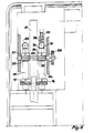
- Fig. 4 shows a section through the housing, a plunger rod 11 being visible which is placed in the apparatus together with the associated plunger 14 and the carpule 13.
- a roller 12 serves to press the plunger rod 11 down between two worm wheels 15,16 (fig.
- each of the worm wheels 15, 16 is placed on an associated shaft 19, 20 rotated in opposite directions of rotation by means of a common worm or toothed wheel gear. More particularly, the shaft 19 has a helical toothed wheel 21 which is driven by a toothed wheel 22, which is in turn attached to a shaft 23 supporting an additional worm wheel 24 driving the shaft 20. As appears from the arrows in fig. 5, the worms 15, 16 ar driven in opposite directions, thereby preventing the plunger rod 11 from being subjected to a rotational force.
- the shaft 23 is driven via a toothed wheel 28 via an additional gear transmission by a motot, which is schematically shown at 26.
- Fig. 6 is a schematic bottom view of the mechanism of fig. 5, showing clearly the engagement between the wheels nemtioned in connection with fig 5 and the plunger rod 11. Because of the large transmission in the worms, it will be appreciated that the (not shown) toothed wheels in the gear transmission between the toothed wheel 28 and the motor 26 can be made of plastics.
- Fig. 6 moreover shows a pair of embodiments of pressure bearings for the shafts 19 and 20, respectively.
- the shaft 19 can be journalled like the shaft 20, but, in the drawing, it is journalled against a fixed steel ball 29. If the needle should be blocked, or the plunger 14 has bottomed in the carpule 13, a strong counter pressure will be generated in parallel with the shafts 19, 20, which can be detected by means of the pressure bearing embodiment shown in fig. 6 for the shaft 20.
- the latter pressure bearing comprises a seat rim 30 for the steel ball 31, which is pressed against this seat by means of a spring 32 whose spring force is adjustable by means of a screw 33.
- the transmission ratio is very well- defined and depends upon the pitch of the threads on the worms 15, 16, independent of the depth of penetration of the threads into the plunger rod 11.
- the thread inlet and outlet problems have also been mentioned before, but it has been found in practice that the described embodiment involves a suitable reduction in the action upon the thread inlets in that the thread inlets are mutually angularly displaced, which means that the beginning of the threads (34, 35 in fig. 5) is mutually rotated through an angle of 180°.
- the envelopes of the threads are conical, the vertex being in the direction of the carpule, and the included angle being just a few degrees.
- the combination of this slightly expanding pitch diameter and the angularly displaced inlets has been found to be particularly advantageous. Corresponding measures may also be taken in connection with the thread outlets, but this is not necessary to obtain the desired accuracy in practice.
- Fig. 7 shows an explanatory sketch of an embodiment comprising three worm wheels 36, 37, 38 designed to drive a plunger rod 39.
- the plunger rod 39 might be made of a hard material on whose exterior a sleeve 40 of a cold deformable material is placed.
- the embodiment shown in fig. 7 is not suitable in connection with the slide described previously, but is useful in a mechanism where the plunger rod is introduced axially with respect to the drive worms 36-38. Provision of several worms results in further smoothing of the inlets, merely by displacing these mutually in an angle of about 120° when three worms are provided.
- Fig. 8 is a schematic view of an embodiment in which the axis of rotation of the worm 41 forms an acute angle with the plunger rod 42.
- the thread 43 is shown with a very great pitch for clarity, and when the axis of rotation of the worm is rotated through the said angle the threads form grooves in the plunger rod 42, said grooves being perpendicular to the plunger rod so that the drive force on the plunger rod 42 is approximately parallel with the direction of movement of the plunger.
- the numeral 44 designates the grooves produced by the thread 43 in the plunger rod 42, and when the worm 41 extends beyond the area where it cooperates with the plunger rod 42, discoutinuous thread inlet and outlet can be obtained, which is symbolized by the solid lines on the worm, these lines representing the extent of the thread cooperation with the plunger rod 42.
- Fig. 9 shows an additional embodiment of a worm mechanism of the invention, where it can be seen that the worm 45 has a barrel-shaped cross-section, which means that the diameter of the threads is greatest at the centre and decreases toward the ends of the worm.
- the plunger rod is represented at 46, and it will therefore readily be seen that the grooves 47 in the plunger rod are produced continuously as the worm 45 rotates, and the thread emerges continuously and evenly from the grooves 47.
Landscapes
- Engineering & Computer Science (AREA)
- Health & Medical Sciences (AREA)
- Public Health (AREA)
- Veterinary Medicine (AREA)
- Biomedical Technology (AREA)
- Heart & Thoracic Surgery (AREA)
- Hematology (AREA)
- Life Sciences & Earth Sciences (AREA)
- Animal Behavior & Ethology (AREA)
- General Health & Medical Sciences (AREA)
- Vascular Medicine (AREA)
- Anesthesiology (AREA)
- Mechanical Engineering (AREA)
- General Engineering & Computer Science (AREA)
- Infusion, Injection, And Reservoir Apparatuses (AREA)
- Reciprocating Pumps (AREA)
- Pistons, Piston Rings, And Cylinders (AREA)
- Fluid-Damping Devices (AREA)
- Shaping Metal By Deep-Drawing, Or The Like (AREA)
- Pens And Brushes (AREA)
Abstract
Description
- The invention concerns a drive mechanism for axial movement of a rod, in particular a plunger rod for an infusion pump. For example the British Patent Specification 2 077 599 discloses an automatic infusion pump to receive an infusion syringe, said pump comprising a battery and a control circuit for a motor driving a gear which drives an axially grooved drive wheel whose axis of rotation is perpendicular to the plunger rod of the infusion syringe. In this known apparatus the plunger rod is pressed against the drive wheel so that the cams of said wheel penetrate into the plunger rod consisting of plastics which is cold deformed by the penetration of the cams.
- Provided that the gear has been manufactured with great accuracy, this known apparatus can give a tolerance of about 5 % of the injected amount per unit of time when the unit of time is of the order of several hours. In certain medicaments, e.g. insulin, however, it is desirable to obtain a corresponding metering accuracy even if the mentioned unit of time is only about one hour. Since the patient carries the infusion pump on him, the pump should be as compact as possible, and this entails in practice that the diameter of the known drive wheel is about 5 mm and that an average of four of its about 30 cams or teeth engage the plunger rod. Further, the drive wheel is only to rotate about 1/200 of an entire revolution for the pump to deliver an international unit of insulin, and it will therefore be appreciated that the desired accuracy is difficult to obtain since not only are huge requirements made of the tolerance of the drive wheel tooth cross-section, but also any inhomogeneity in the plunger rod material affects the deformation of the material by each tooth during the entire travel thereof through the material. It will moreover be appreciated that also variations in the effective pitch diameter of the drive wheel because of e.g. eccentricity, bearing wear or impurities in the bottom of the axial grooves of the wheel greatly affect the accuracy of the apparatus.
- The object of the invention is to provide a drive mechanism of the above-mentioned type which significantly improves the accuracy over the prior art, while no huge tolerance requirements are made of the gear transmission of the mechanism.
- This object is achieved by the use of a worm drive, as stated in the characterizing portion of
claim 1, because precisely the use of a worm drive known per se for an apparatus, in which the flanks of one or more worm threads penetrate evenly into the rod material by cold deformation thereof, provides more and surprising advantages than those already known in connection with non-self-cutting worm gears. - First, the relative or short term accuracy is improved since each track formed by the worm threads in the plunger rod has a constant cross-section over a substantial portion of the engagement between the track and the worm, and since more thread flanks than in the prior art engage the rod material, axial flowing of the rod material because of the counter pressure of the plunger rod will be less pronounced. Second, also the absolute or long term accuracy is improved because the transmission does not depend upon a pitch diameter, but only upon the pitch of the worm threads. Finally, it may be stated that the worm mechanism is self-cleaning, and that the large transmission allows the other toothed wheels of the gear transmission to be manufactured with small tolerance requirements and optionally to be plastics moulded.
- The friction between the worms and the plunger rod has been found to be relatively great with respect to the energy consumption for the advance of the plunger rod, and particularly in case of mechanisms driven by batteries it is desirable to reduce the frictional energy. This can be obtained by reducing the axial length of the drive worms, whereby, however, the displacement of the plunger rod material will have a relatively great influence on the accuracy, which accordingly varies with the rotation of the drive worms. Since the invention also comprises smoothing of this variation, the characterizing portion of
claim 1 sets forth a combination of features providing a significantly greater accuracy with respect to the prior art. - As stated in claim 2, the smoothing of the thread inlet is preferably obtained by mutual angular displacement. To obtain equilibrium for lateral forces, the embodiment defined in
claim 3 is preferably used, and this embodiment also entails that the plunger rod is wedged down between the drive worms. - Claim 4 defines alternative features for smoothing of the worm thread inlet so that the metering accuracy is not affected by discontinuous thread inlets.
- The thread inlet may be made additionally even by making the drive worms single conical or double conical. The single conical form stated in claim 5 involves a noticeable advantage at the thread inlet, while the double conical form stated in claim 6 also involves smoothing of the thread outlet.
- The effect of discontinuous inlets and outlets can be further reduced by the features defined in claim 7, which require the presence of two or more worms.
- Claim 8 defines details in a preferred embodiment which is particularly inexpensive to manufacture, in particular for infusion syringes. Especially in connection with the infusion syringe, the invention provides the additional advantage that the counter pressure caused by blocking or by homing of the infusion syringe plunger is transformed to a force which is substantially parallel with the axis of the worm, and which is therefore easy to detect, e.g. by means of the features stated in
claim 9. - The invention will be explained more fully by the following description of some embodiments with reference to the drawing, in which:
- figs. 1 and 2 show a known, automatic infusion pump,
- fig. 3 is an explanatory sketch of the prior art,
- figs. 4 and 5 show sections through a preferred embodiment of the mechanism of, the invention,
- fig. 6 is a bottom view of the mechanism of figs. 4 and 5, while
- figs. 7 - 9 are explanatory sketches of alternative embodiments of the drive mechanism of the invention.
- The known structure shown in fig. 1 comprises a
housing 1 with a cavity 2 to receive acarpule 3 for an infusion syringe, which moreover comprises a plunger 4 and an associated plunger rod 5 preferably made of plastics. The numeral 6 designates a slide which in the extended position allows the carpule and the plunger rod to be received in the apparatus, following which the slide can be pushed into position, as appears from fig. 2. The slide 6 is arranged to urge the plunger rod 5 down toward a drive roller 7 driven by a motor in thehousing 1 via a gear. The housing moreover accomodates electronic means to control the motor so that a specific dosis per unit of time is metered or a predetermined dosis is dispensed each time a switch 8 is activated. Teh apparatus is designed to be carried by a patient, e.g. a diabetic, and the infusion syringe is connected via a plastic hose with a needle inserted into the patient. It is therefore disirable that the apparatus is as compact as possible, and that metering as accurate as possible can be obtained. - In practice, the drive roller 7 is only about 5 mm in diameter (see fig. 3), and for the apparatus to dispense an international unit of insulin the roller is just to be rotated about 1/200 of an entire revolution. Since only few teeth of the roller 7 are engaged with the plunger rod 5, it is very difficult with this art to obtain an accuracy of about 5 %, based on an insulin unit. There are several sources of inaccuracy, one of them being that each of the drive roller teeth works into the plunger rod 5 by cold deformation of it, said cold deformation continuing over the entire travel of the tooth through the materail. The transmission ratio depends on a pitch diameter, which varies with the function of the depth of tooth penetration into the plunger rod, and it will therefore be appreciated that impurities in the bottom of the teeth, like drive roller bearing wear, affects the accuracy. All these drawbacks are remedied by the mechanism of the invention, a preferred embodiment of whcih is shown in figs. 4 - 6.
- Since the invention concerns the drive engagement with the cold deformable plunger rod alone, only this drive mechanism is shown in figs. 4 - 6, while it will be appreciated that figs. 4 - 6 are taken of an apparatus which might otherwise be constructed as explained in connection with figs. 1 and 2. In fig. 4 the
numerals plunger rod 11 being visible which is placed in the apparatus together with the associated plunger 14 and thecarpule 13. Aroller 12 serves to press theplunger rod 11 down between twoworm wheels 15,16 (fig. 5), which are each provided with one ormore threads worm wheels shaft shaft 19 has a helicaltoothed wheel 21 which is driven by atoothed wheel 22, which is in turn attached to ashaft 23 supporting anadditional worm wheel 24 driving theshaft 20. As appears from the arrows in fig. 5, theworms plunger rod 11 from being subjected to a rotational force. Theshaft 23 is driven via atoothed wheel 28 via an additional gear transmission by a motot, which is schematically shown at 26. - As appears from fig. 5, the
backup roller 12 is journalled in a slide 27 (for clarity, this does not appear clearly from fig. 4). Theslide 27 serves the same purpose as the slide 6 from fig. 1 so that theplunger rod 11 is kept in place and wedged between the twoworm wheels plunger rod 11 is driven axially when theshaft 23 rotates, thethreads worms plunger rod 11 while cold deforming it. Fig. 6 is a schematic bottom view of the mechanism of fig. 5, showing clearly the engagement between the wheels nemtioned in connection with fig 5 and theplunger rod 11. Because of the large transmission in the worms, it will be appreciated that the (not shown) toothed wheels in the gear transmission between thetoothed wheel 28 and themotor 26 can be made of plastics. - Fig. 6 moreover shows a pair of embodiments of pressure bearings for the
shafts shaft 19 can be journalled like theshaft 20, but, in the drawing, it is journalled against a fixed steel ball 29. If the needle should be blocked, or the plunger 14 has bottomed in thecarpule 13, a strong counter pressure will be generated in parallel with theshafts shaft 20. The latter pressure bearing comprises aseat rim 30 for thesteel ball 31, which is pressed against this seat by means of aspring 32 whose spring force is adjustable by means of ascrew 33. Connection of electric leads to theseat rim 30 and thescrew 33, respectively, results in the generation of an electric interruption if theshaft 20 is urged to the right by a force exceeding the spring force set by thescrew 33. Thus, an alarm for the patient is obtained in a very simple manner, and overloading of the mechanism is avoided. - The most essential advantages of the mechanism of the invention have already been mentioned in the preamble to the description, and they will therefore just be repeated briefly here in relation to the embodiment described above. First, the transmission ratio is very well- defined and depends upon the pitch of the threads on the
worms plunger rod 11. The thread inlet and outlet problems have also been mentioned before, but it has been found in practice that the described embodiment involves a suitable reduction in the action upon the thread inlets in that the thread inlets are mutually angularly displaced, which means that the beginning of the threads (34, 35 in fig. 5) is mutually rotated through an angle of 180°. Preferably, the envelopes of the threads are conical, the vertex being in the direction of the carpule, and the included angle being just a few degrees. The combination of this slightly expanding pitch diameter and the angularly displaced inlets has been found to be particularly advantageous. Corresponding measures may also be taken in connection with the thread outlets, but this is not necessary to obtain the desired accuracy in practice. - Some alternative embodiments will be described below in connection with figs. 7 - 9. Fig. 7 shows an explanatory sketch of an embodiment comprising three
worm wheels plunger rod 39. Theplunger rod 39 might be made of a hard material on whose exterior asleeve 40 of a cold deformable material is placed. Of course, the embodiment shown in fig. 7 is not suitable in connection with the slide described previously, but is useful in a mechanism where the plunger rod is introduced axially with respect to the drive worms 36-38. Provision of several worms results in further smoothing of the inlets, merely by displacing these mutually in an angle of about 120° when three worms are provided. - Fig. 8 is a schematic view of an embodiment in which the axis of rotation of the
worm 41 forms an acute angle with theplunger rod 42. Thethread 43 is shown with a very great pitch for clarity, and when the axis of rotation of the worm is rotated through the said angle the threads form grooves in theplunger rod 42, said grooves being perpendicular to the plunger rod so that the drive force on theplunger rod 42 is approximately parallel with the direction of movement of the plunger. The numeral 44 designates the grooves produced by thethread 43 in theplunger rod 42, and when theworm 41 extends beyond the area where it cooperates with theplunger rod 42, discoutinuous thread inlet and outlet can be obtained, which is symbolized by the solid lines on the worm, these lines representing the extent of the thread cooperation with theplunger rod 42. - Fig. 9 shows an additional embodiment of a worm mechanism of the invention, where it can be seen that the
worm 45 has a barrel-shaped cross-section, which means that the diameter of the threads is greatest at the centre and decreases toward the ends of the worm. The plunger rod is represented at 46, and it will therefore readily be seen that thegrooves 47 in the plunger rod are produced continuously as theworm 45 rotates, and the thread emerges continuously and evenly from thegrooves 47. - It will be appreciated that the variants shown in figs. 8 and 9 might be incorporated in embodiments of e.g. the type shown in figs. 4 - 6 and 7, thus providing a wide spectrum of optional variations with respect to the desired accuracy and the manufacturing price.
Claims (9)
Priority Applications (1)
| Application Number | Priority Date | Filing Date | Title |
|---|---|---|---|
| AT85905608T ATE34920T1 (en) | 1984-11-01 | 1985-10-31 | DRIVE TO MOVE A ROD TO AND BACK, ESPECIALLY TO DRIVE AN INFUSION PUMP. |
Applications Claiming Priority (2)
| Application Number | Priority Date | Filing Date | Title |
|---|---|---|---|
| DK519884A DK159526C (en) | 1984-11-01 | 1984-11-01 | DRIVE MECHANISM FOR AXIAL PROMOTION OF A Piston Rod, Especially For An Injection Spray |
| DK5198/84 | 1984-11-01 |
Publications (2)
| Publication Number | Publication Date |
|---|---|
| EP0204727A1 EP0204727A1 (en) | 1986-12-17 |
| EP0204727B1 true EP0204727B1 (en) | 1988-06-08 |
Family
ID=8140343
Family Applications (1)
| Application Number | Title | Priority Date | Filing Date |
|---|---|---|---|
| EP85905608A Expired EP0204727B1 (en) | 1984-11-01 | 1985-10-31 | A drive mechanism for axial movement of a rod, in particular an infusion pump |
Country Status (9)
| Country | Link |
|---|---|
| EP (1) | EP0204727B1 (en) |
| JP (1) | JPH067860B2 (en) |
| AT (1) | ATE34920T1 (en) |
| AU (1) | AU583867B2 (en) |
| DE (1) | DE3563169D1 (en) |
| DK (1) | DK159526C (en) |
| ES (1) | ES8700399A1 (en) |
| IL (1) | IL76884A0 (en) |
| WO (1) | WO1986002562A1 (en) |
Cited By (1)
| Publication number | Priority date | Publication date | Assignee | Title |
|---|---|---|---|---|
| WO2019014895A1 (en) * | 2017-07-20 | 2019-01-24 | 东莞市立中新材料科技有限公司 | Precise linkage structure and micro liquid injector using same |
Families Citing this family (14)
| Publication number | Priority date | Publication date | Assignee | Title |
|---|---|---|---|---|
| IL156245A0 (en) | 2000-12-22 | 2004-01-04 | Dca Design Int Ltd | Drive mechanism for an injection device |
| EP1752172A1 (en) * | 2005-08-12 | 2007-02-14 | F.Hoffmann-La Roche Ag | Drive mechanism for an infusionpump |
| US20080319394A1 (en) * | 2007-06-11 | 2008-12-25 | Medingo, Ltd. | Portable infusion device with reduced level of operational noise |
| US8932256B2 (en) | 2009-09-02 | 2015-01-13 | Medtronic Minimed, Inc. | Insertion device systems and methods |
| US8900190B2 (en) | 2009-09-02 | 2014-12-02 | Medtronic Minimed, Inc. | Insertion device systems and methods |
| US8998840B2 (en) | 2009-12-30 | 2015-04-07 | Medtronic Minimed, Inc. | Connection and alignment systems and methods |
| US9039653B2 (en) | 2009-12-29 | 2015-05-26 | Medtronic Minimed, Inc. | Retention systems and methods |
| US8998858B2 (en) | 2009-12-29 | 2015-04-07 | Medtronic Minimed, Inc. | Alignment and connection systems and methods |
| US8858500B2 (en) | 2009-12-30 | 2014-10-14 | Medtronic Minimed, Inc. | Engagement and sensing systems and methods |
| US9421321B2 (en) | 2009-12-30 | 2016-08-23 | Medtronic Minimed, Inc. | Connection and alignment systems and methods |
| US11497850B2 (en) | 2009-12-30 | 2022-11-15 | Medtronic Minimed, Inc. | Connection and alignment detection systems and methods |
| US8435209B2 (en) | 2009-12-30 | 2013-05-07 | Medtronic Minimed, Inc. | Connection and alignment detection systems and methods |
| US20120215163A1 (en) | 2009-12-30 | 2012-08-23 | Medtronic Minimed, Inc. | Sensing systems and methods |
| CN109663171B (en) * | 2019-01-31 | 2023-10-27 | 深圳中科生物医疗电子有限公司 | An infusion pump provided with a worm clutch mechanism |
Family Cites Families (2)
| Publication number | Priority date | Publication date | Assignee | Title |
|---|---|---|---|---|
| US3395704A (en) * | 1964-11-19 | 1968-08-06 | Frey Max | Power operated syringe |
| US4416662A (en) * | 1980-06-13 | 1983-11-22 | The United States Of America As Represented By The Department Of Health And Human Services | Roller infusion apparatus |
-
1984
- 1984-11-01 DK DK519884A patent/DK159526C/en not_active IP Right Cessation
-
1985
- 1985-10-30 IL IL76884A patent/IL76884A0/en not_active IP Right Cessation
- 1985-10-31 JP JP60504992A patent/JPH067860B2/en not_active Expired - Lifetime
- 1985-10-31 ES ES549067A patent/ES8700399A1/en not_active Expired
- 1985-10-31 AT AT85905608T patent/ATE34920T1/en not_active IP Right Cessation
- 1985-10-31 DE DE8585905608T patent/DE3563169D1/en not_active Expired
- 1985-10-31 EP EP85905608A patent/EP0204727B1/en not_active Expired
- 1985-10-31 WO PCT/DK1985/000103 patent/WO1986002562A1/en not_active Ceased
- 1985-10-31 AU AU50909/85A patent/AU583867B2/en not_active Ceased
Cited By (1)
| Publication number | Priority date | Publication date | Assignee | Title |
|---|---|---|---|---|
| WO2019014895A1 (en) * | 2017-07-20 | 2019-01-24 | 东莞市立中新材料科技有限公司 | Precise linkage structure and micro liquid injector using same |
Also Published As
| Publication number | Publication date |
|---|---|
| JPH067860B2 (en) | 1994-02-02 |
| DK519884A (en) | 1986-05-02 |
| DK159526C (en) | 1991-04-08 |
| AU583867B2 (en) | 1989-05-11 |
| DK519884D0 (en) | 1984-11-01 |
| ES549067A0 (en) | 1986-10-01 |
| IL76884A (en) | 1993-10-20 |
| WO1986002562A1 (en) | 1986-05-09 |
| DK159526B (en) | 1990-10-29 |
| AU5090985A (en) | 1986-05-15 |
| JPS62501266A (en) | 1987-05-21 |
| ATE34920T1 (en) | 1988-06-15 |
| IL76884A0 (en) | 1986-02-28 |
| DE3563169D1 (en) | 1988-07-14 |
| ES8700399A1 (en) | 1986-10-01 |
| EP0204727A1 (en) | 1986-12-17 |
Similar Documents
| Publication | Publication Date | Title |
|---|---|---|
| AU583867B2 (en) | A drive mechanism for axial movement of a rod, in particular an infusion pump | |
| AU746843B2 (en) | Dose setting device | |
| US6362591B1 (en) | Method and apparatus for detection of occlusions | |
| EP0792173B1 (en) | An infusion and microdialysis pump | |
| US3798982A (en) | Pump actuator including rotatable cams | |
| CN1188181C (en) | Injection unit with gearbox | |
| HUP0002127A2 (en) | Syringe | |
| CA2474471A1 (en) | Medicament nnjection devive with axially displaceable lead screw | |
| KR20010013183A (en) | A displacement device for controlled dispensing of a dose of a liquid contained in a cartridge | |
| CN106110443B (en) | Syringe | |
| DE1566585B1 (en) | Injection device for X-ray contrast media | |
| DE68903061T2 (en) | MOTOR CONTROL DEVICE FOR AN ELECTRIC INJECTION MOLDING MACHINE. | |
| DE775569T1 (en) | Device for the extrusion of plastics and similar materials with converging screws, each being driven by its own drive motor | |
| JPS6173670A (en) | Power injector | |
| CN106620963B (en) | Pushing device | |
| DE2644890A1 (en) | DRESSING UNIT FOR DISC-SHAPED GRINDING WHEELS ON A TOOTH FLANGE GRINDING MACHINE | |
| US3795154A (en) | Calibratable control | |
| GB2107988A (en) | Wristwatch driven infuser | |
| CN2050504U (en) | Cylindrical gear worm pair of varying tooth thickness | |
| CN206120870U (en) | Injector | |
| CN206675785U (en) | A kind of pusher | |
| CN223959047U (en) | Pen type injector capable of accurately displaying residual dose | |
| CN213526875U (en) | High-precision high-stability double-screw injection pump | |
| EP3906072B1 (en) | Portable pump for drug infusion through a syringe removably engaged in the pump | |
| CN206675784U (en) | A kind of pusher |
Legal Events
| Date | Code | Title | Description |
|---|---|---|---|
| PUAI | Public reference made under article 153(3) epc to a published international application that has entered the european phase |
Free format text: ORIGINAL CODE: 0009012 |
|
| 17P | Request for examination filed |
Effective date: 19860625 |
|
| AK | Designated contracting states |
Kind code of ref document: A1 Designated state(s): AT BE CH DE FR GB IT LI LU NL SE |
|
| 17Q | First examination report despatched |
Effective date: 19871125 |
|
| ITF | It: translation for a ep patent filed | ||
| GRAA | (expected) grant |
Free format text: ORIGINAL CODE: 0009210 |
|
| AK | Designated contracting states |
Kind code of ref document: B1 Designated state(s): AT BE CH DE FR GB IT LI LU NL SE |
|
| REF | Corresponds to: |
Ref document number: 34920 Country of ref document: AT Date of ref document: 19880615 Kind code of ref document: T |
|
| REF | Corresponds to: |
Ref document number: 3563169 Country of ref document: DE Date of ref document: 19880714 |
|
| ET | Fr: translation filed | ||
| RAP4 | Party data changed (patent owner data changed or rights of a patent transferred) |
Owner name: NORDISK GENTOFTE A/S |
|
| PLBE | No opposition filed within time limit |
Free format text: ORIGINAL CODE: 0009261 |
|
| STAA | Information on the status of an ep patent application or granted ep patent |
Free format text: STATUS: NO OPPOSITION FILED WITHIN TIME LIMIT |
|
| NLT2 | Nl: modifications (of names), taken from the european patent patent bulletin |
Owner name: NORDISK GENTOFTE A/S TE GENTOFTE, DENEMARKEN. |
|
| 26N | No opposition filed | ||
| NLXE | Nl: other communications concerning ep-patents (part 3 heading xe) |
Free format text: IN PAT.BUL.18/89, PAGES 2060 AND 2135: SHOULD BE MODIFIED INTO: NORDISK GENTOFTE A/S |
|
| ITTA | It: last paid annual fee | ||
| EPTA | Lu: last paid annual fee | ||
| EAL | Se: european patent in force in sweden |
Ref document number: 85905608.7 |
|
| PGFP | Annual fee paid to national office [announced via postgrant information from national office to epo] |
Ref country code: AT Payment date: 19981014 Year of fee payment: 14 |
|
| PGFP | Annual fee paid to national office [announced via postgrant information from national office to epo] |
Ref country code: LU Payment date: 19981021 Year of fee payment: 14 |
|
| PGFP | Annual fee paid to national office [announced via postgrant information from national office to epo] |
Ref country code: CH Payment date: 19981023 Year of fee payment: 14 |
|
| PGFP | Annual fee paid to national office [announced via postgrant information from national office to epo] |
Ref country code: SE Payment date: 19981026 Year of fee payment: 14 |
|
| PGFP | Annual fee paid to national office [announced via postgrant information from national office to epo] |
Ref country code: FR Payment date: 19981029 Year of fee payment: 14 |
|
| PGFP | Annual fee paid to national office [announced via postgrant information from national office to epo] |
Ref country code: NL Payment date: 19981031 Year of fee payment: 14 |
|
| PGFP | Annual fee paid to national office [announced via postgrant information from national office to epo] |
Ref country code: GB Payment date: 19981106 Year of fee payment: 14 |
|
| PGFP | Annual fee paid to national office [announced via postgrant information from national office to epo] |
Ref country code: DE Payment date: 19981120 Year of fee payment: 14 Ref country code: BE Payment date: 19981120 Year of fee payment: 14 |
|
| PG25 | Lapsed in a contracting state [announced via postgrant information from national office to epo] |
Ref country code: LU Free format text: LAPSE BECAUSE OF NON-PAYMENT OF DUE FEES Effective date: 19991031 Ref country code: LI Free format text: LAPSE BECAUSE OF NON-PAYMENT OF DUE FEES Effective date: 19991031 Ref country code: GB Free format text: LAPSE BECAUSE OF NON-PAYMENT OF DUE FEES Effective date: 19991031 Ref country code: CH Free format text: LAPSE BECAUSE OF NON-PAYMENT OF DUE FEES Effective date: 19991031 Ref country code: BE Free format text: LAPSE BECAUSE OF NON-PAYMENT OF DUE FEES Effective date: 19991031 Ref country code: AT Free format text: LAPSE BECAUSE OF NON-PAYMENT OF DUE FEES Effective date: 19991031 |
|
| PG25 | Lapsed in a contracting state [announced via postgrant information from national office to epo] |
Ref country code: SE Free format text: LAPSE BECAUSE OF NON-PAYMENT OF DUE FEES Effective date: 19991101 |
|
| BERE | Be: lapsed |
Owner name: NORDISK GENTOFTE Effective date: 19991031 |
|
| PG25 | Lapsed in a contracting state [announced via postgrant information from national office to epo] |
Ref country code: NL Free format text: LAPSE BECAUSE OF NON-PAYMENT OF DUE FEES Effective date: 20000501 |
|
| REG | Reference to a national code |
Ref country code: CH Ref legal event code: PL |
|
| GBPC | Gb: european patent ceased through non-payment of renewal fee |
Effective date: 19991031 |
|
| PG25 | Lapsed in a contracting state [announced via postgrant information from national office to epo] |
Ref country code: FR Free format text: LAPSE BECAUSE OF NON-PAYMENT OF DUE FEES Effective date: 20000630 |
|
| NLV4 | Nl: lapsed or anulled due to non-payment of the annual fee |
Effective date: 20000501 |
|
| EUG | Se: european patent has lapsed |
Ref document number: 85905608.7 |
|
| PG25 | Lapsed in a contracting state [announced via postgrant information from national office to epo] |
Ref country code: DE Free format text: LAPSE BECAUSE OF NON-PAYMENT OF DUE FEES Effective date: 20000801 |
|
| REG | Reference to a national code |
Ref country code: FR Ref legal event code: ST |