EP0204221B1 - Combustion engine stroke identification system - Google Patents
Combustion engine stroke identification system Download PDFInfo
- Publication number
- EP0204221B1 EP0204221B1 EP86106960A EP86106960A EP0204221B1 EP 0204221 B1 EP0204221 B1 EP 0204221B1 EP 86106960 A EP86106960 A EP 86106960A EP 86106960 A EP86106960 A EP 86106960A EP 0204221 B1 EP0204221 B1 EP 0204221B1
- Authority
- EP
- European Patent Office
- Prior art keywords
- signals
- sensor
- signal
- block
- engine
- Prior art date
- Legal status (The legal status is an assumption and is not a legal conclusion. Google has not performed a legal analysis and makes no representation as to the accuracy of the status listed.)
- Expired - Lifetime
Links
- 238000002485 combustion reaction Methods 0.000 title claims description 10
- 230000015654 memory Effects 0.000 claims description 13
- 238000002347 injection Methods 0.000 claims description 7
- 239000007924 injection Substances 0.000 claims description 7
- 108010076504 Protein Sorting Signals Proteins 0.000 claims description 4
- 239000000446 fuel Substances 0.000 description 8
- 230000006698 induction Effects 0.000 description 8
- 230000006835 compression Effects 0.000 description 5
- 238000007906 compression Methods 0.000 description 5
- 230000011664 signaling Effects 0.000 description 3
- 238000010586 diagram Methods 0.000 description 2
- 238000004519 manufacturing process Methods 0.000 description 2
- 238000001816 cooling Methods 0.000 description 1
- 239000000203 mixture Substances 0.000 description 1
- 230000000750 progressive effect Effects 0.000 description 1
- XLYOFNOQVPJJNP-UHFFFAOYSA-N water Substances O XLYOFNOQVPJJNP-UHFFFAOYSA-N 0.000 description 1
Images

Classifications
-
- F—MECHANICAL ENGINEERING; LIGHTING; HEATING; WEAPONS; BLASTING
- F02—COMBUSTION ENGINES; HOT-GAS OR COMBUSTION-PRODUCT ENGINE PLANTS
- F02D—CONTROLLING COMBUSTION ENGINES
- F02D41/00—Electrical control of supply of combustible mixture or its constituents
- F02D41/009—Electrical control of supply of combustible mixture or its constituents using means for generating position or synchronisation signals
-
- F—MECHANICAL ENGINEERING; LIGHTING; HEATING; WEAPONS; BLASTING
- F02—COMBUSTION ENGINES; HOT-GAS OR COMBUSTION-PRODUCT ENGINE PLANTS
- F02D—CONTROLLING COMBUSTION ENGINES
- F02D41/00—Electrical control of supply of combustible mixture or its constituents
- F02D41/30—Controlling fuel injection
- F02D41/32—Controlling fuel injection of the low pressure type
- F02D41/36—Controlling fuel injection of the low pressure type with means for controlling distribution
-
- F—MECHANICAL ENGINEERING; LIGHTING; HEATING; WEAPONS; BLASTING
- F02—COMBUSTION ENGINES; HOT-GAS OR COMBUSTION-PRODUCT ENGINE PLANTS
- F02P—IGNITION, OTHER THAN COMPRESSION IGNITION, FOR INTERNAL-COMBUSTION ENGINES; TESTING OF IGNITION TIMING IN COMPRESSION-IGNITION ENGINES
- F02P7/00—Arrangements of distributors, circuit-makers or -breakers, e.g. of distributor and circuit-breaker combinations or pick-up devices
- F02P7/06—Arrangements of distributors, circuit-makers or -breakers, e.g. of distributor and circuit-breaker combinations or pick-up devices of circuit-makers or -breakers, or pick-up devices adapted to sense particular points of the timing cycle
- F02P7/067—Electromagnetic pick-up devices, e.g. providing induced current in a coil
-
- F—MECHANICAL ENGINEERING; LIGHTING; HEATING; WEAPONS; BLASTING
- F02—COMBUSTION ENGINES; HOT-GAS OR COMBUSTION-PRODUCT ENGINE PLANTS
- F02P—IGNITION, OTHER THAN COMPRESSION IGNITION, FOR INTERNAL-COMBUSTION ENGINES; TESTING OF IGNITION TIMING IN COMPRESSION-IGNITION ENGINES
- F02P7/00—Arrangements of distributors, circuit-makers or -breakers, e.g. of distributor and circuit-breaker combinations or pick-up devices
- F02P7/06—Arrangements of distributors, circuit-makers or -breakers, e.g. of distributor and circuit-breaker combinations or pick-up devices of circuit-makers or -breakers, or pick-up devices adapted to sense particular points of the timing cycle
- F02P7/077—Circuits therefor, e.g. pulse generators
- F02P7/0775—Electronical verniers
-
- Y—GENERAL TAGGING OF NEW TECHNOLOGICAL DEVELOPMENTS; GENERAL TAGGING OF CROSS-SECTIONAL TECHNOLOGIES SPANNING OVER SEVERAL SECTIONS OF THE IPC; TECHNICAL SUBJECTS COVERED BY FORMER USPC CROSS-REFERENCE ART COLLECTIONS [XRACs] AND DIGESTS
- Y02—TECHNOLOGIES OR APPLICATIONS FOR MITIGATION OR ADAPTATION AGAINST CLIMATE CHANGE
- Y02T—CLIMATE CHANGE MITIGATION TECHNOLOGIES RELATED TO TRANSPORTATION
- Y02T10/00—Road transport of goods or passengers
- Y02T10/10—Internal combustion engine [ICE] based vehicles
- Y02T10/40—Engine management systems
Definitions
- the present invention relates to an internal combustion engine stroke identification system, particularly for application on a sequential, timed electronic injection system.
- Electronic injection systems on internal combustion engines are known to present an electronic control system which, depending on the signals received from various sensors (mainly engine speed/stroke and intake air pressure/temperature sensors), determines, for example, air density inside the manifold and engine speed, and calculates, via interpolation on respective memorised maps, the stroke and timing for injecting fuel into the injectors, as well as the spark lead. Provision may be made for one injector per cylinder, located downstream from the throttle valve, or for a single injector located up- or downstream from the throttle valve. Such a sequential, timed electronic injection system therefore employs a given number of angular references on the drive and distributor shafts, for enabling the control system to determine the stroke (induction, compression, expansion, exhaust) of each cylinder.
- sensors mainly engine speed/stroke and intake air pressure/temperature sensors
- the control system is therefore able to open the specific injector relative to the cylinder performing the required stroke.
- the engine strokes must be identified by the control system within the shortest possible time after starting, for enabling correct fuel supply as soon as the engine is started up.
- Use is generally made of a first sensor facing a pulley angularly integral with the drive shaft, the said pulley having four projecting teeth equally spaced at 90° intervals, and a pair of sensors facing a cam secured angularly to the distributor shaft, which cam presents a pair of teeth spaced 90° apart.
- the said pair of sensors presents a number of drawbacks, due to possible interference between the respective magnetic circuits, particularly if the system is fitted onto existing distributors not specifically designed for the purpose, thus resulting in interference signals and false signalling of the said sensors.
- the aim of the present invention is to provide an improved internal combustion engine stroke identification system designed to overcome the aforementioned drawbacks, i.e. a system providing for substantially eliminating any possibility of false signalling, for lower production cost combined with greater reliability, and for minimising stroke identification time.
- a system identifying the strokes on an internal combustion engine comprising first sensor means detecting four equally spaced angles of a drive shaft, second sensor means detecting given angles of a distributor shaft, and third processing means receiving signals from the said first and said second sensor means, and identifying the strokes on the said engine, characterised by the fact that the said second sensor means comprise a single sensor element positioned for detecting subsequent passage of two portions of an element secured to the said distributor shaft, the said two portions being spaced 90° apart, and the said sensor element being positioned so as to generate the respective signal substantially in the centre portion of interval between signals from the said first sensor means.
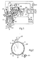
- Fig. 1 shows a schematic view of an electronic injection system for an internal combustion engine 101, conveniently a four-cylinder engine, illustrated partially in cross section.
- the said system comprises an electronic control system 102 comprising, in substantially. known manner, a microprocessor 121 and memories in which are memorised maps relative to various operating conditions of engine 101.
- the said control system 102 also comprises a counter 122, an updatable memory register 123, and an addressable- cell memory register 124 the operation of which is described later on.
- the said control system 102 receives signals from:
- the said electronic control system 102 is connected to an electrical supply battery 115 and grounded, and, depending on the signals received from the aforementioned sensors, engine speed and air density are employed for determining fuel supply according to the required mixture strength.
- the said control system 102 therefore controls the opening time of electroinjectors 116 located inside manifold 107 next to the intake valve of each respective cylinder, so as to control the amount of fuel supplied to the various cylinders on engine 101, and also controls injection timing for commencing fuel supply according to the strokes (induction, compression, expansion, exhaust) of engine 101.
- the said electroinjector 116 is supplied with fuel via a pressure regulator 117 sensitive to the pressure inside induction manifold 107 and having a fuel intake pipe 118 from a pump (not shown) and a return pipe 119 to a tank (not shown).
- Electronic control system 102 is also connected to an ignition pulse control unit 120.
- pulley 104 presents four projecting teeth 31 equally spaced at 90° intervals, sensor 103 being arranged facing the passage of the said teeth 31 and at such an angle as to detect passage of the same at +10° and +100° respectively in relation to the top dead centre of each cylinder.
- the sequence of signals (S) supplied by the said sensor 103 during rotation of drive shaft 125 is shown in Fig. 5a. Also as shown in Fig.
- sensor 105 is arranged facing a disc 32 secured angularly to the shaft of distributor 126 and having two projecting teeth 33 spaced 90° apart.
- the said sensor 105 is located in the distributor portion relative to cylinder 3 and at such an angle that, when a tooth 31 is arranged facing speed sensor 103, the first tooth 33 on disc 32 lags by 27.5° in relation to the axis of sensor 105.
- Fig. 5b shows the sequence of signals (C) supplied by sensor 105, which, for each complete cycle of engine 101, presents a first signal lagging by 55° in relation to the foregoing signal from sensor 103, and, in the example shown, leading by 135° in relation to the top dead centre of cylinder 3 (indicated by P 3 in Fig.
- Fig. 5d shows, one on top of the other for cylinders 4, 2, 1 and 3 respectively, the stroke sequence of each cylinder as related to the angle sequence of the signals from sensor 103 shown in Fig. 5a.
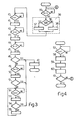
- the letters I, C, E or Ex in each box indicate the induction, compression, expansion or exhaust stroke respectively of each cylinder. Operation of the system for stroke identification of engine 101, according to the present invention, will now be described with reference to Fig. 3.
- microprocessor 121 Via block 35, microprocessor 121 detects an incoming signal from sensor 103 or 105 (Fig. 5a or 5b respectively). Upon reception of one of the said signals, block 35 goes on to block 36 which determines whether the incoming signal is from sensor 105.
- block 36 goes on to block 37 which shifts one place leftwards the figures contained in a memory register, e.g. memory register 123, and enters a 0 in the extreme right-hand position. If the incoming signal is not from sensor 105, block 36 goes on to block 38 which shifts one place leftwards the figures contained in memory register 123 and enters a "1" in the extreme right-hand position.
- Blocks 36, 37 and 38 form part of an overall block 39 (shown by the dotted line in Fig. 3).
- Block 37 or 38 goes on to block 40 which detects a second incoming signal from sensor 103 or 105.
- block 40 goes on to block 41, which operates the same way as block 39, and, from there, to block 42 which detects a further incoming signal (i.e. the third) from sensor 103 or 105.
- block 42 goes on to block 43, which operates the same way as block 39, and, from there, to block 44 which detects a further incoming signal (i.e. the fourth) from sensor 103 or 105.
- block 44 goes on to block 45, which operates the same way as block 39, and, from there, to block 46 which determines whether the sequence of signals received and memorised in memory register 123 matches one of a number of given four-signal sequences.
- each sequence is indicated the content of register 123 and the number, from 0 to 9, to which counter 122 is preset by block 47, which is activated by positive identification by block 46.
- Counter 122 the output sequence of which is shown in Fig. 5c, is moved forward one unit for each incoming signal from sensor 103 or 105, and has a maximum capacity ranging from 0 to 9.
- the maximum count (9) is reached, the next signal from sensor 103 sends the counter, and also memory register 123, back to 0, in that the same signal cycle from sensors 103 and 105 and the same stroke cycle of engine 101 are repeated continually.
- the output from 0 to 9 of counter 122 thus indicates the strokes of engine 101, by informing the output switch, as shown in Fig. 5, of the intermediate or final status of each specific stroke of each cylinder.
- microprocessor 121 receiving the output of counter 122 assigns, to each said output value, one of the numbers shown in Fig. 5d relative to the various cylinders on engine 101 and indicating the stroke status of the same.
- microprocessor 121 assigns a 3 to cylinder 4, a 1 to cylinder 2, a 7 to cylinder 1 and a 5 to cylinder 3, thus indicating that the said four cylinders are at the end of the expansion, compression, induction and exhaust stroke respectively.
- fuel supply to injectors 116 and ignition by unit 120 are performed at the required cylinder strokes, when the said numbers from 0 to 7 indicating the specific stroke status of each cylinder are supplied.
- block 46 goes on to block 49, which detects the next incoming signal from sensor 103 or 105, and, from there, to block 50 which operates the same way as block 39.
- Block 50 then goes on to block 51 which, like block 46, detects the sequence of the last four signals received from sensors 103 and 105, the first signal detected by block 35 being discarded, and, if the said sequence matches one of those memorised and listed in Table 1, activates block 47, in the same way as block 46, so as to preset the output of counter 122 to the figure shown in Table 1 beside each identified sequence.
- block 51 goes on to block 52 which detects reception of a further signal from sensor 103 or 105. If such is received, block 52 goes on to block 53 which, operating in the same way as block 39, goes on to block 54, which determines whether or not the incoming sequence matches one of the set four-signal sequences from sensors 103 and 105 listed in Table 1, or a sequence of six consecutive signals from sensor 103, which corresponds to counter 122 being preset to output 0, as shown in Table 2.
- block 54 Upon identification by block 54 of one of the Table 1 sequences or the Table 2 sequence, block 54 goes on to block 47. In the case of negative identification, block 54 goes on to block 55 which discards, from the sequence of signals memorised in register 123, the first signal detected by block 35, after which, it goes on to block 52 for detecting a further signal from sensor 103 or 105.
- the type of sequence identified and, therefore, the time required for stroke identification of engine 101 depend on the starting angle of the engine.
- the first signal detected by block 35 (Fig. 3) is an S signal from sensor 103, whereas those detected by blocks 40, 42 and 44 are S, C and S signals.
- block 46 does not identify the SSCS sequence, neither is the SCSS sequence identified by block 51, and only by block 54 is the CSSS sequence identified, corresponding to counter 122 being preset to output 7 as shown in Fig. 5.
- identification commences after tooth 31 has moved past sensor 103 (angle R 2 )
- identification is performed by block 51 which detects the CSSS sequence and also, via block 47, causes counter 122 to be preset to output 7. If, on the other hand identification commences from angle R 3 , identification is performed by block 46 detecting the memorised CSSS sequence.
- identification is performed by block 54 which detects the memorised sequence of six S signals and, via block 47, causes counter 122 to be preset to output 0.
- blocks 35, 40, 42 and 44 detect the SSSS sequence, which is not identified by block 46 or even by block 51 with the addition of a further S signal detected by block 49, whereas block 54 identifies the SSSC sequence which, via block 47, presets counter 122 to output 1.
- the same SSSC sequence is identified by block 51 or 46, depending on whether identification commences from angle R 6 or R 7 respectively, and the same block 47 activated for presetting counter 122 to output 1.
- blocks 35, 40, 42 and 44 detect an SSCS signal sequence not identified by block 46, and blocks 49 and 52 cause further S and C signals to be detected until the sequence of the last four signals (CSSC) is identified by block 54 which, via block 47, causes counter 122 to be preset to output 4.
- the said preset output 4 is controlled by block 51 or 46, which detect the same last-four-signal sequence (CSSC) starting from identification angles Rg or R 10 respectively.
- counter 122 the output of which is increased one unit for each incoming signal from sensor 103 or 105, and to which microprocessor 121 may assign the respective numbers listed vertically in Fig. 5d and relative to the specific stroke condition of each cylinder, provides for performing each specific memorised routine controlling supply to injectors 116 and ignition by unit 120.
- microprocessor 121 In normal operating mode subsequent to stroke identification, microprocessor 121 also checks the accuracy of the sequence of signals received from sensors 103 and 105. As shown in Fig. 4, microprocessor 121 goes on to a block 57 for detecting reception of each incoming signal from sensor 103 or 105. When an incoming signal is received, block 57 goes on to block 58 which increases the output of counter 122 by one unit and goes on to block 59 which, like block 39 in Fig. 3, shifts the previous figures leftwards and enters, in the least significant right-hand position of memory register 123, a 0 or a 1, depending on whether the signal detected by block 57 is from sensor 105 or 103.
- Block 59 then goes on to block 60 which compares the content of the said updatable register 123 with that of memory register 124, in the cell addressed by the current output of counter 122.
- the said register 124 has ten cells addressed by numbers 0 to 9 and in which are memorised the same signal sequences storable in memory register 123 subsequent to progressive reception of the signals from sensors 103 and 105. Table 3 below shows the memorised content relative to each cell number:
- Block 47 in Fig. 3 in addition to presetting the output of counter 122 as described, also presets the content of memory register 123 to the sequence shown in Table 3.
- Block 60 then goes on to block 61 which, in the case of a positive match between the content of register 123 and the specific cell in register 124, enables continued performance of the routines on microprocessor 121.
- block 61 goes back to block 35 in Fig. 3 for further stroke identification of engine 101.
- the internal combustion engine stroke identification system provides for using only one sensor 105 cooperating with disc 32 secured to the shaft of distributor 126, which, in turn, provides for low- cost manufacture and assembly, eliminating interference and fase signalling between pairs of sensors, and, more importantly, for considerably reducing identification time, even with only one sensor 105, such identification time never exceeding the reception of six consecutive signals from sensor. 103 or 105, regardless of the starting angle of the drive shaft on engine 101.
Landscapes
- Engineering & Computer Science (AREA)
- Chemical & Material Sciences (AREA)
- Combustion & Propulsion (AREA)
- Mechanical Engineering (AREA)
- General Engineering & Computer Science (AREA)
- Physics & Mathematics (AREA)
- Electromagnetism (AREA)
- Combined Controls Of Internal Combustion Engines (AREA)
Description
- The present invention relates to an internal combustion engine stroke identification system, particularly for application on a sequential, timed electronic injection system.
- Electronic injection systems on internal combustion engines are known to present an electronic control system which, depending on the signals received from various sensors (mainly engine speed/stroke and intake air pressure/temperature sensors), determines, for example, air density inside the manifold and engine speed, and calculates, via interpolation on respective memorised maps, the stroke and timing for injecting fuel into the injectors, as well as the spark lead. Provision may be made for one injector per cylinder, located downstream from the throttle valve, or for a single injector located up- or downstream from the throttle valve. Such a sequential, timed electronic injection system therefore employs a given number of angular references on the drive and distributor shafts, for enabling the control system to determine the stroke (induction, compression, expansion, exhaust) of each cylinder. Each half revolution of the engine, the control system is therefore able to open the specific injector relative to the cylinder performing the required stroke. The engine strokes, however, must be identified by the control system within the shortest possible time after starting, for enabling correct fuel supply as soon as the engine is started up.
- Use is generally made of a first sensor facing a pulley angularly integral with the drive shaft, the said pulley having four projecting teeth equally spaced at 90° intervals, and a pair of sensors facing a cam secured angularly to the distributor shaft, which cam presents a pair of teeth spaced 90° apart. The said pair of sensors, however, presents a number of drawbacks, due to possible interference between the respective magnetic circuits, particularly if the system is fitted onto existing distributors not specifically designed for the purpose, thus resulting in interference signals and false signalling of the said sensors.
- It is also disclosed in US-A-4,365,602 a single sensor detecting signals from the crank shaft and a single sensor detecting signals from a camshaft for cylinder identification, said camshaft includes a single signal producing portion, producing with its two end portions spaced 180° apart signals.
- The aim of the present invention is to provide an improved internal combustion engine stroke identification system designed to overcome the aforementioned drawbacks, i.e. a system providing for substantially eliminating any possibility of false signalling, for lower production cost combined with greater reliability, and for minimising stroke identification time.
- With this aim in view, according to the present invention, there is provided a system identifying the strokes on an internal combustion engine, said system comprising first sensor means detecting four equally spaced angles of a drive shaft, second sensor means detecting given angles of a distributor shaft, and third processing means receiving signals from the said first and said second sensor means, and identifying the strokes on the said engine, characterised by the fact that the said second sensor means comprise a single sensor element positioned for detecting subsequent passage of two portions of an element secured to the said distributor shaft, the said two portions being spaced 90° apart, and the said sensor element being positioned so as to generate the respective signal substantially in the centre portion of interval between signals from the said first sensor means.
- One embodiment of the present invention will now be described, by way of a non-limiting example, with reference to the accompanying drawings, in which:
- Fig. 1 shows a schematic view of an electronic injection system for an internal combustion engine, with the engine stroke identification system according to the present invention;
- Fig. 2 shows a schematic view of a number of component elements on the Fig. 1 system;
- Figs. 3 and 4 show operating block diagrams of the identification system according to the present invention;
- Fig. 5 shows a schematic diagram of a number of signals on the identification system according to the present invention.
- Fig. 1 shows a schematic view of an electronic injection system for an
internal combustion engine 101, conveniently a four-cylinder engine, illustrated partially in cross section. The said system comprises anelectronic control system 102 comprising, in substantially. known manner, amicroprocessor 121 and memories in which are memorised maps relative to various operating conditions ofengine 101. The saidcontrol system 102 also comprises acounter 122, anupdatable memory register 123, and an addressable-cell memory register 124 the operation of which is described later on. The saidcontrol system 102 receives signals from: - a
sensor 103 for detecting the speed ofengine 101 and located opposite apulley 104 ondrive shaft 125; - a
sensor 105 for detecting the stroke ofengine 101 and located inside adistributor 126 as detailed later on; - a
sensor 106 for detecting the absolute pressure insideinduction manifold 107 anengine 101; - a
sensor 108 for detecting the air temperature insidemanifold 107; - a
sensor 110 for detecting the water temperature inside the cooling jacket onengine 101; - a
sensor 111, substantially consisting of a potentiometer, for detecting the setting of athrottle valve 112 located insideinduction manifold 107 and controlled byaccelerator pedal 113; parallel with the saidthrottle valve 112, there is provided an additional air intake valve 114. - The said
electronic control system 102 is connected to anelectrical supply battery 115 and grounded, and, depending on the signals received from the aforementioned sensors, engine speed and air density are employed for determining fuel supply according to the required mixture strength. The saidcontrol system 102 therefore controls the opening time ofelectroinjectors 116 located insidemanifold 107 next to the intake valve of each respective cylinder, so as to control the amount of fuel supplied to the various cylinders onengine 101, and also controls injection timing for commencing fuel supply according to the strokes (induction, compression, expansion, exhaust) ofengine 101. The saidelectroinjector 116 is supplied with fuel via apressure regulator 117 sensitive to the pressure insideinduction manifold 107 and having afuel intake pipe 118 from a pump (not shown) and areturn pipe 119 to a tank (not shown).Electronic control system 102 is also connected to an ignitionpulse control unit 120. As shown in Fig. 2,pulley 104 presents fourprojecting teeth 31 equally spaced at 90° intervals,sensor 103 being arranged facing the passage of the saidteeth 31 and at such an angle as to detect passage of the same at +10° and +100° respectively in relation to the top dead centre of each cylinder. The sequence of signals (S) supplied by thesaid sensor 103 during rotation ofdrive shaft 125 is shown in Fig. 5a. Also as shown in Fig. 2,sensor 105 is arranged facing adisc 32 secured angularly to the shaft ofdistributor 126 and having two projectingteeth 33 spaced 90° apart. In more detail, thesaid sensor 105 is located in the distributor portion relative tocylinder 3 and at such an angle that, when atooth 31 is arranged facingspeed sensor 103, thefirst tooth 33 ondisc 32 lags by 27.5° in relation to the axis ofsensor 105. Fig. 5b shows the sequence of signals (C) supplied bysensor 105, which, for each complete cycle ofengine 101, presents a first signal lagging by 55° in relation to the foregoing signal fromsensor 103, and, in the example shown, leading by 135° in relation to the top dead centre of cylinder 3 (indicated by P3 in Fig. 5d in which Pi, P4 and P2 indicate the top dead centres of theother cylinders sensor 105, when thesecond tooth 33 passes in front of it, leads by 135° in relation to the top dead centre (P 4) ofcylinder 4, and lags by 180° in relation to the first signal fromsensor 105, by virtue of each full turn ofdisc 32 corresponding to two turns ofdrive shaft 125 and, consequently, ofpulley 104. - Fig. 5d shows, one on top of the other for
cylinders sensor 103 shown in Fig. 5a. The letters I, C, E or Ex in each box indicate the induction, compression, expansion or exhaust stroke respectively of each cylinder. Operation of the system for stroke identification ofengine 101, according to the present invention, will now be described with reference to Fig. 3. Viablock 35,microprocessor 121 detects an incoming signal fromsensor 103 or 105 (Fig. 5a or 5b respectively). Upon reception of one of the said signals,block 35 goes on toblock 36 which determines whether the incoming signal is fromsensor 105. If it is,block 36 goes on to block 37 which shifts one place leftwards the figures contained in a memory register,e.g. memory register 123, and enters a 0 in the extreme right-hand position. If the incoming signal is not fromsensor 105,block 36 goes on toblock 38 which shifts one place leftwards the figures contained inmemory register 123 and enters a "1" in the extreme right-hand position.Blocks Block 37 or 38 goes on to block 40 which detects a second incoming signal fromsensor block 40 goes on toblock 41, which operates the same way asblock 39, and, from there, toblock 42 which detects a further incoming signal (i.e. the third) fromsensor block 42 goes on toblock 43, which operates the same way asblock 39, and, from there, toblock 44 which detects a further incoming signal (i.e. the fourth) fromsensor block 44 goes on toblock 45, which operates the same way asblock 39, and, from there, toblock 46 which determines whether the sequence of signals received and memorised inmemory register 123 matches one of a number of given four-signal sequences. The said sequences are listed in the following Table 1, in which the letter S indicates the signals fromsensor 103, and C the signals fromsensor 105. Beside each sequence is indicated the content ofregister 123 and the number, from 0 to 9, to whichcounter 122 is preset by block 47, which is activated by positive identification byblock 46.Counter 122, the output sequence of which is shown in Fig. 5c, is moved forward one unit for each incoming signal fromsensor sensor 103 sends the counter, and alsomemory register 123, back to 0, in that the same signal cycle fromsensors engine 101 are repeated continually. The output from 0 to 9 ofcounter 122 thus indicates the strokes ofengine 101, by informing the output switch, as shown in Fig. 5, of the intermediate or final status of each specific stroke of each cylinder. For example, when the output ofcounter 122 switches to 7, this means the cylinders onengine 101 are roughly halfway through: expansion (cylinder 4), compression (cylinder 2), induction (cylinder 1) and exhaust (cylinder 3). In more detail,microprocessor 121 receiving the output ofcounter 122 assigns, to each said output value, one of the numbers shown in Fig. 5d relative to the various cylinders onengine 101 and indicating the stroke status of the same. For example, with an output of 8 oncounter 122,microprocessor 121 assigns a 3 tocylinder 4, a 1 tocylinder 2, a 7 tocylinder 1 and a 5 tocylinder 3, thus indicating that the said four cylinders are at the end of the expansion, compression, induction and exhaust stroke respectively. In like manner, fuel supply toinjectors 116 and ignition byunit 120, as determined by respective maps stored incontrol unit 102, are performed at the required cylinder strokes, when the said numbers from 0 to 7 indicating the specific stroke status of each cylinder are supplied. -

- If none of the said memorised sequences of signals from
sensors block 46, block 46 goes on to block 49, which detects the next incoming signal fromsensor block 39.Block 50 then goes on to block 51 which, likeblock 46, detects the sequence of the last four signals received fromsensors block 35 being discarded, and, if the said sequence matches one of those memorised and listed in Table 1, activates block 47, in the same way asblock 46, so as to preset the output ofcounter 122 to the figure shown in Table 1 beside each identified sequence. In the case of negative identification byblock 51, block 51 goes on to block 52 which detects reception of a further signal fromsensor block 39, goes on to block 54, which determines whether or not the incoming sequence matches one of the set four-signal sequences fromsensors sensor 103, which corresponds to counter 122 being preset tooutput 0, as shown in Table 2.
- Upon identification by block 54 of one of the Table 1 sequences or the Table 2 sequence, block 54 goes on to block 47. In the case of negative identification, block 54 goes on to block 55 which discards, from the sequence of signals memorised in
register 123, the first signal detected byblock 35, after which, it goes on to block 52 for detecting a further signal fromsensor - The type of sequence identified and, therefore, the time required for stroke identification of
engine 101 depend on the starting angle of the engine. As shown in Fig. 5e, in the case of identification commencing after thefirst tooth 33 moves past sensor 105 (angle R1), the first signal detected by block 35 (Fig. 3) is an S signal fromsensor 103, whereas those detected byblocks block 46 does not identify the SSCS sequence, neither is the SCSS sequence identified byblock 51, and only by block 54 is the CSSS sequence identified, corresponding to counter 122 being preset tooutput 7 as shown in Fig. 5. If, on the other hand, identification commences aftertooth 31 has moved past sensor 103 (angle R2), identification is performed byblock 51 which detects the CSSS sequence and also, via block 47, causes counter 122 to be preset tooutput 7. If, on the other hand identification commences from angle R3, identification is performed byblock 46 detecting the memorised CSSS sequence. - As shown in Fig. 5f, if identification commences from angle R4, identification is performed by block 54 which detects the memorised sequence of six S signals and, via block 47, causes counter 122 to be preset to
output 0. - As shown in Fig. 5g, if identification commences from angle Rs, blocks 35, 40, 42 and 44 detect the SSSS sequence, which is not identified by
block 46 or even byblock 51 with the addition of a further S signal detected byblock 49, whereas block 54 identifies the SSSC sequence which, via block 47, presets counter 122 tooutput 1. The same SSSC sequence is identified byblock output 1. - As shown in Fig. 5h, if identification commences from angle Rs, blocks 35, 40, 42 and 44 detect an SSCS signal sequence not identified by
block 46, and blocks 49 and 52 cause further S and C signals to be detected until the sequence of the last four signals (CSSC) is identified by block 54 which, via block 47, causes counter 122 to be preset tooutput 4. The saidpreset output 4 is controlled byblock - Subsequent to stroke identification of
engine 101, counter 122, the output of which is increased one unit for each incoming signal fromsensor microprocessor 121 may assign the respective numbers listed vertically in Fig. 5d and relative to the specific stroke condition of each cylinder, provides for performing each specific memorised routine controlling supply toinjectors 116 and ignition byunit 120. - In normal operating mode subsequent to stroke identification,
microprocessor 121 also checks the accuracy of the sequence of signals received fromsensors microprocessor 121 goes on to ablock 57 for detecting reception of each incoming signal fromsensor counter 122 by one unit and goes on to block 59 which, likeblock 39 in Fig. 3, shifts the previous figures leftwards and enters, in the least significant right-hand position ofmemory register 123, a 0 or a 1, depending on whether the signal detected byblock 57 is fromsensor Block 59 then goes on to block 60 which compares the content of the saidupdatable register 123 with that ofmemory register 124, in the cell addressed by the current output ofcounter 122. The saidregister 124 has ten cells addressed bynumbers 0 to 9 and in which are memorised the same signal sequences storable inmemory register 123 subsequent to progressive reception of the signals fromsensors -

counter 122 as described, also presets the content ofmemory register 123 to the sequence shown in Table 3.Block 60 then goes on to block 61 which, in the case of a positive match between the content ofregister 123 and the specific cell inregister 124, enables continued performance of the routines onmicroprocessor 121. In the case of a negative match, however, indicating an incorrect signal sequence fromcontrol unit 102, block 61 goes back to block 35 in Fig. 3 for further stroke identification ofengine 101. - The advantages of the internal combustion engine stroke identification system according to the present invention will be clear from the foregoing description. In particular, it provides for using only one
sensor 105 cooperating withdisc 32 secured to the shaft ofdistributor 126, which, in turn, provides for low- cost manufacture and assembly, eliminating interference and fase signalling between pairs of sensors, and, more importantly, for considerably reducing identification time, even with only onesensor 105, such identification time never exceeding the reception of six consecutive signals from sensor. 103 or 105, regardless of the starting angle of the drive shaft onengine 101.
Claims (8)
Applications Claiming Priority (2)
| Application Number | Priority Date | Filing Date | Title |
|---|---|---|---|
| IT67512/85A IT1184958B (en) | 1985-06-04 | 1985-06-04 | IDENTIFICATION SYSTEM OF THE PHASES OF AN ENDUTERMIC ENGINE |
| IT6751285 | 1985-06-04 |
Publications (3)
| Publication Number | Publication Date |
|---|---|
| EP0204221A2 EP0204221A2 (en) | 1986-12-10 |
| EP0204221A3 EP0204221A3 (en) | 1988-07-13 |
| EP0204221B1 true EP0204221B1 (en) | 1990-12-12 |
Family
ID=11303039
Family Applications (1)
| Application Number | Title | Priority Date | Filing Date |
|---|---|---|---|
| EP86106960A Expired - Lifetime EP0204221B1 (en) | 1985-06-04 | 1986-05-22 | Combustion engine stroke identification system |
Country Status (6)
| Country | Link |
|---|---|
| US (1) | US4765306A (en) |
| EP (1) | EP0204221B1 (en) |
| BR (1) | BR8602903A (en) |
| DE (1) | DE3676114D1 (en) |
| ES (1) | ES8703965A1 (en) |
| IT (1) | IT1184958B (en) |
Families Citing this family (16)
| Publication number | Priority date | Publication date | Assignee | Title |
|---|---|---|---|---|
| IT1184957B (en) * | 1985-06-04 | 1987-10-28 | Weber Spa | FUEL SUPPLY SYSTEM AT THE START OF AN ENDOTHERMAL ENGINE INCLUDING AN ELECTRONIC INJECTION SYSTEM |
| JP2541949B2 (en) * | 1986-11-28 | 1996-10-09 | 本田技研工業株式会社 | Ignition timing control device for 4-cycle internal combustion engine |
| US4856489A (en) * | 1987-06-08 | 1989-08-15 | Mitsubishi Denki Kabushiki Kaisha | Ignition timing control apparatus for an internal combustion engine |
| JPH0174376U (en) * | 1987-11-09 | 1989-05-19 | ||
| JP2648928B2 (en) * | 1988-04-28 | 1997-09-03 | 富士重工業株式会社 | Cylinder discriminating apparatus and control method for each cylinder of automobile engine |
| FR2637652B1 (en) * | 1988-10-11 | 1993-12-31 | Bendix Electronics Sa | DEVICE FOR MARKING AN OPERATING CYCLE OF AN INTERNAL COMBUSTION ENGINE |
| DE4002228C2 (en) * | 1990-01-26 | 1995-07-27 | Bosch Gmbh Robert | Process for recognizing the working stroke in a four-stroke engine |
| IT1239869B (en) * | 1990-01-26 | 1993-11-15 | Weber Srl | PERFECTED TYPE SYSTEM FOR IDENTIFYING THE PHASES OF AN ENDOTHERMAL ENGINE |
| IT1239867B (en) * | 1990-01-26 | 1993-11-15 | Weber Srl | IDENTIFICATION SYSTEM OF THE PHASES OF AN ENDOTHERMAL ENGINE |
| DE4141713C2 (en) * | 1991-12-18 | 2003-11-06 | Bosch Gmbh Robert | Encoder arrangement for cylinder detection and emergency operation in an internal combustion engine with n cylinders |
| DE19929291A1 (en) * | 1999-06-25 | 2000-12-28 | Volkswagen Ag | Four-stroke internal combustion engine with semi-sequential fuel injection has reference marks evenly distributed in groups of at least two per group to rotate synchronism with camshaft |
| US6640777B2 (en) * | 2000-10-12 | 2003-11-04 | Kabushiki Kaisha Moric | Method and device for controlling fuel injection in internal combustion engine |
| JP4270534B2 (en) | 2000-10-12 | 2009-06-03 | ヤマハモーターエレクトロニクス株式会社 | Internal combustion engine load detection method, control method, ignition timing control method, and ignition timing control device |
| US6742502B2 (en) | 2000-10-12 | 2004-06-01 | Kabushiki Kaisha Moric | Engine control method and apparatus |
| JP4061951B2 (en) | 2001-05-16 | 2008-03-19 | 国産電機株式会社 | 4-stroke internal combustion engine stroke determination method and apparatus |
| JP4825786B2 (en) * | 2007-12-20 | 2011-11-30 | 本田技研工業株式会社 | 4-cycle engine stroke discrimination device |
Family Cites Families (9)
| Publication number | Priority date | Publication date | Assignee | Title |
|---|---|---|---|---|
| DE2951622A1 (en) * | 1979-12-21 | 1981-07-02 | Volkswagenwerk Ag, 3180 Wolfsburg | ARRANGEMENT FOR OBTAINING SIGNALS FOR IGNITION AND / OR FUEL INJECTION FOR A 4-STROKE COMBUSTION ENGINE |
| US4338903A (en) * | 1980-09-02 | 1982-07-13 | Motorola Inc. | Electronic cylinder identification apparatus for synchronizing fuel injection |
| JPS5759058A (en) * | 1980-09-25 | 1982-04-09 | Toyota Motor Corp | Ignition timing control method of internal combustion engine |
| DE3100825A1 (en) * | 1981-01-14 | 1982-08-12 | Robert Bosch Gmbh, 7000 Stuttgart | DEVICE FOR CONTROLLING THE IGNITION AND / OR FUEL INJECTION AND / OR GEAR SHIFTING PROCESSES IN INTERNAL COMBUSTION ENGINES |
| JPS57203825A (en) * | 1981-06-10 | 1982-12-14 | Honda Motor Co Ltd | Controlling device for electronic fuel injection of multi cylinder internal-combustion engine |
| US4494509A (en) * | 1982-10-22 | 1985-01-22 | Electromotive, Inc. | High resolution electronic ignition control system |
| US4553427A (en) * | 1983-03-08 | 1985-11-19 | Nippondenso Co., Ltd. | Rotational reference position detection apparatus |
| JPS60119345A (en) * | 1983-12-01 | 1985-06-26 | Nippon Soken Inc | Control method of internal-combustion engine |
| JPS6187971A (en) * | 1984-10-06 | 1986-05-06 | Honda Motor Co Ltd | Ignition system for internal combustion engines |
-
1985
- 1985-06-04 IT IT67512/85A patent/IT1184958B/en active
-
1986
- 1986-05-22 EP EP86106960A patent/EP0204221B1/en not_active Expired - Lifetime
- 1986-05-22 DE DE8686106960T patent/DE3676114D1/en not_active Expired - Lifetime
- 1986-06-04 ES ES555713A patent/ES8703965A1/en not_active Expired
- 1986-06-04 US US06/870,454 patent/US4765306A/en not_active Expired - Fee Related
- 1986-06-04 BR BR8602903A patent/BR8602903A/en not_active IP Right Cessation
Also Published As
| Publication number | Publication date |
|---|---|
| IT8567512A0 (en) | 1985-06-04 |
| ES555713A0 (en) | 1987-03-01 |
| EP0204221A3 (en) | 1988-07-13 |
| DE3676114D1 (en) | 1991-01-24 |
| IT1184958B (en) | 1987-10-28 |
| BR8602903A (en) | 1987-03-17 |
| ES8703965A1 (en) | 1987-03-01 |
| EP0204221A2 (en) | 1986-12-10 |
| US4765306A (en) | 1988-08-23 |
| IT8567512A1 (en) | 1986-12-04 |
Similar Documents
| Publication | Publication Date | Title |
|---|---|---|
| US4765306A (en) | Combustion engine stroke identification system | |
| US4998522A (en) | Method for injecting fuel into an internal-combustion engine | |
| US5548995A (en) | Method and apparatus for detecting the angular position of a variable position camshaft | |
| USRE32286E (en) | Apparatus for electronically controlling internal combustion engine | |
| US4366794A (en) | Fuel injection control method for internal combustion engines | |
| EP1541845B1 (en) | Engine control device | |
| US5021960A (en) | Combustion fault detection apparatus and control system for internal combustion engine | |
| EP0058562B1 (en) | Fuel injection timing signal and crank angle signal generating apparatus | |
| US4553427A (en) | Rotational reference position detection apparatus | |
| GB2217852A (en) | Cylinder discriminating system for an automotive engine | |
| US4788956A (en) | Method of detecting abnormality in crank angle signal of internal combustion engines | |
| US4616617A (en) | Method and arrangement for combustion chamber identification in an internal combustion engine | |
| US4732122A (en) | Starting fuel supply system for an internal combustion engine, comprising an electronic injection system | |
| US4959996A (en) | Control signal generator for an internal combustion engine | |
| US6098604A (en) | Cylinder identifying device for internal combustion engines | |
| US4844039A (en) | Fuel supply control system for internal combustion engines | |
| US4725954A (en) | Apparatus and method for controlling fuel supply to internal combustion engine | |
| US4955348A (en) | Fuel injection conversion system for V-twin motorcycle engines | |
| US4586479A (en) | Electronic fuel injection control with variable injection intervals | |
| EP0208183B1 (en) | System for limiting the maximum speed of an internal combustion engine comprising an electronic injection system | |
| EP0115827B1 (en) | Method of controlling engine | |
| EP1439299A1 (en) | Engine control device | |
| EP0176359A2 (en) | Fuel supply control method for multicylinder internal combustion engines during occurrence of abnormality in engine rotational angle position sensing means | |
| EP0684376A1 (en) | Electronic system for identifying the strokes of an internal combustion engine | |
| EP0072162B2 (en) | Method and system for controlling ignition timing in a multicylinder internal combustion engine |
Legal Events
| Date | Code | Title | Description |
|---|---|---|---|
| PUAI | Public reference made under article 153(3) epc to a published international application that has entered the european phase |
Free format text: ORIGINAL CODE: 0009012 |
|
| AK | Designated contracting states |
Kind code of ref document: A2 Designated state(s): DE FR GB NL SE |
|
| PUAL | Search report despatched |
Free format text: ORIGINAL CODE: 0009013 |
|
| AK | Designated contracting states |
Kind code of ref document: A3 Designated state(s): DE FR GB NL SE |
|
| RAP1 | Party data changed (applicant data changed or rights of an application transferred) |
Owner name: WEBER S.R.L. |
|
| 17P | Request for examination filed |
Effective date: 19881223 |
|
| 17Q | First examination report despatched |
Effective date: 19890823 |
|
| GRAA | (expected) grant |
Free format text: ORIGINAL CODE: 0009210 |
|
| AK | Designated contracting states |
Kind code of ref document: B1 Designated state(s): DE FR GB NL SE |
|
| ET | Fr: translation filed | ||
| REF | Corresponds to: |
Ref document number: 3676114 Country of ref document: DE Date of ref document: 19910124 |
|
| PGFP | Annual fee paid to national office [announced via postgrant information from national office to epo] |
Ref country code: SE Payment date: 19910424 Year of fee payment: 6 |
|
| PGFP | Annual fee paid to national office [announced via postgrant information from national office to epo] |
Ref country code: NL Payment date: 19910531 Year of fee payment: 6 |
|
| PLBE | No opposition filed within time limit |
Free format text: ORIGINAL CODE: 0009261 |
|
| STAA | Information on the status of an ep patent application or granted ep patent |
Free format text: STATUS: NO OPPOSITION FILED WITHIN TIME LIMIT |
|
| 26N | No opposition filed | ||
| PG25 | Lapsed in a contracting state [announced via postgrant information from national office to epo] |
Ref country code: SE Effective date: 19920523 |
|
| PG25 | Lapsed in a contracting state [announced via postgrant information from national office to epo] |
Ref country code: NL Effective date: 19921201 |
|
| NLV4 | Nl: lapsed or anulled due to non-payment of the annual fee | ||
| EUG | Se: european patent has lapsed |
Ref document number: 86106960.7 Effective date: 19921204 |
|
| PGFP | Annual fee paid to national office [announced via postgrant information from national office to epo] |
Ref country code: FR Payment date: 20000428 Year of fee payment: 15 |
|
| PGFP | Annual fee paid to national office [announced via postgrant information from national office to epo] |
Ref country code: GB Payment date: 20000517 Year of fee payment: 15 |
|
| PGFP | Annual fee paid to national office [announced via postgrant information from national office to epo] |
Ref country code: DE Payment date: 20000727 Year of fee payment: 15 |
|
| PG25 | Lapsed in a contracting state [announced via postgrant information from national office to epo] |
Ref country code: GB Free format text: LAPSE BECAUSE OF NON-PAYMENT OF DUE FEES Effective date: 20010522 |
|
| GBPC | Gb: european patent ceased through non-payment of renewal fee |
Effective date: 20010522 |
|
| PG25 | Lapsed in a contracting state [announced via postgrant information from national office to epo] |
Ref country code: FR Free format text: LAPSE BECAUSE OF NON-PAYMENT OF DUE FEES Effective date: 20020131 |
|
| PG25 | Lapsed in a contracting state [announced via postgrant information from national office to epo] |
Ref country code: DE Free format text: LAPSE BECAUSE OF NON-PAYMENT OF DUE FEES Effective date: 20020301 |