EP0203713A2 - High flow electrofiltration - Google Patents
High flow electrofiltration Download PDFInfo
- Publication number
- EP0203713A2 EP0203713A2 EP86303109A EP86303109A EP0203713A2 EP 0203713 A2 EP0203713 A2 EP 0203713A2 EP 86303109 A EP86303109 A EP 86303109A EP 86303109 A EP86303109 A EP 86303109A EP 0203713 A2 EP0203713 A2 EP 0203713A2
- Authority
- EP
- European Patent Office
- Prior art keywords
- channel
- feed
- filter device
- product
- slurry
- Prior art date
- Legal status (The legal status is an assumption and is not a legal conclusion. Google has not performed a legal analysis and makes no representation as to the accuracy of the status listed.)
- Withdrawn
Links
Images

Classifications
-
- B—PERFORMING OPERATIONS; TRANSPORTING
- B01—PHYSICAL OR CHEMICAL PROCESSES OR APPARATUS IN GENERAL
- B01D—SEPARATION
- B01D57/00—Separation, other than separation of solids, not fully covered by a single other group or subclass, e.g. B03C
- B01D57/02—Separation, other than separation of solids, not fully covered by a single other group or subclass, e.g. B03C by electrophoresis
-
- B—PERFORMING OPERATIONS; TRANSPORTING
- B01—PHYSICAL OR CHEMICAL PROCESSES OR APPARATUS IN GENERAL
- B01D—SEPARATION
- B01D29/00—Filters with filtering elements stationary during filtration, e.g. pressure or suction filters, not covered by groups B01D24/00 - B01D27/00; Filtering elements therefor
- B01D29/39—Filters with filtering elements stationary during filtration, e.g. pressure or suction filters, not covered by groups B01D24/00 - B01D27/00; Filtering elements therefor with hollow discs side by side on, or around, one or more tubes, e.g. of the leaf type
-
- B—PERFORMING OPERATIONS; TRANSPORTING
- B01—PHYSICAL OR CHEMICAL PROCESSES OR APPARATUS IN GENERAL
- B01D—SEPARATION
- B01D29/00—Filters with filtering elements stationary during filtration, e.g. pressure or suction filters, not covered by groups B01D24/00 - B01D27/00; Filtering elements therefor
- B01D29/88—Filters with filtering elements stationary during filtration, e.g. pressure or suction filters, not covered by groups B01D24/00 - B01D27/00; Filtering elements therefor having feed or discharge devices
- B01D29/94—Filters with filtering elements stationary during filtration, e.g. pressure or suction filters, not covered by groups B01D24/00 - B01D27/00; Filtering elements therefor having feed or discharge devices for discharging the filter cake, e.g. chutes
- B01D29/945—Filters with filtering elements stationary during filtration, e.g. pressure or suction filters, not covered by groups B01D24/00 - B01D27/00; Filtering elements therefor having feed or discharge devices for discharging the filter cake, e.g. chutes for continuously discharging concentrated liquid
-
- B—PERFORMING OPERATIONS; TRANSPORTING
- B01—PHYSICAL OR CHEMICAL PROCESSES OR APPARATUS IN GENERAL
- B01D—SEPARATION
- B01D35/00—Filtering devices having features not specifically covered by groups B01D24/00 - B01D33/00, or for applications not specifically covered by groups B01D24/00 - B01D33/00; Auxiliary devices for filtration; Filter housing constructions
- B01D35/06—Filters making use of electricity or magnetism
Definitions
- Electrically augmented filtration devices and processes are in commercial operation, but those in use have involved immersing anodic and cathodic electrode assemblies in a slurry bath, depositing a cake on certain of the electrode assemblies and thereafter removing the cake, as product, from those assemblies by means such as doctoring or blow-back. Quite often, however, the desired final product is a slurry, rather than relatively dry cake, so that the cake product must be reslurried to the desired moisture content; a retrogressive process step, so to speak. Then too, the commercial process just described has some of the characteristics of a batch-type operation; each of the electrode assemblies on which cake is to be deposited, as stated above, passing through a cycle of immersion, cake deposition, cake doctoring and reimmersion. Such batch-type processes tend to require rather complex and expensive mechanical equipment and frequent maintenance attention.
- hollow electrode assemblies which are normally submerged in the suspension, but bodily removable therefrom for inspection or other purposes.
- These hollow electrode assemblies comprise two types of wall surfaces: ion-pervious walls for electrode assemblies of one polarity and liquid-pervious walls for electrode assemblies of the opposite polarity.
- a source of vacuum is connected to the interior of the electrode assemblies having liquid-pervious walls to provide a controllable pressure differential, thereby producing a flow of carrier liquid through the filtration surfaces, while the solids migrate in the opposite direction, under the influence of the electric field, to deposit as cake upon the electrode assemblies having ion-pervious walls.
- Filtrate or permeate liquid that is, carrier liquid freed of solids, is withdrawn or pumped from the interior of the liquid-filled hollow electrode structure at a controllable rate.
- cake deposition occurs on the hollow electrode assemblies having ion-pervious surfaces: these electrode assemblies are filled with an electrolyte and have an electrode element therein immersed in the electrolyte. These electrode elements are thus isolated from direct contact with the suspension.
- the electrolyte is specially selected for high conductivity and compatibility with the electrode element. By compatibility is meant the relatively non-corrosive character of the electrolyte under the conditions that ordinarily prevail within the hollow electrode assembly. Since decomposition or evolution products and heat are generated at the electrode element within the hollow ion-pervious assembly, provision is made for a flow of electrolyte into and through the electrode chamber so that foreign products, including gases, and heat are swept out of the chamber and a relatively constant predetermined electrolyte composition is maintained.
- the ion-pervious wall of the electrode assembly in these prior art structures comprises a chemically neutral filter media, ion exchange membrane, solid polymeric electrolyte, permeable porous membrane or structures incorporating combinations thereof, which, if film-like in nature or otherwise requiring support, may be backed by a chemically and electrically neutral grid so that a planar deposition surface is presented to the slurry being treated. Since the cake will form on this deposition surface member during electrofiltration and must be removed by contact with doctoring blades, a friction cage or spacing means may be provided to protect the somewhat fragile surface member from direct contact with the doctoring blades.
- the friction cage comprises a thin, open screenwork of relatively hard material covering the deposition surface member for contacting the doctor blades, while spacing means may comprise strips of plastic materials, such as Delrin acetal resin arranged in a frame-like configuration and of a thickness sufficient to prevent contact between the doctor blade and the deposition surface.
- spacing means may comprise strips of plastic materials, such as Delrin acetal resin arranged in a frame-like configuration and of a thickness sufficient to prevent contact between the doctor blade and the deposition surface.
- the electrode assembly is raised to a position of emergence from the suspension, with the layer of collected solids or cake layer adhering thereto. Since the electrolyte remains within the electrode assembly in the raised position, a vacuum is applied internally of the electrode to reduce the pressure on the deposition surface member and so prevent rupture of the member. When the electrode assembly is immersed in operation, the vacuum applied internally serves to remove gaseous products, such as chlorine, oxygen or carbon dioxide evolved at the electrode element.
- the crossflow electrofiltration device of the present invention comprises an elongated housing having a feed-product channel therein with an inlet for feed at one end thereof and a product outlet at the other end of the channel.
- One wall of the channel is composed of a liquid-pervious filter medium and a second wall of the channel is composed of an ion-pervious surface member.
- the suspension or slurry to be treated passes through the feed-product channel between and in contact with both walls.
- the liquid-pervious filter medium wall separates the feed-product channel from a filtrate chamber or channel and there is an electrode within the filtrate chamber.
- An outlet is provided from the filtrate chamber so that filtrate may be withdrawn.
- the ion-pervious surface member separates the feed-product channel from an electrolyte chamber or channel and there is an electrode within the electrolyte chamber immersed in a protective electrolyte.
- An inlet and an outlet are provided for the electrolyte chamber so that fresh electrolyte may be continuously circulated through this chamber.
- Differential pressure and electroosmotic pumping across the liquid-pervious filter media forces liquid from the flowing suspension through the filter media into the filtrate chamber.
- Differential pressure is achieved by pressurizing the feed-product channel hydraulically, such as with a feed pump, and/or applying vacuum to the filtrate chamber.
- the electric field established between the opposed electrodes also tends to impel the solid particles of the suspension toward the ion-pervious surface member.
- the current density due to the applied field is in the range from 0.1 and 135 amps/ft 2 .
- a thin cake of these solid particles may form on part or all of the ion-pervious surface member, but the thickness of such a cake is limited by the velocity of the suspension passing through the feed-product channel, any excessive buildup of cake being sheared away by the flowing suspension.
- velocities in the range of 1 to 20 ft/sec are sufficient to prevent cake formation on the ion-previous surface.
- cake formation on the ion-previous surface is generally undersirable.
- the suspensions to be dewatered may be slurries of polyvinyl chloride, kaolin, ultrafine coal, alumina, T i 0 21 calcium carbonate, humate, magnesium aluminum hydroxide, or other polymer latexs for example.
- the average particle size of the polyvinyl chloride and kaolin solids will be less than 10 microns while the ultrafine coal solids will be fless than 100 microns.
- FIG. 1 there is schematically illustrated in Fig. 1 the crossflow electrofiltration unit of this invention, including a plurality of elongated electrode assemblies arranged in parallel alignment.
- anode assemblies 11 alternate with cathode assemblies 12 and the anode assemblies are spaced from the cathode assemblies by feed-product channels 13.
- the array of anode assemblies and cathode assemblies may be positioned within a confining structure asuch as the housing indicated at 14 which is provided with a feed inlet 16 and a product outlet 17.
- the direction of flow through the feed-product channel between the spaced electrodes is indicated by arrows 18.
- Anolyte is introduced into the anode assemblies 11 through the inlet conduit 21 and anolyte is withdrawn from the anode assemblies 11 through the outlet conduit 22. Filtrate from the feed stream is drawn through liquid-previous faces or filter media 23 of the cathode assemblies through the filtrate withdrawal conduit 24. Electrical conductors 26 and 27 provide the necessary electrical connection to the anode assemblies 11 and cathode assemblies 12.
- a flow of a feed slurry is established through the feed-product channels 13 and a pressure differential is thereby established across the cathode filter media 23, such that the pressure in the feed-product channels exceeds the pressure within the cathode assemblies.
- the anode assemblies and cathode assemblies are energized by means of the electrical conductors 26 and 27 so that an electric potential is established across the feed-product channels 18.
- the combination of the pressure differential across the cathode filter media 23 and the electric field causes liquid from the feed slurry to pass into the cathode assemblies 12, from which it is removed through the filtrate withdrawal conduits 24.
- the transport mechanism through the cathode filter medium is a combination of pressure driven and electroosmotic driven processes.
- the electrical potential across the feed-product channels 13 causes the solids in the slurry to tend to move toward the anode assemblies 11. Some portion of the solids may deposit on the anode assemblies 11; however, if solids initially deposit, accretion of additional solids is limited by the erosive character of the flow of slurry in channels 13 as it passes over the surface of the anode surface member.
- the cake, if any, on the anode assembly thus reaches an equilibrium thickness, dependent on the electric field strength and the flow velocity of the slurry.
- the anode cake if present, tends to protect the anode surface member from abrasion and may have certain other advantages.
- the aforementioned tendency of the solids in the slurry to move toward the anode assembly has the advantage that little or no cake is deposited on the cathode, thus minimizing or eliminating any "blinding" of the cathode filter media 23, so that a relatively high filtrate flow may be established and maintained.
- both the liquid-pervious surfaces and the ion-pervious surfaces of the electrode assemblies were made of a woven fabric, Dynel.
- An unwoven fabric could also have been used.
- Such surfaces were operative on the cathode assemblies (the liquid-pervious surfaces), but had the characteristic, in that application, that particles in suspension would pass through the relatively "open” fabric material with the filtrate during initial operation of the electrofilter, even though the bulk of suspended solids was attracted to the anode assembly.
- This condition, leading to "cloudy” filtrate would prevail until, after operation for a period of hours or days, a thin cathode cake built up on the fabric surface.
- the cathode cake then prevented the passage of solids and a clear filtrate would result.
- a fabric member is, therefore, quite serviceable for the liquid-pervious surfaces in the prior art electrofilters.
- the fabric surface was also operative at the anode assembly in the prior art electrofiltration apparatus, but had the disadvantage that anolyte was e lectroosmotically pumpe8 from the interior of the anode assembly into the bath of suspended solids through the cake deposited on the anode assembly, contaminating both the filter cake and the bath.
- the fabric surface also permitted some fine solids to pass into the anode assembly, at least until a filter cake was established on the anode assembly.
- a positive barrier to entry of the fine suspended particles into the anode assembly is essential.
- Such positive barriers may be provided by ion exchange membranes or, as explained above, by microporous membranes or anisotropic polymeric membranes. Of these membranes, however, only the ion exchange membrane will prevent back migration or electroosmotic pumping of electrolyte through the membrane into the filter cake, if present, and into the concentrated slurry. Where back migration cannot be tolerated due to product purity considerations, then only an ion exchange membrane can be employed. Where some degree of anolyte migration into the cake or concentrated slurry is tolerable, or even desirable, the other types of membranes may be considered for use.
- a crossflow electrofiltration unit 30 is illustrated in a crossflow filtration system 40 capable of providing the necessary feed slurry and anolyte flows to the electrofiltration unit 30.
- a slurry feed tank 31 has an inlet 32 and a feed outlet conduit 33 with a slurry feed pump 35 therein.
- the feed outlet conduit 33 is connected to the crossflow electrofiltration unit 30, where, for example, it supplies slurry to the feed product channels 13 as shown in Fig. 1.
- the product stream which issues from channels 13 is carried away by the product outlet conduit 36. A portion of the product stream may be returned to the feed tank 31 through product recycle line 37.
- the anolyte circuit for supplying anolyte to the anode assembly members 11 (of Fig.
- anolyte tank 41 having an inlet 42 for fresh anolyte and anolyte outlet conduit 43 which has an anolyte pump 44 therein.
- the anolyte outlet conduit 43 is connected to the anode assemblies 11 in the crossflow electrofiltration unit 30.
- a recycle anolyte conduit 47 is provided for returning anolyte which has passed through the anode assembly members 11 to the anolyte tank 41. A portion of the anolyte recycle may be discarded through line 46 to maintain a constant anolyte conductivity at a fixed volume.
- Electrical conductors 26 and 27 are connected to the crossflow electrofiltration unit 30 for establishing the electrical potential provided across the feed product channels 13.
- the filtrate outlet conduit 48 is provided for conducting away-the liquid which has been removed through the cathode filter media 23 (of Fig. 1).
- the crossflow filter device 60 has an upper housing 61 and a lower housing 62, which are spaced from each other by a resilient sealing gasket 63.
- the upper and lower housings are preferably made of an electrically non-conductive material; for example, fiberglass reinforced polyester, polysulfone, polypropylene.
- the housings may be formed of metal with an electrically non-conductive coating thereon, such as a polymer or ceramic coating layer.
- the sealing gasket 63 and the adjacent surfaces of the upper housing 61 and lower housing 62 define a feed-product channel 68 lying between the upper and lower housings.
- Recessed into the upper housing 61 is an electrolyte channel 69 which extends along feed-product channel 68, but which does not extend the full length of the feed-product channel.
- At one extremity of the electrolyte channel 69 it communicates with an electrolyte inlet 71 which passes through upper housing 61, while at the other extremity of the electrolyte channel 69 it is in communication with the electrolyte outlet 72 which also passes through the upper housing 61.
- An electrode element 79 is positioned in electrolyte channel 69 and may take the form of an expanded metal sheet lying next against the wall of the electrolyte channel.
- a non-conductive spacing element 78 is also positioned in the electrolyte channel 69 and an ion-pervious surface member 77 is positioned over electrolyte channel 69, and situated between the gasket 63 and housing 61.
- the fastening means 64, 94 and 67 thereby secures the ion-pervious surface member 77 between the gasket 63 and the housing 61. It will thus be seen that the ion-pervious surface member 77 separates the electrolyte channel 69 from the feed product channel 68.
- the nonconductive spacer element 78 supports the surface member 77 in position where it lies over the electrolyte channel 69.
- the lower housing 62 of the crossflow electrofiltration unit 60 is somewhat similar in configuration to the upper housing 61 in that it has a filtrate channel 81 which faces and is generally coextensive with the electrolyte channel 69 of the upper housing 61.
- filtrate channel 81 is an electrode element 75, and a non-conductive spacer element 74, just as in the electrolyte channel 69.
- a liquid-pervious filter medium 76 is mounted between the lower housing 62 and the sealing gasket 63 in just the same manner as the ion-pervious surface member 77.
- the fastening means 64, 94 and 67 also functions to secure the filter medium 76 in position, forming one wall of the feed product channel 68.
- a conductive electrode stud 82 extends through upper housing 61 to establish electrical contact with the electrode element 79 while a second electrode stud 83 passes through lower housing 62 to provide electrical connection to electrode element 75.
- a filtrate outlet 91 which passes through the lower housing 52.
- Communicating with the feed-product channel 68 beyond the ends of the filtrate channel 81 and electrolyte channel 69 are a threaded feed inlet member 92 which passes through the lower housing 62 at one extremity of the feed-product channel 68 while a threaded product outlet member 93 communicates with the feed-product channel 68 at the opposite extremity thereof.
- the bore 86 for product outlet 93 has a conically counter-bored upper portion 87 in which conical flange 85 of threaded product outlet member 93 is seated.
- the nut 65 is provided on member 93 so that the outlet member 93 can be drawn down to move flange 85 toward engagement with conical surface 87.
- a similar arrangement is provided at feed inlet 92. Holes are provided in the filter medium 76 to mate with the bores at the feed inlet member 92 and product outlet member 93. The edges of the fabric surrounding the holes in the filter medium 76 are fixed between the conical surface 87 and the conical flange 8S to pravide a seal at that point so that feed slurry cannot intrude beneath the filter medium 76.
- the liquid-pervious filter medium may be a fabric, such as D ynel (a copolymer of vinyl chloride and acrylonitrile), an "open" filter.
- a fabric such as D ynel (a copolymer of vinyl chloride and acrylonitrile), an "open" filter.
- a microporous polymer membrane which will retain particle sizes above 20mm, may be employed.
- an anisotropic polymer ultrafiltration membrane capable of retaining particles in the range from 2 to 20mm may be used.
- a feed is introduced into the inlet feed member 92 and flows through the feed-product channel 68 and a product flow exits the crossflow filtration unit 60 through the product outlet 93.
- an electrolyte is introduced into the electrolyte channel 69 through the electrolyte inlet 71 and passes through the electrolyte channel 69 to exit through the electrolyte outlet 72.
- An electric field is established across the feed-product channel 68 by connecting electrode studs 83 and 82 to an external electrical circuit.
- a pressure differential is established across the membrane 76 by the pumps driving the feed through the feed product channel 68.
- a vacuum source can be connected to filtrate outlet 91 to supplement the differential pressure across membrane 76.
- a liquid component of the feed slurry passes through the filter media 76 into filtrate channel 81 and exits from the crossflow filtration unit 60 through the filtrate outlet 91.
- the filter media 76 As the feed advances through the feed-product channel 68, it becomes progressively richer in the solid components thereof and, consequently, a product issues from product outlet 93 which is substantially enriched in solids content when compared with the feed.
- the crossflow electrofilter used in these tests employed a Dynel fabric as the cathodic surface and a cation exchange membrane as the anodic surface.
- the crossflow electrofilter of the present invention makes available a wider choice of operational conditions and so is more flexible in meeting the requirements of particular applications.
- the velocity required to maintain the anode surface free of cake is a function of both the feed solids and the current density. As solids increase, the velocity required also increases. As higher current densities are used, the required velocity increases.
- the velocities used in Table 1 range from 4.0 ft/sec (for Test 5) to 13 ft/sec (for Test 1).
- the performance of a cross flow electro-ultrafilter was tested using a 30% by weight kaolin HT grade feed obtained from Engelhard Minerals.
- the feed conductivity was 1250 micromhos, the feed pH was 6.5.
- the cross flow velocity of the feed across the membrane was provided by an inlet pressure of 30 psi from a single circulating pump as described in Fig. 2.
- the permeate channel was placed under vacuum to increase the permeate driving pressure.
- the anolyte used was a Na 2 S0 4 solution adjusted to 40,000 micromhos conductivity.
- the anode isolating membrane was a cation ion exchange resin membrane obtained from Sybron Corp.
- the ultrafiltration membrane used was S-10 from Dorr-Oliver.
- the feed slurry is pumped from feed tank 100 through conduit 102 by pump 104 to crossflow electrofiltration cell 106.
- electrofiltration cell 106 the feed slurry passes through parallel channels -between electrode elements 101.
- the crossflow electrofiltration cells 106, 106a and 106b are arranged in series to progressively concentrate the slurry with the filtrate removed from each cell through the outlets 110, 110a and 110b, respectively, the final product exiting the last electrofiltration cell 106b of the series through conduit 120.
- the crossflow velocity in the channels of cell 106 decreases as filtrate is removed. Reducing the number of parallel flow paths in the cells 106a and 106b in subsequent stages compensates for this.
- the staged arrangement is necessary because of pump limitations. Each stage has its own pumping station; pump 104a, positioned in conduit 103, acting on the partially concentrated slurry from cell 106 present in conduit 103 to introduce it into cell 106a, and pump 104b in conduit 105 similarly forces the partially concentrated slurry from cell 106a on into cell 106b.
- the additional pumping stations increase the capital cost of such an installation.
- the feed is pumped by pump 107 from feed tank 100 through conduit 108 into the crossflow electrofiltration cell 109 and returned to the feed tank through conduit 112.
- the electrofiltration cell 109 dewaters the feed incrementally during each pass with the filtrate removed through outlet 114, but is sized so the degree of concentration between the feed and concentrate streams at any point in time is small.
- the concentrated product is obtained in this system by shutting down the process and draining feed tank 101. This system is the most efficient from a capital cost per unit productivity and operating cost standpoint, but introduces long residence times which may be detrimental if the solids are susceptible to shear degradation or microbiological contamination.
- Fig. 7 there is illustrated a system in which the feed from feed tank 100 is pumped through conduit 116 by pump 118 into a volume recirculating by means of conduit 122 around the crossflow electrofiltration cell 120, while the filtrate is removed through line 124 and the product is removed through outlet 121 from that same volume.
- the recirculating concentration is constant at the desired product solids content. This is the least efficient from a pumping velocity and dewatering standpoint, but reduces residence time.
- This system replaces the stages of the single pass system with closed loop stages.
- pump 131 in conduit 132 introduces slurry from feed tank 100 into a first stage containing the crossflow electrofiltration cell 130.
- a volume of slurry recirculates about electrofiltration cell 130 through conduit 136 and the pressure in the stage is incrementally increased by stage pump 134 which also increases crossflow velocity in cell 130.
- Filtrate is removed from the cell 130 through line 138 while concentrated slurry is removed from the circulating volume through conduit 139.
- the electrofiltration cell/recirculation conduit stage is replicated in this system in a series configuration.
- the product or bleed of the first stage is pumped through conduit 139 by pump 134a to the cell 130a, while conduit 136a recirculates concentrated slurry to conduit 138.
- Filtrate is withdrawn from cell 130a through line 139a while the stage product is removed from the circulating volume of slurry through conduit 142.
- the final stage is essentially identical with the preceding stages; the pump 134b, cell 130b, filtrate line 139b and recirculating conduit 136b functioning in the same way that similar elements functioned in the prior stages.
- the final product of the last stage is withdrawn. through outlet 151.
- a base pump pressure is provided for the cells 130, 130a and 130b by pump 131; that base pressure appearing at the inlet of pump 134.
- Pump 134 provides an increment of pressure for the suspension in cell 130 to augment the differential pressure across the liquid-pervious filter members of the cell to thereby increase the flow of filtrate.
- Each stage in this system has a pump for providing an increment of pressure to the base pressure of the feed entering the stage.
- a dispersant may be added to the feed to keep the slurry dispersed and to prevent plugging of the feed-product channel, which latter may be of the order of one-eighth inch in depth as measured between the opposed filter medium and the ion-pervious member.
- the dispersants employed may be tetrasodium pyrophosphate (TTSP) or ammonium polyacrylate, for example.
- TTSP tetrasodium pyrophosphate
- ammonium polyacrylate for example.
- the dispersant may instead be added to the anolyte; relying on electroosmotic pumping to introduce anolyte with dispersant therein into the feed-product channel.
- the suspended solids may have a positive surface charge rather than the negative surface charge characteristic of clay and polyvinylchloride.
- the anode would be provided with a filter medium, while an ion-pervious member would be provided for the cathode.
- a suitable cationic exchange membrane is a perfluorosulfonic acid membrane which is sold under the trademark, NAFION, by E.I. DuPont de Nemours and Company.
- a suitable anionic exchange membrane is composed of an ammoniated polystyrene/polyvinylidene fluoride mixture on polypropylene cloth and is available from Sybron Chemicals Incorporated of Birmingham, New Jersey.
- Suitable microporous membranes are composed of polymers such as polysulfone prepared by a phase inversion casting technique and are available from Millipore Corporation of Lexington, Massachusetts.
- Anisotropic polymer membranes are also composed of polymers such as polysulfone prepared by a phase inversion casting technique as described in U.S. Patent 3,615,024, issued October 26, 1971 in the name of A.S. Michaels.
- ion exchange membranes refers to membranes which are (1) hydraulically impermeable or essentially impermeable and (2) ion conducting, i.e. able to transport ions freely under the action of an applied electric field.
- Such membranes can be either cation selective, passing essentially only cations, or they can be anion selective, passing only anions, and they can be non-selective, being essentially indifferent as to which ionic charge species is allowed to pass.
- the present invention also provides for a protective screen to be placed over the open cathode filter media.
- This screen permits the free flow of filtrate into the cathode structure while also allowing a gel or thin layer of suspended solids to form on the screen without penetrating, blinding or clogging the pores of the filter media.
- the screen preferably should be of an inert (plastic) material such as polypropylene. It should also have holes whose diameters are less than their length.
Landscapes
- Chemical & Material Sciences (AREA)
- Chemical Kinetics & Catalysis (AREA)
- Engineering & Computer Science (AREA)
- Water Supply & Treatment (AREA)
- Health & Medical Sciences (AREA)
- Life Sciences & Earth Sciences (AREA)
- Electrochemistry (AREA)
- Environmental & Geological Engineering (AREA)
- Molecular Biology (AREA)
- Separation Using Semi-Permeable Membranes (AREA)
- Filtration Of Liquid (AREA)
Abstract
Description
- Electrically augmented filtration devices and processes are in commercial operation, but those in use have involved immersing anodic and cathodic electrode assemblies in a slurry bath, depositing a cake on certain of the electrode assemblies and thereafter removing the cake, as product, from those assemblies by means such as doctoring or blow-back. Quite often, however, the desired final product is a slurry, rather than relatively dry cake, so that the cake product must be reslurried to the desired moisture content; a retrogressive process step, so to speak. Then too, the commercial process just described has some of the characteristics of a batch-type operation; each of the electrode assemblies on which cake is to be deposited, as stated above, passing through a cycle of immersion, cake deposition, cake doctoring and reimmersion. Such batch-type processes tend to require rather complex and expensive mechanical equipment and frequent maintenance attention.
- Process and apparatus for carrying out dewatering of suspensions are disclosed in U.S. patent 4,107,026, issued August 15, 1978, U.S. patent 4,168,222, issued September 18, 1979, U.S. patent 4,170,529, issued October 9, 1979, U.S. patent 4,207,158, issued June 10, 1980, U.S. patent 4,303,492, issued December 1, 1981, U.S. patent 4,419,209, issued December 6, 1983, and copending application, U.S. serial number 222,057, filed January 2, 1981. The entire disclosures of these patents and application are incorporated herein by reference thereto.
- In these earlier disclosures, self-contained hollow electrode assemblies are provided which are normally submerged in the suspension, but bodily removable therefrom for inspection or other purposes. These hollow electrode assemblies comprise two types of wall surfaces: ion-pervious walls for electrode assemblies of one polarity and liquid-pervious walls for electrode assemblies of the opposite polarity.
- In operation, with electrode assemblies immersed in the suspension, a source of vacuum is connected to the interior of the electrode assemblies having liquid-pervious walls to provide a controllable pressure differential, thereby producing a flow of carrier liquid through the filtration surfaces, while the solids migrate in the opposite direction, under the influence of the electric field, to deposit as cake upon the electrode assemblies having ion-pervious walls. Filtrate or permeate liquid, that is, carrier liquid freed of solids, is withdrawn or pumped from the interior of the liquid-filled hollow electrode structure at a controllable rate.
- As indicated, cake deposition occurs on the hollow electrode assemblies having ion-pervious surfaces: these electrode assemblies are filled with an electrolyte and have an electrode element therein immersed in the electrolyte. These electrode elements are thus isolated from direct contact with the suspension. The electrolyte is specially selected for high conductivity and compatibility with the electrode element. By compatibility is meant the relatively non-corrosive character of the electrolyte under the conditions that ordinarily prevail within the hollow electrode assembly. Since decomposition or evolution products and heat are generated at the electrode element within the hollow ion-pervious assembly, provision is made for a flow of electrolyte into and through the electrode chamber so that foreign products, including gases, and heat are swept out of the chamber and a relatively constant predetermined electrolyte composition is maintained.
- The ion-pervious wall of the electrode assembly in these prior art structures comprises a chemically neutral filter media, ion exchange membrane, solid polymeric electrolyte, permeable porous membrane or structures incorporating combinations thereof, which, if film-like in nature or otherwise requiring support, may be backed by a chemically and electrically neutral grid so that a planar deposition surface is presented to the slurry being treated. Since the cake will form on this deposition surface member during electrofiltration and must be removed by contact with doctoring blades, a friction cage or spacing means may be provided to protect the somewhat fragile surface member from direct contact with the doctoring blades. The friction cage comprises a thin, open screenwork of relatively hard material covering the deposition surface member for contacting the doctor blades, while spacing means may comprise strips of plastic materials, such as Delrin acetal resin arranged in a frame-like configuration and of a thickness sufficient to prevent contact between the doctor blade and the deposition surface. For the purpose of cake recovery, the electrode assembly is raised to a position of emergence from the suspension, with the layer of collected solids or cake layer adhering thereto. Since the electrolyte remains within the electrode assembly in the raised position, a vacuum is applied internally of the electrode to reduce the pressure on the deposition surface member and so prevent rupture of the member. When the electrode assembly is immersed in operation, the vacuum applied internally serves to remove gaseous products, such as chlorine, oxygen or carbon dioxide evolved at the electrode element.
- A somewhat different filtration process, crossflow filtration, has been proposed in the past and the following articles describe this concept:
- J. D. Henry, "Cross-Flow Filtration," Recent Developments in Separation Science, Vol. 2, pages 205-224, 1972, discusses the application of a flow tangential to the filter medium to minimize accumulation of particles on the filter surface. The discussion does not extend to the use of an electric field to promote separation of solids in the slurry.
- Henry et al, "A Solid/Liquid Separation Process Based on Cross-Flow and Electrofiltration," AICHE Journal, Vol. 23, No. 6, pages 851-859, November, 1977, discusses a mathematical model and experimental data for electrofiltration in a crossflow mode of suspensions of kaolin clay or oil emulsions from an aqueous solution. This paper does not describe protection means for an electrode in the process.
- The crossflow electrofiltration device of the present invention comprises an elongated housing having a feed-product channel therein with an inlet for feed at one end thereof and a product outlet at the other end of the channel. One wall of the channel is composed of a liquid-pervious filter medium and a second wall of the channel is composed of an ion-pervious surface member. The suspension or slurry to be treated passes through the feed-product channel between and in contact with both walls. The liquid-pervious filter medium wall separates the feed-product channel from a filtrate chamber or channel and there is an electrode within the filtrate chamber. An outlet is provided from the filtrate chamber so that filtrate may be withdrawn. The ion-pervious surface member separates the feed-product channel from an electrolyte chamber or channel and there is an electrode within the electrolyte chamber immersed in a protective electrolyte. An inlet and an outlet are provided for the electrolyte chamber so that fresh electrolyte may be continuously circulated through this chamber.
- Differential pressure and electroosmotic pumping across the liquid-pervious filter media forces liquid from the flowing suspension through the filter media into the filtrate chamber. Differential pressure is achieved by pressurizing the feed-product channel hydraulically, such as with a feed pump, and/or applying vacuum to the filtrate chamber. The electric field established between the opposed electrodes also tends to impel the solid particles of the suspension toward the ion-pervious surface member. The current density due to the applied field is in the range from 0.1 and 135 amps/ft2. A thin cake of these solid particles may form on part or all of the ion-pervious surface member, but the thickness of such a cake is limited by the velocity of the suspension passing through the feed-product channel, any excessive buildup of cake being sheared away by the flowing suspension. Typically, velocities in the range of 1 to 20 ft/sec are sufficient to prevent cake formation on the ion-previous surface. In any case, cake formation on the ion-previous surface is generally undersirable.
- The suspensions to be dewatered may be slurries of polyvinyl chloride, kaolin, ultrafine coal, alumina, Ti021 calcium carbonate, humate, magnesium aluminum hydroxide, or other polymer latexs for example. The average particle size of the polyvinyl chloride and kaolin solids will be less than 10 microns while the ultrafine coal solids will be fless than 100 microns.
- The present invention is illustrated in the accompanying drawings wherein:
- Fig. 1 is a schematic diagram of an electrically augmented crossflow filter device in a accordance with the invention.
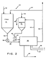
- Fig. 2 is a flow diagram of crossflow filtration system.
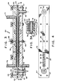
- Fig. 3 is a view in section of an embodiment of the electrically augmented crossflow filter device of the invention.
- Fig. 3A is a view taken along
line 3A-3A of Fig. 3. - Fig. 4 is a view of the crossflow filter device taken along line 4-4 of Fig. 3.
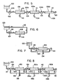
- Fig. 5 is a flow diagram of the electrically augmented crossflow filter device of the invention, shown in a single pass system for processing a feed slurry.
- Fig. 6 is a flow diagram of the electrically augmented crossflow filter device of the invention, shown in a batch-open loop system for processing a feed slurry.
- Fig. 7 is a flow diagram of the electrically augmented crossflow filter device if the invention, shown in a batch-closed loop system for processing a feed slurry.
- Fig. 8 is a flow diagram of the electrically augmented crossflow filter device of the invention, shown in a staged system for processing a feed slurry.
- Referring to the drawings, there is schematically illustrated in Fig. 1 the crossflow electrofiltration unit of this invention, including a plurality of elongated electrode assemblies arranged in parallel alignment. In this configuration, anode assemblies 11 alternate with
cathode assemblies 12 and the anode assemblies are spaced from the cathode assemblies by feed-product channels 13. The array of anode assemblies and cathode assemblies may be positioned within a confining structure asuch as the housing indicated at 14 which is provided with afeed inlet 16 and aproduct outlet 17. The direction of flow through the feed-product channel between the spaced electrodes is indicated byarrows 18. Anolyte is introduced into the anode assemblies 11 through theinlet conduit 21 and anolyte is withdrawn from the anode assemblies 11 through theoutlet conduit 22. Filtrate from the feed stream is drawn through liquid-previous faces orfilter media 23 of the cathode assemblies through thefiltrate withdrawal conduit 24.Electrical conductors cathode assemblies 12. - In operation, a flow of a feed slurry is established through the feed-
product channels 13 and a pressure differential is thereby established across thecathode filter media 23, such that the pressure in the feed-product channels exceeds the pressure within the cathode assemblies. In addition, the anode assemblies and cathode assemblies are energized by means of theelectrical conductors product channels 18. The combination of the pressure differential across thecathode filter media 23 and the electric field causes liquid from the feed slurry to pass into thecathode assemblies 12, from which it is removed through thefiltrate withdrawal conduits 24. The transport mechanism through the cathode filter medium is a combination of pressure driven and electroosmotic driven processes. At the same time, the electrical potential across the feed-product channels 13 causes the solids in the slurry to tend to move toward the anode assemblies 11. Some portion of the solids may deposit on the anode assemblies 11; however, if solids initially deposit, accretion of additional solids is limited by the erosive character of the flow of slurry inchannels 13 as it passes over the surface of the anode surface member. The cake, if any, on the anode assembly thus reaches an equilibrium thickness, dependent on the electric field strength and the flow velocity of the slurry. The anode cake, if present, tends to protect the anode surface member from abrasion and may have certain other advantages. The aforementioned tendency of the solids in the slurry to move toward the anode assembly has the advantage that little or no cake is deposited on the cathode, thus minimizing or eliminating any "blinding" of thecathode filter media 23, so that a relatively high filtrate flow may be established and maintained. - In the initial work with electrofiltration apparatus, both the liquid-pervious surfaces and the ion-pervious surfaces of the electrode assemblies were made of a woven fabric, Dynel. An unwoven fabric could also have been used. Such surfaces were operative on the cathode assemblies (the liquid-pervious surfaces), but had the characteristic, in that application, that particles in suspension would pass through the relatively "open" fabric material with the filtrate during initial operation of the electrofilter, even though the bulk of suspended solids was attracted to the anode assembly. This condition, leading to "cloudy" filtrate, would prevail until, after operation for a period of hours or days, a thin cathode cake built up on the fabric surface. The cathode cake then prevented the passage of solids and a clear filtrate would result. A fabric member is, therefore, quite serviceable for the liquid-pervious surfaces in the prior art electrofilters.
- However, in the crossflow electrofilter, the velocity of the slurry across the liquid-pervious surface is great enough to sweep away any substantial cake buildup. In this situation, then, solids will continuously pass into the filtrate channel through a fabric material with the filtrate, and this can amount to a substantial loss of product. Accordingly, a "tighter" surface is highly desirable in the crossflow electrofilter. It has been found that microporous membranes of polymer, ceramic or stainless steel or anisotropic cellulosic or polymer ultrafiltration membranes do not permit the solids to pass into the interior of the cathode assembly, while allowing the liquid filtrate, under pressure, to so pass. Membranes of this type provide a positive barrier to passage of solids and are, therefore, more suitable than fabric members for the crossflow electrofilter.
- The fabric surface was also operative at the anode assembly in the prior art electrofiltration apparatus, but had the disadvantage that anolyte was electroosmotically pumpe8 from the interior of the anode assembly into the bath of suspended solids through the cake deposited on the anode assembly, contaminating both the filter cake and the bath. The fabric surface also permitted some fine solids to pass into the anode assembly, at least until a filter cake was established on the anode assembly.
- In the system of the present invention, only a very thin cake, or no cake at all, is present on the surface of the anode assembly due to the shearing effect of the flowing slurry. Therefore, a positive barrier to entry of the fine suspended particles into the anode assembly is essential. Such positive barriers may be provided by ion exchange membranes or, as explained above, by microporous membranes or anisotropic polymeric membranes. Of these membranes, however, only the ion exchange membrane will prevent back migration or electroosmotic pumping of electrolyte through the membrane into the filter cake, if present, and into the concentrated slurry. Where back migration cannot be tolerated due to product purity considerations, then only an ion exchange membrane can be employed. Where some degree of anolyte migration into the cake or concentrated slurry is tolerable, or even desirable, the other types of membranes may be considered for use.
- In the flow diagram of Fig. 2, a
crossflow electrofiltration unit 30 is illustrated in acrossflow filtration system 40 capable of providing the necessary feed slurry and anolyte flows to theelectrofiltration unit 30. Aslurry feed tank 31 has aninlet 32 and afeed outlet conduit 33 with aslurry feed pump 35 therein. Thefeed outlet conduit 33 is connected to thecrossflow electrofiltration unit 30, where, for example, it supplies slurry to thefeed product channels 13 as shown in Fig. 1. The product stream which issues fromchannels 13 is carried away by theproduct outlet conduit 36. A portion of the product stream may be returned to thefeed tank 31 throughproduct recycle line 37. The anolyte circuit for supplying anolyte to the anode assembly members 11 (of Fig. 1) includes ananolyte tank 41 having aninlet 42 for fresh anolyte andanolyte outlet conduit 43 which has ananolyte pump 44 therein. Theanolyte outlet conduit 43 is connected to the anode assemblies 11 in thecrossflow electrofiltration unit 30. Arecycle anolyte conduit 47 is provided for returning anolyte which has passed through the anode assembly members 11 to theanolyte tank 41. A portion of the anolyte recycle may be discarded throughline 46 to maintain a constant anolyte conductivity at a fixed volume.Electrical conductors crossflow electrofiltration unit 30 for establishing the electrical potential provided across thefeed product channels 13. Thefiltrate outlet conduit 48 is provided for conducting away-the liquid which has been removed through the cathode filter media 23 (of Fig. 1). - In Fig. 3, another embodiment of the crossflow filter unit is illustrated. The
crossflow filter device 60 has anupper housing 61 and alower housing 62, which are spaced from each other by aresilient sealing gasket 63. The upper and lower housings are preferably made of an electrically non-conductive material; for example, fiberglass reinforced polyester, polysulfone, polypropylene. Alternatively, the housings may be formed of metal with an electrically non-conductive coating thereon, such as a polymer or ceramic coating layer. A plurality of conventional fastening means, such as the nuts 64,washers 94, andbolts 67, secure together theupper housing 61, thelower housing 62, and the sealinggasket 63. The sealinggasket 63 and the adjacent surfaces of theupper housing 61 andlower housing 62 define a feed-product channel 68 lying between the upper and lower housings. Recessed into theupper housing 61 is anelectrolyte channel 69 which extends along feed-product channel 68, but which does not extend the full length of the feed-product channel. At one extremity of theelectrolyte channel 69, it communicates with anelectrolyte inlet 71 which passes throughupper housing 61, while at the other extremity of theelectrolyte channel 69 it is in communication with theelectrolyte outlet 72 which also passes through theupper housing 61. Anelectrode element 79 is positioned inelectrolyte channel 69 and may take the form of an expanded metal sheet lying next against the wall of the electrolyte channel. Anon-conductive spacing element 78 is also positioned in theelectrolyte channel 69 and an ion-pervious surface member 77 is positioned overelectrolyte channel 69, and situated between thegasket 63 andhousing 61. The fastening means 64, 94 and 67 thereby secures the ion-pervious surface member 77 between thegasket 63 and thehousing 61. It will thus be seen that the ion-pervious surface member 77 separates theelectrolyte channel 69 from thefeed product channel 68. Thenonconductive spacer element 78 supports thesurface member 77 in position where it lies over theelectrolyte channel 69. - The
lower housing 62 of thecrossflow electrofiltration unit 60 is somewhat similar in configuration to theupper housing 61 in that it has afiltrate channel 81 which faces and is generally coextensive with theelectrolyte channel 69 of theupper housing 61. Infiltrate channel 81 is anelectrode element 75, and anon-conductive spacer element 74, just as in theelectrolyte channel 69. In addition, a liquid-pervious filter medium 76 is mounted between thelower housing 62 and the sealinggasket 63 in just the same manner as the ion-pervious surface member 77. Thus, the fastening means 64, 94 and 67 also functions to secure thefilter medium 76 in position, forming one wall of thefeed product channel 68. Aconductive electrode stud 82 extends throughupper housing 61 to establish electrical contact with theelectrode element 79 while asecond electrode stud 83 passes throughlower housing 62 to provide electrical connection toelectrode element 75. At one extremity of thefiltrate channel 68, it is in communication with afiltrate outlet 91 which passes through the lower housing 52. Communicating with the feed-product channel 68 beyond the ends of thefiltrate channel 81 andelectrolyte channel 69 are a threadedfeed inlet member 92 which passes through thelower housing 62 at one extremity of the feed-product channel 68 while a threadedproduct outlet member 93 communicates with the feed-product channel 68 at the opposite extremity thereof. Thebore 86 forproduct outlet 93 has a conically counter-boredupper portion 87 in whichconical flange 85 of threadedproduct outlet member 93 is seated. Thenut 65 is provided onmember 93 so that theoutlet member 93 can be drawn down to moveflange 85 toward engagement withconical surface 87. A similar arrangement is provided atfeed inlet 92. Holes are provided in thefilter medium 76 to mate with the bores at thefeed inlet member 92 andproduct outlet member 93. The edges of the fabric surrounding the holes in thefilter medium 76 are fixed between theconical surface 87 and the conical flange 8S to pravide a seal at that point so that feed slurry cannot intrude beneath thefilter medium 76. - The liquid-pervious filter medium may be a fabric, such as Dynel (a copolymer of vinyl chloride and acrylonitrile), an "open" filter. Where very fine or ultrafine particles predominate in the slurry, a microporous polymer membrane, which will retain particle sizes above 20mm, may be employed. For suspensions containing still finer particles, an anisotropic polymer ultrafiltration membrane capable of retaining particles in the range from 2 to 20mm may be used.
- In operation, a feed is introduced into the
inlet feed member 92 and flows through the feed-product channel 68 and a product flow exits thecrossflow filtration unit 60 through theproduct outlet 93. At the same time, an electrolyte is introduced into theelectrolyte channel 69 through theelectrolyte inlet 71 and passes through theelectrolyte channel 69 to exit through theelectrolyte outlet 72. An electric field is established across the feed-product channel 68 by connectingelectrode studs membrane 76 by the pumps driving the feed through thefeed product channel 68. A vacuum source can be connected to filtrateoutlet 91 to supplement the differential pressure acrossmembrane 76. A liquid component of the feed slurry passes through thefilter media 76 intofiltrate channel 81 and exits from thecrossflow filtration unit 60 through thefiltrate outlet 91. Thus, as the feed advances through the feed-product channel 68, it becomes progressively richer in the solid components thereof and, consequently, a product issues fromproduct outlet 93 which is substantially enriched in solids content when compared with the feed. - Comparative tests were performed on the crossflow electrofilter and the conventional electrofilter using a kaolin slurry feed identified as predispersed 'HT' clay, obtained from Engelhard Minerals and Chemicals Corporation, made up with various percent solids content.
- The crossflow electrofilter used in these tests employed a Dynel fabric as the cathodic surface and a cation exchange membrane as the anodic surface.
- The results obtained with the crossflow electrofilter in a device similar to that illustrated in Fig. 3 are summarized in the following Table I:


- Comparing the results of Tables I and II, it is seen that high filtration rates (see tests 2 and 3) are obtainable at high current densities in the crossflow electrofilter. Energy costs per 1000 gallons of filtrate are lower than experienced in the current electrofilter when current densities used in the crossflow filter device are roughly equal to the values employed in the current electrofilter, both the filtrate rate is then also less than that of the current electrofilter.
- Thus, in addition to a much less complex device and simpler operation, the crossflow electrofilter of the present invention makes available a wider choice of operational conditions and so is more flexible in meeting the requirements of particular applications.
- The velocity required to maintain the anode surface free of cake is a function of both the feed solids and the current density. As solids increase, the velocity required also increases. As higher current densities are used, the required velocity increases. The velocities used in Table 1 range from 4.0 ft/sec (for Test 5) to 13 ft/sec (for Test 1).
- The performance of a cross flow electro-ultrafilter was tested using a 30% by weight kaolin HT grade feed obtained from Engelhard Minerals. The feed conductivity was 1250 micromhos, the feed pH was 6.5.
- The cross flow velocity of the feed across the membrane was provided by an inlet pressure of 30 psi from a single circulating pump as described in Fig. 2. The permeate channel was placed under vacuum to increase the permeate driving pressure. The anolyte used was a Na2S04 solution adjusted to 40,000 micromhos conductivity. The anode isolating membrane was a cation ion exchange resin membrane obtained from Sybron Corp. The ultrafiltration membrane used was S-10 from Dorr-Oliver.
- The results are summarized in Table III.

- Referring now to Table III, the use of electric fields to augment the permeate rate from an ultrafiltration device is clearly demonstrated. In this case, the application of a current density of about 50 Amp/ft2 produces a permeate rate roughly 4 times greater than that obtained with no current applied. Also, an advantage of from 10 to 25 gfd in permeate rate is obtained when both electric field and vacuum are applied as contrasted to the situation when only the electric field is applied.
- There are basically four schemes for utilizing the crossflow electrofiltration process:
- As shown in Fig. 5, the feed slurry is pumped from
feed tank 100 throughconduit 102 bypump 104 tocrossflow electrofiltration cell 106. Inelectrofiltration cell 106, the feed slurry passes through parallel channels -betweenelectrode elements 101. Thecrossflow electrofiltration cells outlets last electrofiltration cell 106b of the series throughconduit 120. - In this configuration, the crossflow velocity in the channels of
cell 106 decreases as filtrate is removed. Reducing the number of parallel flow paths in thecells 106a and 106b in subsequent stages compensates for this. The staged arrangement is necessary because of pump limitations. Each stage has its own pumping station;pump 104a, positioned inconduit 103, acting on the partially concentrated slurry fromcell 106 present inconduit 103 to introduce it into cell 106a, and pump 104b inconduit 105 similarly forces the partially concentrated slurry from cell 106a on intocell 106b. The additional pumping stations increase the capital cost of such an installation. - As shown in Fig. 6, the feed is pumped by
pump 107 fromfeed tank 100 throughconduit 108 into thecrossflow electrofiltration cell 109 and returned to the feed tank throughconduit 112. Theelectrofiltration cell 109 dewaters the feed incrementally during each pass with the filtrate removed throughoutlet 114, but is sized so the degree of concentration between the feed and concentrate streams at any point in time is small. The concentrated product is obtained in this system by shutting down the process and drainingfeed tank 101. This system is the most efficient from a capital cost per unit productivity and operating cost standpoint, but introduces long residence times which may be detrimental if the solids are susceptible to shear degradation or microbiological contamination. - In Fig. 7, there is illustrated a system in which the feed from
feed tank 100 is pumped throughconduit 116 by pump 118 into a volume recirculating by means ofconduit 122 around thecrossflow electrofiltration cell 120, while the filtrate is removed throughline 124 and the product is removed throughoutlet 121 from that same volume. The recirculating concentration is constant at the desired product solids content. This is the least efficient from a pumping velocity and dewatering standpoint, but reduces residence time. - This system, as seen in Fig. 8, replaces the stages of the single pass system with closed loop stages. Thus, pump 131 in
conduit 132 introduces slurry fromfeed tank 100 into a first stage containing thecrossflow electrofiltration cell 130. A volume of slurry recirculates aboutelectrofiltration cell 130 throughconduit 136 and the pressure in the stage is incrementally increased bystage pump 134 which also increases crossflow velocity incell 130. Filtrate is removed from thecell 130 throughline 138 while concentrated slurry is removed from the circulating volume throughconduit 139. The electrofiltration cell/recirculation conduit stage is replicated in this system in a series configuration. Thus, the product or bleed of the first stage is pumped throughconduit 139 bypump 134a to thecell 130a, whileconduit 136a recirculates concentrated slurry toconduit 138. Filtrate is withdrawn fromcell 130a throughline 139a while the stage product is removed from the circulating volume of slurry throughconduit 142. The final stage is essentially identical with the preceding stages; thepump 134b,cell 130b,filtrate line 139b andrecirculating conduit 136b functioning in the same way that similar elements functioned in the prior stages. The final product of the last stage is withdrawn. throughoutlet 151. - It will be seen in this last system that a base pump pressure is provided for the
cells pump 131; that base pressure appearing at the inlet ofpump 134.Pump 134 provides an increment of pressure for the suspension incell 130 to augment the differential pressure across the liquid-pervious filter members of the cell to thereby increase the flow of filtrate. Each stage in this system has a pump for providing an increment of pressure to the base pressure of the feed entering the stage. - The processing economic benefits of the open loop system are approached, with better energy utilization and control than the single pass system. Each stage operates at a fixed concentration, the stage bleed being the feed for the next stage.
- In some cases, it may be desirable to add a dispersant to the feed to keep the slurry dispersed and to prevent plugging of the feed-product channel, which latter may be of the order of one-eighth inch in depth as measured between the opposed filter medium and the ion-pervious member. The dispersants employed may be tetrasodium pyrophosphate (TTSP) or ammonium polyacrylate, for example. The dispersant may instead be added to the anolyte; relying on electroosmotic pumping to introduce anolyte with dispersant therein into the feed-product channel.
- In some cases, the suspended solids may have a positive surface charge rather than the negative surface charge characteristic of clay and polyvinylchloride. In such a case, the anode would be provided with a filter medium, while an ion-pervious member would be provided for the cathode.
- In U.S. patent 4,107,026, referred to above, and in U.S. patent 4,246,039, issued January 10, 1981, the use of an electrofilter to concentrate a feed to a spray dryer is disclosed. The electrically augmented crossflow filter device of the present invention could, of course, be employed in a system for producing a dry powder product in combination with a spray dryer station with means, for example, a conduit, for feeding the thickened product slurry of the crossflow filter to the spray drying station.
- In the above description, various membranes have been mentioned as suitable for use under specified conditions in the crossflow electrofilter, including ion exchange membranes, microporous membranes and anisotropic polymer membranes. A suitable cationic exchange membrane is a perfluorosulfonic acid membrane which is sold under the trademark, NAFION, by E.I. DuPont de Nemours and Company. A suitable anionic exchange membrane is composed of an ammoniated polystyrene/polyvinylidene fluoride mixture on polypropylene cloth and is available from Sybron Chemicals Incorporated of Birmingham, New Jersey. Suitable microporous membranes are composed of polymers such as polysulfone prepared by a phase inversion casting technique and are available from Millipore Corporation of Lexington, Massachusetts. Anisotropic polymer membranes are also composed of polymers such as polysulfone prepared by a phase inversion casting technique as described in U.S. Patent 3,615,024, issued October 26, 1971 in the name of A.S. Michaels.
- As used herein, the term ion exchange membranes, refers to membranes which are (1) hydraulically impermeable or essentially impermeable and (2) ion conducting, i.e. able to transport ions freely under the action of an applied electric field. Such membranes can be either cation selective, passing essentially only cations, or they can be anion selective, passing only anions, and they can be non-selective, being essentially indifferent as to which ionic charge species is allowed to pass.
- Since it is possible that the pores of the cathode filter media may be blinded and clogged by the suspended solids of the slurry, the present invention also provides for a protective screen to be placed over the open cathode filter media. This screen permits the free flow of filtrate into the cathode structure while also allowing a gel or thin layer of suspended solids to form on the screen without penetrating, blinding or clogging the pores of the filter media. The screen preferably should be of an inert (plastic) material such as polypropylene. It should also have holes whose diameters are less than their length.
- Although the present invention has been described in conjunction with preferred embodiments, it is to be understood that modification and variation may be resorted to without departing from the spirit and scope of the invention, as those skilled in the art will readily understand.
Claims (28)
Applications Claiming Priority (2)
| Application Number | Priority Date | Filing Date | Title |
|---|---|---|---|
| US06/728,957 US4604174A (en) | 1985-04-30 | 1985-04-30 | High flow electrofiltration |
| US728957 | 1985-04-30 |
Publications (2)
| Publication Number | Publication Date |
|---|---|
| EP0203713A2 true EP0203713A2 (en) | 1986-12-03 |
| EP0203713A3 EP0203713A3 (en) | 1987-09-16 |
Family
ID=24928956
Family Applications (1)
| Application Number | Title | Priority Date | Filing Date |
|---|---|---|---|
| EP86303109A Withdrawn EP0203713A3 (en) | 1985-04-30 | 1986-04-24 | High flow electrofiltration |
Country Status (6)
| Country | Link |
|---|---|
| US (1) | US4604174A (en) |
| EP (1) | EP0203713A3 (en) |
| JP (1) | JPS61293506A (en) |
| KR (1) | KR860007952A (en) |
| AU (1) | AU579724B2 (en) |
| ZA (1) | ZA863239B (en) |
Cited By (5)
| Publication number | Priority date | Publication date | Assignee | Title |
|---|---|---|---|---|
| EP0269628A4 (en) * | 1985-08-15 | 1988-07-29 | Commw Scient Ind Res Org | Electrode-drain structures for dewatering of suspensions. |
| GB2284598A (en) * | 1993-12-07 | 1995-06-14 | Tioxide Group Services Ltd | Dewatering titanium dioxide slurries by cross-flow filtration |
| US5622628A (en) * | 1993-12-07 | 1997-04-22 | Tioxide Group Services Limited | Titanium dioxide slurries concentration |
| US5672201A (en) * | 1995-03-11 | 1997-09-30 | Tioxide Group Services Limited | Composite pigmentary material |
| DE10063097A1 (en) * | 2000-12-18 | 2002-07-04 | Gerhard Weber | Carrier-free electrophoresis method and electrophoresis device for performing this method |
Families Citing this family (28)
| Publication number | Priority date | Publication date | Assignee | Title |
|---|---|---|---|---|
| FR2567914B1 (en) * | 1984-07-19 | 1989-04-07 | Univ Languedoc | METHOD FOR THE CONTINUOUS RECOVERY OF METAL CATIONS FROM DILUTED SOLUTIONS AND APPARATUS FOR IMPLEMENTING SAME |
| US4758319A (en) * | 1985-05-24 | 1988-07-19 | Dorr-Oliver Incorporated | Dialyzing crossflow electrofilter with improved electrode |
| US5043048A (en) * | 1987-07-17 | 1991-08-27 | Muralidhara Harapanahalli S | Electromembrane apparatus and process for preventing membrane fouling |
| US5064515A (en) * | 1987-07-17 | 1991-11-12 | Battelle Memorial Institute | Electrofilter apparatus and process for preventing filter fouling in crossflow filtration |
| US5227349A (en) * | 1989-09-20 | 1993-07-13 | Ecc International Inc. | Process for producing a kaolin clay product |
| US5098583A (en) * | 1990-06-04 | 1992-03-24 | Ecc America Inc. | Method for producing high solids slurries of clay water products |
| US20030206837A1 (en) | 1998-11-05 | 2003-11-06 | Taylor Charles E. | Electro-kinetic air transporter and conditioner device with enhanced maintenance features and enhanced anti-microorganism capability |
| US6176977B1 (en) | 1998-11-05 | 2001-01-23 | Sharper Image Corporation | Electro-kinetic air transporter-conditioner |
| US7220295B2 (en) | 2003-05-14 | 2007-05-22 | Sharper Image Corporation | Electrode self-cleaning mechanisms with anti-arc guard for electro-kinetic air transporter-conditioner devices |
| US7318856B2 (en) | 1998-11-05 | 2008-01-15 | Sharper Image Corporation | Air treatment apparatus having an electrode extending along an axis which is substantially perpendicular to an air flow path |
| US7695690B2 (en) | 1998-11-05 | 2010-04-13 | Tessera, Inc. | Air treatment apparatus having multiple downstream electrodes |
| US6544485B1 (en) | 2001-01-29 | 2003-04-08 | Sharper Image Corporation | Electro-kinetic device with enhanced anti-microorganism capability |
| US20050210902A1 (en) | 2004-02-18 | 2005-09-29 | Sharper Image Corporation | Electro-kinetic air transporter and/or conditioner devices with features for cleaning emitter electrodes |
| US7405672B2 (en) | 2003-04-09 | 2008-07-29 | Sharper Image Corp. | Air treatment device having a sensor |
| US7077890B2 (en) | 2003-09-05 | 2006-07-18 | Sharper Image Corporation | Electrostatic precipitators with insulated driver electrodes |
| US7906080B1 (en) | 2003-09-05 | 2011-03-15 | Sharper Image Acquisition Llc | Air treatment apparatus having a liquid holder and a bipolar ionization device |
| US7724492B2 (en) | 2003-09-05 | 2010-05-25 | Tessera, Inc. | Emitter electrode having a strip shape |
| US20050051420A1 (en) | 2003-09-05 | 2005-03-10 | Sharper Image Corporation | Electro-kinetic air transporter and conditioner devices with insulated driver electrodes |
| US7517503B2 (en) | 2004-03-02 | 2009-04-14 | Sharper Image Acquisition Llc | Electro-kinetic air transporter and conditioner devices including pin-ring electrode configurations with driver electrode |
| US7767169B2 (en) | 2003-12-11 | 2010-08-03 | Sharper Image Acquisition Llc | Electro-kinetic air transporter-conditioner system and method to oxidize volatile organic compounds |
| US7638104B2 (en) | 2004-03-02 | 2009-12-29 | Sharper Image Acquisition Llc | Air conditioner device including pin-ring electrode configurations with driver electrode |
| US7285155B2 (en) | 2004-07-23 | 2007-10-23 | Taylor Charles E | Air conditioner device with enhanced ion output production features |
| US20060016333A1 (en) | 2004-07-23 | 2006-01-26 | Sharper Image Corporation | Air conditioner device with removable driver electrodes |
| US7311762B2 (en) | 2004-07-23 | 2007-12-25 | Sharper Image Corporation | Air conditioner device with a removable driver electrode |
| US7833322B2 (en) | 2006-02-28 | 2010-11-16 | Sharper Image Acquisition Llc | Air treatment apparatus having a voltage control device responsive to current sensing |
| JP5593786B2 (en) * | 2010-03-31 | 2014-09-24 | 栗田工業株式会社 | Electroosmotic dehydration method |
| CN103463985B (en) * | 2013-09-10 | 2015-07-01 | 内蒙古天一环境技术有限公司 | Osmosis membrane assembly for dielectrophoresis forward-osmosis flat plate |
| US11377377B2 (en) * | 2020-06-24 | 2022-07-05 | Wenhou University | Horizontal-vertical drain board-flocculation vacuum preloading sediment treatment method |
Family Cites Families (14)
| Publication number | Priority date | Publication date | Assignee | Title |
|---|---|---|---|---|
| US3079318A (en) * | 1959-01-15 | 1963-02-26 | Bier Milan | Electrical filtering process and device |
| DE1205491B (en) * | 1959-01-15 | 1965-11-25 | Dr Milan Bier | Method and device for the continuous electrophoretic treatment of suspensions and colloidal solutions |
| US3657106A (en) * | 1969-06-05 | 1972-04-18 | American Bioculture | Electro-osmosis system |
| US3718559A (en) * | 1970-03-27 | 1973-02-27 | R Wallace | Electrogel process for removing electrolytes and concentrating the same from an aqueous solution |
| US3870617A (en) * | 1971-03-30 | 1975-03-11 | Rhone Poulenc Sa | Apparatus for forced flow electrophoresis |
| US4043895A (en) * | 1973-05-16 | 1977-08-23 | The Dow Chemical Company | Electrophoresis apparatus |
| US4043896A (en) * | 1976-03-25 | 1977-08-23 | Aqua-Chem, Inc. | Ultrafiltration and electrodialysis apparatus |
| US4170529A (en) * | 1976-06-17 | 1979-10-09 | Dorr-Oliver Incorporated | System and method for electric dewatering of solids suspension |
| US4107026A (en) * | 1976-06-17 | 1978-08-15 | Dorr-Oliver Incorporated | System and method for electric dewatering of solids suspension |
| US4207158A (en) * | 1976-06-17 | 1980-06-10 | Dorr-Oliver Incorporated | Electrically augmented vacuum filtration |
| US4204929A (en) * | 1978-04-18 | 1980-05-27 | University Patents, Inc. | Isoelectric focusing method |
| US4248686A (en) * | 1979-12-06 | 1981-02-03 | The United States Of America As Represented By The United States Department Of Energy | Cross flow electrofilter and method |
| US4468303A (en) * | 1981-12-04 | 1984-08-28 | Norcim Investments Pty Ltd. | Metal recovery |
| US4468306A (en) * | 1983-04-06 | 1984-08-28 | Dorr-Oliver Incorporated | Biodic electrofiltration |
-
1985
- 1985-04-30 US US06/728,957 patent/US4604174A/en not_active Expired - Fee Related
-
1986
- 1986-04-22 AU AU56472/86A patent/AU579724B2/en not_active Expired - Fee Related
- 1986-04-24 EP EP86303109A patent/EP0203713A3/en not_active Withdrawn
- 1986-04-25 JP JP61094961A patent/JPS61293506A/en active Pending
- 1986-04-29 KR KR1019860003317A patent/KR860007952A/en not_active Withdrawn
- 1986-04-30 ZA ZA863239A patent/ZA863239B/en unknown
Cited By (11)
| Publication number | Priority date | Publication date | Assignee | Title |
|---|---|---|---|---|
| EP0269628A4 (en) * | 1985-08-15 | 1988-07-29 | Commw Scient Ind Res Org | Electrode-drain structures for dewatering of suspensions. |
| GB2284598A (en) * | 1993-12-07 | 1995-06-14 | Tioxide Group Services Ltd | Dewatering titanium dioxide slurries by cross-flow filtration |
| US5622628A (en) * | 1993-12-07 | 1997-04-22 | Tioxide Group Services Limited | Titanium dioxide slurries concentration |
| GB2284598B (en) * | 1993-12-07 | 1997-07-30 | Tioxide Group Services Ltd | Titanium dioxide slurries |
| AU680697B2 (en) * | 1993-12-07 | 1997-08-07 | Tioxide Group Services Limited | Titanium dioxide slurries |
| US5672201A (en) * | 1995-03-11 | 1997-09-30 | Tioxide Group Services Limited | Composite pigmentary material |
| DE10063097A1 (en) * | 2000-12-18 | 2002-07-04 | Gerhard Weber | Carrier-free electrophoresis method and electrophoresis device for performing this method |
| WO2002050524A3 (en) * | 2000-12-18 | 2002-12-27 | Gerhard Weber | Free flow electrophoresis method and electrophoresis device for carrying out this method |
| DE10063097B4 (en) * | 2000-12-18 | 2007-04-19 | Becton, Dickinson And Co. | electrophoresis |
| EP1845370A1 (en) * | 2000-12-18 | 2007-10-17 | Becton, Dickinson & Company | Carrier-free electrophoresis method and electrophoresis device for performing this method |
| US7491304B2 (en) | 2000-12-18 | 2009-02-17 | Becton, Dickinson And Company | Carrierless electrophoresis process and electrophoresis device for carrying out this process |
Also Published As
| Publication number | Publication date |
|---|---|
| AU579724B2 (en) | 1988-12-08 |
| ZA863239B (en) | 1986-12-30 |
| EP0203713A3 (en) | 1987-09-16 |
| JPS61293506A (en) | 1986-12-24 |
| AU5647286A (en) | 1986-11-06 |
| KR860007952A (en) | 1986-11-10 |
| US4604174A (en) | 1986-08-05 |
Similar Documents
| Publication | Publication Date | Title |
|---|---|---|
| US4604174A (en) | High flow electrofiltration | |
| US4124458A (en) | Mass-transfer membrane and processes using same | |
| US5334300A (en) | Turbulent flow electrodialysis cell | |
| US4569739A (en) | Electrofilter using an improved electrode assembly | |
| Bowen et al. | Electrically enhanced separation processes: the basis of in situ intermittent electrolytic membrane cleaning (IIEMC) and in situ electrolytic membrane restoration (IEMR) | |
| US4003811A (en) | Electrokinetic separation of solid particles from aqueous suspensions thereof | |
| US4468306A (en) | Biodic electrofiltration | |
| US4132626A (en) | Electroflocculation cell | |
| US5171409A (en) | Continuous process of separating electrically charged solid, pulverulent particles by electrophoresis and electroosmosis | |
| US4758319A (en) | Dialyzing crossflow electrofilter with improved electrode | |
| US3577331A (en) | Apparatus and process for effecting changes in solution concentrations | |
| EP0380266A1 (en) | Filter cleaning | |
| SU1118389A1 (en) | Electric dialyzer | |
| US4248686A (en) | Cross flow electrofilter and method | |
| CA2247386A1 (en) | Membrane filter with electrical and/or acoustic enhancement | |
| US4224135A (en) | Cross-flow electrofilter and method | |
| AU601447B2 (en) | A continuous process of separating electrically charged solid, pulverulent particle by electrophoresis and electroosmosis | |
| US4639300A (en) | Method and apparatus for electrofiltration | |
| US4668361A (en) | Dialyzing electrofilter with improved electrode | |
| GB2315426A (en) | Membrane Filters | |
| US4693802A (en) | Electrically augmented vacuum filtration apparatus for producing a dialyzed cake product | |
| EP0084582B1 (en) | Dewatering with electrically augmented vacuum filter | |
| US3748244A (en) | Process and apparatus for electric cell treatment of liquor | |
| US3766039A (en) | Process for treatment of liquors using multi-compartment baths | |
| JPS58153514A (en) | Electrode assembly equipped with ion exchange membrane |
Legal Events
| Date | Code | Title | Description |
|---|---|---|---|
| PUAI | Public reference made under article 153(3) epc to a published international application that has entered the european phase |
Free format text: ORIGINAL CODE: 0009012 |
|
| AK | Designated contracting states |
Kind code of ref document: A2 Designated state(s): AT BE CH DE FR GB IT LI LU NL SE |
|
| PUAL | Search report despatched |
Free format text: ORIGINAL CODE: 0009013 |
|
| AK | Designated contracting states |
Kind code of ref document: A3 Designated state(s): AT BE CH DE FR GB IT LI LU NL SE |
|
| 17P | Request for examination filed |
Effective date: 19880302 |
|
| 17Q | First examination report despatched |
Effective date: 19900313 |
|
| STAA | Information on the status of an ep patent application or granted ep patent |
Free format text: STATUS: THE APPLICATION IS DEEMED TO BE WITHDRAWN |
|
| 18D | Application deemed to be withdrawn |
Effective date: 19900629 |
|
| RIN1 | Information on inventor provided before grant (corrected) |
Inventor name: KLINKOWSKI, PETER, R. Inventor name: BOLLINGER, JAMES M. |