EP0203489A2 - Improved hollow fiber membrane device with inner wrap - Google Patents
Improved hollow fiber membrane device with inner wrap Download PDFInfo
- Publication number
- EP0203489A2 EP0203489A2 EP86106782A EP86106782A EP0203489A2 EP 0203489 A2 EP0203489 A2 EP 0203489A2 EP 86106782 A EP86106782 A EP 86106782A EP 86106782 A EP86106782 A EP 86106782A EP 0203489 A2 EP0203489 A2 EP 0203489A2
- Authority
- EP
- European Patent Office
- Prior art keywords
- hollow fiber
- membrane device
- fibers
- wrap
- distribution means
- Prior art date
- Legal status (The legal status is an assumption and is not a legal conclusion. Google has not performed a legal analysis and makes no representation as to the accuracy of the status listed.)
- Withdrawn
Links
- 239000012510 hollow fiber Substances 0.000 title claims abstract description 137
- 239000012528 membrane Substances 0.000 title claims abstract description 124
- 239000000835 fiber Substances 0.000 claims abstract description 88
- 238000009826 distribution Methods 0.000 claims description 38
- 239000012530 fluid Substances 0.000 claims description 33
- 239000000463 material Substances 0.000 claims description 28
- IJGRMHOSHXDMSA-UHFFFAOYSA-N Atomic nitrogen Chemical compound N#N IJGRMHOSHXDMSA-UHFFFAOYSA-N 0.000 claims description 21
- 239000007789 gas Substances 0.000 claims description 18
- 239000000203 mixture Substances 0.000 claims description 17
- 239000012466 permeate Substances 0.000 claims description 16
- QVGXLLKOCUKJST-UHFFFAOYSA-N atomic oxygen Chemical compound [O] QVGXLLKOCUKJST-UHFFFAOYSA-N 0.000 claims description 12
- 239000001301 oxygen Substances 0.000 claims description 12
- 229910052760 oxygen Inorganic materials 0.000 claims description 12
- 239000004744 fabric Substances 0.000 claims description 11
- 238000000034 method Methods 0.000 claims description 10
- 229910052757 nitrogen Inorganic materials 0.000 claims description 10
- 229920000642 polymer Polymers 0.000 claims description 9
- 229920000098 polyolefin Polymers 0.000 claims description 6
- WSSSPWUEQFSQQG-UHFFFAOYSA-N 4-methyl-1-pentene Chemical compound CC(C)CC=C WSSSPWUEQFSQQG-UHFFFAOYSA-N 0.000 claims description 5
- 239000007787 solid Substances 0.000 claims description 4
- 230000008569 process Effects 0.000 claims description 3
- 150000001336 alkenes Chemical class 0.000 claims description 2
- 229930195733 hydrocarbon Natural products 0.000 claims description 2
- 150000002430 hydrocarbons Chemical class 0.000 claims description 2
- 239000004745 nonwoven fabric Substances 0.000 claims description 2
- 239000004215 Carbon black (E152) Substances 0.000 claims 1
- 125000005375 organosiloxane group Chemical group 0.000 claims 1
- 238000000926 separation method Methods 0.000 description 15
- -1 polyethylene Polymers 0.000 description 7
- 238000011084 recovery Methods 0.000 description 5
- CURLTUGMZLYLDI-UHFFFAOYSA-N Carbon dioxide Chemical compound O=C=O CURLTUGMZLYLDI-UHFFFAOYSA-N 0.000 description 4
- 229920002466 Dynel Polymers 0.000 description 3
- 239000004698 Polyethylene Substances 0.000 description 3
- 229920002678 cellulose Polymers 0.000 description 3
- 229920002301 cellulose acetate Polymers 0.000 description 3
- 230000008859 change Effects 0.000 description 3
- 230000000052 comparative effect Effects 0.000 description 3
- 239000003822 epoxy resin Substances 0.000 description 3
- 238000002474 experimental method Methods 0.000 description 3
- 238000003780 insertion Methods 0.000 description 3
- 230000037431 insertion Effects 0.000 description 3
- 230000035699 permeability Effects 0.000 description 3
- 229920000647 polyepoxide Polymers 0.000 description 3
- 229920000728 polyester Polymers 0.000 description 3
- 229920000573 polyethylene Polymers 0.000 description 3
- 239000011148 porous material Substances 0.000 description 3
- 238000007789 sealing Methods 0.000 description 3
- 239000004677 Nylon Substances 0.000 description 2
- 239000004952 Polyamide Substances 0.000 description 2
- 230000002411 adverse Effects 0.000 description 2
- 230000015572 biosynthetic process Effects 0.000 description 2
- 239000001569 carbon dioxide Substances 0.000 description 2
- 229910002092 carbon dioxide Inorganic materials 0.000 description 2
- 238000001816 cooling Methods 0.000 description 2
- 230000006866 deterioration Effects 0.000 description 2
- 238000003754 machining Methods 0.000 description 2
- 238000004519 manufacturing process Methods 0.000 description 2
- 229910052751 metal Inorganic materials 0.000 description 2
- 239000002184 metal Substances 0.000 description 2
- 239000007769 metal material Substances 0.000 description 2
- 239000003607 modifier Substances 0.000 description 2
- 229920001778 nylon Polymers 0.000 description 2
- 229920003023 plastic Polymers 0.000 description 2
- 239000004033 plastic Substances 0.000 description 2
- 229920002647 polyamide Polymers 0.000 description 2
- 229920005989 resin Polymers 0.000 description 2
- 239000011347 resin Substances 0.000 description 2
- 238000001223 reverse osmosis Methods 0.000 description 2
- 238000009987 spinning Methods 0.000 description 2
- 229920002994 synthetic fiber Polymers 0.000 description 2
- 229920001169 thermoplastic Polymers 0.000 description 2
- 229920001187 thermosetting polymer Polymers 0.000 description 2
- RWSOTUBLDIXVET-UHFFFAOYSA-N Dihydrogen sulfide Chemical compound S RWSOTUBLDIXVET-UHFFFAOYSA-N 0.000 description 1
- 239000004593 Epoxy Substances 0.000 description 1
- 229920000459 Nitrile rubber Polymers 0.000 description 1
- 239000005062 Polybutadiene Substances 0.000 description 1
- 229920002367 Polyisobutene Polymers 0.000 description 1
- 239000004721 Polyphenylene oxide Substances 0.000 description 1
- 239000004743 Polypropylene Substances 0.000 description 1
- 229920000297 Rayon Polymers 0.000 description 1
- 125000000218 acetic acid group Chemical group C(C)(=O)* 0.000 description 1
- 239000002253 acid Substances 0.000 description 1
- 239000000654 additive Substances 0.000 description 1
- 229910052782 aluminium Inorganic materials 0.000 description 1
- XAGFODPZIPBFFR-UHFFFAOYSA-N aluminium Chemical compound [Al] XAGFODPZIPBFFR-UHFFFAOYSA-N 0.000 description 1
- 230000008901 benefit Effects 0.000 description 1
- NTXGQCSETZTARF-UHFFFAOYSA-N buta-1,3-diene;prop-2-enenitrile Chemical compound C=CC=C.C=CC#N NTXGQCSETZTARF-UHFFFAOYSA-N 0.000 description 1
- 229920003086 cellulose ether Polymers 0.000 description 1
- 238000009750 centrifugal casting Methods 0.000 description 1
- 238000006243 chemical reaction Methods 0.000 description 1
- 239000003795 chemical substances by application Substances 0.000 description 1
- 238000002485 combustion reaction Methods 0.000 description 1
- 238000004891 communication Methods 0.000 description 1
- 238000005056 compaction Methods 0.000 description 1
- 229920001577 copolymer Polymers 0.000 description 1
- 230000001351 cycling effect Effects 0.000 description 1
- 230000007423 decrease Effects 0.000 description 1
- ZBCBWPMODOFKDW-UHFFFAOYSA-N diethanolamine Chemical compound OCCNCCO ZBCBWPMODOFKDW-UHFFFAOYSA-N 0.000 description 1
- 229910001873 dinitrogen Inorganic materials 0.000 description 1
- 150000002170 ethers Chemical class 0.000 description 1
- 238000001125 extrusion Methods 0.000 description 1
- 239000011888 foil Substances 0.000 description 1
- LNEPOXFFQSENCJ-UHFFFAOYSA-N haloperidol Chemical compound C1CC(O)(C=2C=CC(Cl)=CC=2)CCN1CCCC(=O)C1=CC=C(F)C=C1 LNEPOXFFQSENCJ-UHFFFAOYSA-N 0.000 description 1
- 238000010438 heat treatment Methods 0.000 description 1
- 229910000037 hydrogen sulfide Inorganic materials 0.000 description 1
- 230000006872 improvement Effects 0.000 description 1
- 239000007788 liquid Substances 0.000 description 1
- 239000004850 liquid epoxy resins (LERs) Substances 0.000 description 1
- 239000006193 liquid solution Substances 0.000 description 1
- 239000000155 melt Substances 0.000 description 1
- 239000002343 natural gas well Substances 0.000 description 1
- 229920000620 organic polymer Polymers 0.000 description 1
- 230000000704 physical effect Effects 0.000 description 1
- 239000002985 plastic film Substances 0.000 description 1
- 229920006255 plastic film Polymers 0.000 description 1
- 239000004014 plasticizer Substances 0.000 description 1
- 229920001200 poly(ethylene-vinyl acetate) Polymers 0.000 description 1
- 229920002492 poly(sulfone) Polymers 0.000 description 1
- 229920002857 polybutadiene Polymers 0.000 description 1
- 239000004417 polycarbonate Substances 0.000 description 1
- 229920000515 polycarbonate Polymers 0.000 description 1
- 229920000139 polyethylene terephthalate Polymers 0.000 description 1
- 239000005020 polyethylene terephthalate Substances 0.000 description 1
- 229920000306 polymethylpentene Polymers 0.000 description 1
- 229920006380 polyphenylene oxide Polymers 0.000 description 1
- 229920001155 polypropylene Polymers 0.000 description 1
- 239000004800 polyvinyl chloride Substances 0.000 description 1
- 229920000915 polyvinyl chloride Polymers 0.000 description 1
- 229920000036 polyvinylpyrrolidone Polymers 0.000 description 1
- 239000001267 polyvinylpyrrolidone Substances 0.000 description 1
- 235000013855 polyvinylpyrrolidone Nutrition 0.000 description 1
- 239000002964 rayon Substances 0.000 description 1
- 239000000376 reactant Substances 0.000 description 1
- 230000009467 reduction Effects 0.000 description 1
- 229920003048 styrene butadiene rubber Polymers 0.000 description 1
- 239000004416 thermosoftening plastic Substances 0.000 description 1
- 238000009827 uniform distribution Methods 0.000 description 1
- 239000002759 woven fabric Substances 0.000 description 1
- 239000004711 α-olefin Substances 0.000 description 1
Images
Classifications
-
- B—PERFORMING OPERATIONS; TRANSPORTING
- B01—PHYSICAL OR CHEMICAL PROCESSES OR APPARATUS IN GENERAL
- B01D—SEPARATION
- B01D63/00—Apparatus in general for separation processes using semi-permeable membranes
- B01D63/02—Hollow fibre modules
- B01D63/04—Hollow fibre modules comprising multiple hollow fibre assemblies
- B01D63/043—Hollow fibre modules comprising multiple hollow fibre assemblies with separate tube sheets
-
- B—PERFORMING OPERATIONS; TRANSPORTING
- B01—PHYSICAL OR CHEMICAL PROCESSES OR APPARATUS IN GENERAL
- B01D—SEPARATION
- B01D63/00—Apparatus in general for separation processes using semi-permeable membranes
- B01D63/02—Hollow fibre modules
- B01D63/04—Hollow fibre modules comprising multiple hollow fibre assemblies
-
- B—PERFORMING OPERATIONS; TRANSPORTING
- B01—PHYSICAL OR CHEMICAL PROCESSES OR APPARATUS IN GENERAL
- B01D—SEPARATION
- B01D63/00—Apparatus in general for separation processes using semi-permeable membranes
- B01D63/02—Hollow fibre modules
-
- B—PERFORMING OPERATIONS; TRANSPORTING
- B01—PHYSICAL OR CHEMICAL PROCESSES OR APPARATUS IN GENERAL
- B01D—SEPARATION
- B01D63/00—Apparatus in general for separation processes using semi-permeable membranes
- B01D63/02—Hollow fibre modules
- B01D63/033—Specific distribution of fibres within one potting or tube-sheet
-
- B—PERFORMING OPERATIONS; TRANSPORTING
- B01—PHYSICAL OR CHEMICAL PROCESSES OR APPARATUS IN GENERAL
- B01D—SEPARATION
- B01D69/00—Semi-permeable membranes for separation processes or apparatus characterised by their form, structure or properties; Manufacturing processes specially adapted therefor
- B01D69/10—Supported membranes; Membrane supports
- B01D69/107—Organic support material
- B01D69/1071—Woven, non-woven or net mesh
-
- B—PERFORMING OPERATIONS; TRANSPORTING
- B01—PHYSICAL OR CHEMICAL PROCESSES OR APPARATUS IN GENERAL
- B01D—SEPARATION
- B01D71/00—Semi-permeable membranes for separation processes or apparatus characterised by the material; Manufacturing processes specially adapted therefor
- B01D71/06—Organic material
- B01D71/26—Polyalkenes
-
- B—PERFORMING OPERATIONS; TRANSPORTING
- B01—PHYSICAL OR CHEMICAL PROCESSES OR APPARATUS IN GENERAL
- B01D—SEPARATION
- B01D2313/00—Details relating to membrane modules or apparatus
- B01D2313/02—Specific tightening or locking mechanisms
- B01D2313/025—Specific membrane holders
-
- B—PERFORMING OPERATIONS; TRANSPORTING
- B01—PHYSICAL OR CHEMICAL PROCESSES OR APPARATUS IN GENERAL
- B01D—SEPARATION
- B01D2313/00—Details relating to membrane modules or apparatus
- B01D2313/10—Specific supply elements
-
- B—PERFORMING OPERATIONS; TRANSPORTING
- B01—PHYSICAL OR CHEMICAL PROCESSES OR APPARATUS IN GENERAL
- B01D—SEPARATION
- B01D2313/00—Details relating to membrane modules or apparatus
- B01D2313/23—Specific membrane protectors, e.g. sleeves or screens
-
- B—PERFORMING OPERATIONS; TRANSPORTING
- B01—PHYSICAL OR CHEMICAL PROCESSES OR APPARATUS IN GENERAL
- B01D—SEPARATION
- B01D2319/00—Membrane assemblies within one housing
- B01D2319/06—Use of membranes of different materials or properties within one module
Definitions
- This invention relates to an improved hollow fiber membrane device in which a comparatively thin material surrounds and constrains a plurality of inner fibers assembled about a feed flow distribution means.
- U.S. Patent No. 3,339,341 describes a conventional hollow fiber membrane device in which a flexible, porous sleeve member encloses the fibers. Preferred is a circular knit fabric sleeve. This sleeve is used to facilitate insertion of the fiber bundle in the pressure vessel and to provide the desired reduction in cross-sectional area of the bundles during insertion.
- U.S. Patent No. 3,526,001 discloses the use of a flexible porous sleeve over a hollow fiber membrane bundle as an aid in handling.
- U.S. Patent No. 4,380,460 discloses a membrane device in which a slit tube surrounds the hollow fiber bundle, but this tube is expanded to contact the inner surface of the housing of said device. It follows that the slit tube does not greatly restrain movement of the hollow fibers. The slit tube is intended to shield the fiber bundle from scale and other debris on the housing inner surface.
- U.S. Patent No. 4,421,529 describes a method of operating intermittently membrane gas separation devices so as to reduce deterioration of performance. ft is disclosed therein that a porous polymer outer wrap may be employed around the bundle to prevent shifting of the fibers.
- a DYNEL cloth outerwrap was used in the examples. DYNEL is a woven polyester fabric sold by Lamports Filter Media, Inc. of Cleveland, Ohio.
- U.S. Patent No. 3,690,465 describes a hollow fiber membrane device assembled about a porous polyolefin core which comprises thin layers of substantially parallel hollow fibers separated by thin foraminous materials which restrict movement of the fibers and prevent nesting. The presence of the foraminous material significantly reduces the volume productivity of such a device.
- Hollow fiber membrane devices are used for selective separation of at least one fluid component from a mixture of fluids or a solution.
- Such devices generally comprise a plurality of hollow fiber membranes, said membranes being selectively permeable to at least one component of the fluid mixture.
- the hollow fiber membranes are disposed inside a housing.
- the housing has at least one inlet for bringing a fluid feed into contact with one surface of the hollow fiber membranes. A means to promote uniform distribution of the fluid feed is desirable.
- At least one outlet for discharge of the fluid which does not permeate through the membrane and at least one outlet for fluid which permeates through the membrane is also required.
- the hollow fibers are embedded in at least one tubesheet.
- the fiber bores communicate with the permeate outlet from the housing.
- the tubesheet sealingly engages the inner surface of the housing.
- the present invention is directed toward an improved hollow fiber membrane device of the type which comprises a plurality of hollow fiber membranes assembled in a bundle about a feed flow distribution means with the membranes emtedded in at least one tubesheet and the lumens of the fibers communicating through this tubesheet.
- the improvement comprises at least one wrap of a material enveloping a major portion of the longitudinal dimension of a plurality of inner fibers assembled about the feed flow distribution means.
- the wrap is positioned at a distance from the feed flow distribution means not greater than 25 percent of the longest cord through a cross-section of the outer surface of the hollow fiber bundle perpendicular to the longitudinal axis of the bundle.
- the wrap in normal operation of the device constrains movement of the fibers within the wrap, but is foraminous or contains other openings which permit passage of feed fluid through the inner fibers to the hollow fiber membranes.
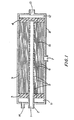
- Figure 1 is a schematic cross-section of a hollow fiber membrane device representing an embodiment of the subject invention.
- Hollow fiber membrane devices for the separation of a fluid component from a mixture or solution are well known in the prior art.
- U.S.P. Nos. 3,228,876, 3,455,460 and 4,061,574 describe such devices.
- the fluid feed can suitably be a liquid solution, as is the case in reverse osmosis.
- the subject improved membrane device is characterized by a constraining wrap and is especially preferred for the separation of gas mixtures.
- the hollow fibers in the membrane device are typically assembled about a central, perforated conduit or equivalent feed flow distribution means.
- the perforations in the core should be disposed so as to promote essentially uniform radial outward flow through the hollow fiber bundle.
- the feed flow distribution means comprises a porous polyolefin conduit which serves to buffer changes in flow rate and evenly distribute the flow.
- Assembled about the feed flow distribution means are fibers enveloped by a constraining wrap.
- These inner fibers can be hollow or solid and can be the same or a different composition from that of the hollow fiber membranes.
- the inner fibers are the same composition as the hollow fiber membrane, but the lumens of the inner fibers closest to the feed flow distribution means are sealed so that the bores of the inner fibers do not communicate through the tubesheet.
- the constraining wrap is a flexible, porous material, hereinafter referred to as a foraminous material or wrap.
- the foraminous material should have sufficient physical strength that it both maintains its integrity and constrains the inner fibers during normal operation of the membrane device.
- the statement that the foraminous wrap envelopes a plurality of fibers refers to the fact that a line drawn from a point on the feed flow distribution means to the closest outer surface of the hollow fiber bundle would normally pass through sequentially a plurality of inner fibers - (preferably, at least 100 fibers), the foraminous wrap and then a plurality of hollow fibers.
- the inner constraining wrap is disposed generally concentrically about the feed flow distribution means.
- the inner constraining wrap can be any convenient configuration so long as the desired restraint on movement of the inner fibers is provided.
- the constraining wrap can be a tubular sleeve, a relatively narrow strip of foraminous material wrapped in a helix about inner fibers assembled concentrically about the feed flow distribution means, or a strip of material of roughly the same width as the longitudinal dimension of the exposed outer surface of the hollow fiber bundle and said strip is wrapped about the inner fibers in a tubular manner. Where necessary, the tension of the constraining wrap is maintained by securing it in the tubesheet or other conventional means.
- the constraining wrap is a sheet of material, which when viewed in a cross-section perpendicular to the longitudinal axis of the bundle the wrap spirals outward from the flow distribution means.
- the wrap may be introduced contemporaneous with assembly of the bundle, particularly where the bundle is assembled as in U.S. Patent 3,755,034.
- the constraining wrap can be non-porous or not foraminous; however, a porous or foraminous material is preferred.
- the hollow fiber membranes Assembled about the foraminous wrap are the hollow fiber membranes. Both the hollow fiber membranes and the inner fibers can be parallel to or wound in a helix about the flow distribution means.
- the helical configuration is described in U.S. Patent No. 3,422,008, which is incorporated herein by reference.
- the subject invention is generally most effective when employed in a device having hollow fiber membranes disposed in a parallel fashion.
- the longitudinal axis of the bundle can be arcuate, although it is preferred this axis is linear.
- a tubesheet is usually formed near at least one end of the hollow fiber bundle, while a tubesheet or endsheet is advantageously present near the opposite ends of the fibers.
- the tubesheet and endsheet are conventionally made from an epoxy or other thermosetting resin.
- the tubesheet and endsheet or the tubesheets are sealingly engaged with a pressure casing.
- the tubesheet and endsheet together with the pressure casing define a space external to the hollow fibers, which does not communicate directly with the bores of the hollow fibers.
- the invention is not limited to any particular configuration of a hollow fiber membrane separation device.
- the standard configuration described above is preferred.
- the feed fluid to be separated flows from inside the fiber bundle external to the fibers outward.
- the hollow fibers may be arranged such that both ends of the fiber protrude through a single tubesheet or a single central tubesheet may be used.
- Figure 1 depicts in cross-section for purposes of illustration a hollow fiber membrane separation device that depicts an embodiment of this invention.
- the fluid mixture to be separated is introduced into the inlet 1 of the fluid feed distribution means 2.
- the feed distribution means 2 passes through a first tubesheet 3 and terminates in a second tubesheet 4.
- the section of the feed distribution means 2 between these two tubesheets 3 and 4 contains a plurality of perforations 5 through which the feed fluid passes to contact the external surfaces of a number of inner fibers 6 arranged in a generally longitudinal and parallel fashion about the perforated feed distribution means 2.
- Surrounding and constraining the inner fibers 6 is a foraminous wrap 15.
- a plurality of hollow fiber membranes 17 are assembled generally parallel with and concentric about the feed distribution means 2.
- a porous sleeve 9 of elastomeric fabric surrounds the bundle of hollow fibers 17.
- Some of the feed fluid passes axially but principally radially through the bundle of hollow fibers 17 to an outlet 7 in the pressure case 8 enclosing the bundle.
- the remainder of the feed fluid permeates through the walls of hollow fibers 17.
- the bores of the hollow fibers 17 communicate at each end through the tubesheet with a header space 11 and 12 on the far side of both tubesheets.
- the fluid which has permeated through the hollow fibers 17 and collected in the header space 11 or 12 can be removed through outlets 13 and 14 in the pressure case 8 which each communicate with one of the header spaces 11 and 12.
- a sweep fluid could be introduced into one header space and removed through the outlet in the other header space to assist in the collection of the permeate.
- the inner wrap can be made from a variety of plastic films, woven fabrics, non-woven fabrics - (including paper), metal foils or other materials known in the art with the requisite tensile strength and other properties.
- this wrap is made from a flexible, foraminous sheet of relatively large area compared to its thickness.
- the inner wrap is a tubular elastomeric fabric. The inner wrap is advantageously thin so as not to reduce significantly the volume available for the hollow fiber membranes.
- the inner wrap contains a plurality of perforations, pores or openings.
- Suitable foraminous materials have perforations, pores or other openings whereby the material is foraminous.
- the openings represent a large fraction of the surface area and the surface is inherently uneven.
- the size of the openings in the foraminous materials can vary widely. For example, the openings can range from 1 micron or 5 microns to 100 mils or 250 mils in their largest transverse dimension.
- Suitable foraminous materials include metallic, and non-metallic materials and the non-metallic materials can be of either natural or synthetic origin. Synthetic materials are preferred because of their cost and ease of fabrication. Representative synthetic materials can include polyethylene or polypropylene spunbonded sheets, nylon knitted cloth or nylon woven cloth. Other descriptions and examples of foraminous materials are described in U.S. Patent 3,690,465.
- the inner wrap in this invention is in relatively close proximity to the fluid flow distribution means. Moreover, this wrap is normally under moderate tension, so as to constrain movement of fibers within the wrap. Excessive compaction of the inner fibers due to the inner wrap can reduce the separation productivity of these fibers, where the fibers are hollow fiber membranes. Preferably, where the inner fibers are hollow fiber membranes they constitute- less than 25 percent, more preferably less than 10 percent, on a surface area basis of the hollow fiber membranes present.
- the tension on the inner wrap during assembly is preferably in the range from 1 to 10 pounds per lineal inch (from 175 to 1750 newtons per meter).
- the inner wrap be in close proximity to the feed flow distribution means relative to the outer surface of the fiber bundle. If the inner wrap is placed too far from the feed flow distributor, it is less effective in constraining fiber movement and reduces volume productivity of the membrane device.
- the inner wrap should surround a plurality of fibers such that the feed fluid contacts numerous fibers before passing through or beyond the inner wrap.
- a line drawn from a point on the feed flow distributor through the inner fibers to a point on the inner wrap will pass through on average at least 10, more preferably at least 100, most preferably at least 1000 fibers.
- the inner fibers can be solid or hollow.
- the size of these fibers is generally not critical, with external diameters in the range 10 to 500 microns being preferred.
- the outside diameter of the inner fiber is in the range of plus or minus fifty percent of the average outside diameter of the hollow fiber membranes.
- the composition of the inner fiber can be selected from diverse materials known in the art compatible with the operating environment and components of the membrane.
- the inner fiber is conveniently selected from the same materials as hollow fiber membranes.
- the inner fiber is identical in composition and size as the hollow fiber membrane present. If the inner fiber is a hollow fiber membrane, advantageously the lumens of the inner fiber do not communicate with the same space as the hollow fiber membranes assembled about the inner wrap.
- the inner fibers can have their lumens plugged or simply not opened during machining of the tubesheet to prevent such communication.
- the inner fibers are desirably closely packed within the inner wrap. It is preferred that the walls of the inner fibers normally contact walls of one or more other fibers. Preferably, the inner fibers occupy a volume of at least 30 percent, more preferably at least 50 percent, of the volume within the inner wrap not occupied by the fluid flow distribution means.
- the hollow fibers used in the subject membrane devices can be fabricated from any material used for that purpose in the art. As is known in the art, virtually any organic polymer which can be used to fabricate hollow fibers will exhibit selective permeability to some gases. The particular polymer chosen should exhibit particular selectivity in effecting the desired separation.
- Hollow fibers preferred in the subject application are those made from dry asymmetric cellulose acetate, or poly(4-methylpentene-1). Further discussion of such hollow fibers can be found in U. S. Patent 4,068,387, and U. S. Patent 3,798,185.
- the hollow fiber membrane can operably contain permeability modifiers, plasticizers and other additives. Multicomponent or multilayer membranes. Further discussion can be found in U. S. Patent Nos. 3,874,986 and 4,230,463.
- Hollow fibers in general can be prepared by extrusion of the thermoplastic through a heated spinnerette at temperatures which produce a melt in a manner known in the art. Nitrogen gas or some other inert fluid is pumped through the center of the freshly spun fiber to prevent it from collapsing during cooling. The fiber can be drawn down to the desired size while still highly plastic by Godet rolls located a short distance from the spinnerette. The rate of cooling of the freshly spun hollow fiber is advantageously controlled, as necessary, to provide a hollow fiber having optimum physical properties and permeability. The skilled artisan can readily determine empirically the spinning conditions for any particular polymer which produce a fiber having optimal properties.
- cellulose acetate hollow fibers The spinning of asymmetric cellulose acetate hollow fibers requires somewhat different conditions than symmetric hollow fiber membranes.
- U. S. Patent 4,127,625 describes a method for producing membranes from asymmetric hollow fibers, which is incorporated herein by reference.
- the cellulose acetate hollow fibers generally can contain up to about 40 weight percent of acetyl moieties.
- the size of the hollow fiber bore and thickness of the walls of the fiber are generally not critical.
- Hollow fibers having an inside diameter of from 25 to 300 microns and an outside diameter of from 35 to 400 microns are suitable so long as the outside diameter is sufficiently greater than the inside diameter so that the hollow fiber is not deleteriously affected at the transmembrane pressures used in operation.
- the hollow fiber membrane can be assembled about the inner wrap in a parallel or helical pattern via techniques known in the prior art.
- U.S. Patent Nos. 3,422,008 and 3,755,034 explain such techniques and are incorporated herein by reference to illustrate such techniques. It is preferred in some embodiments of this invention that the hollow fiber membranes be assembled under a slight tension so that they lay down in a linear fashion.
- a porous sleeve of an elastomeric fabric is stretched over the exposed fiber surface of the hollow fiber bundle between the tubesheets.
- Multiple elastomeric sleeves can be used one on top of the other to provide optimum tension to improve membrane performance.
- transmembrane pressure i.e., the pressure differential between the feed side of the hollow fiber membrane and the pressure on the permeate side of the membrane during operation, must be sufficient to promote permeation through the membrane at an acceptable rate but not so great that the hollow fiber is damaged or collapses.
- the operable range of transmembrane pressures depends on numerous factors, including the membrane material, the thickness of the membrane, the fluids being separated, and the temperature during operation.
- a transmembrane pressure of at least 10 pounds per square inch (psi) (69 kPa), preferably at least 40 psi (276 kPa), is employed.
- transmembrane pressure The upper limit on the transmembrane pressure is dictated by the strength of not only the hollow fiber membrane but also the ability of the associated lines and equipment to withstand pressure. Generally, transmembrane pressures with certain thin-wall hollow fibers above 150 psi (1035 kPa), while operable, are not desirable. For best performance it is generally desirable to maintain as low a pressure as practical on the permeate side during operation.
- the temperature of the feed and permeate in gas separations should be high enough that they do not contain condensed gases in quantities that might deleteriously affect the hollow fiber membranes and so that permeation occurs at an economically feasible rate.
- the operating temperature should also be low enough that the membrane performance, lifetime and integrity is not adversely affected. Temperatures in the range from about - 10° to about 50°C are generally preferred, about 10° to about 30 ° C being most preferred. In general, ambient temperatures are convenient. Typically, the membrane device is most severely affected by sudden changes in feed pressure during cycling at the higher operating temperatures.
- the fluid mixture to be separated by the subject process can vary widely in composition.
- a membrane should be selected which is not adversely affected by the fluid components present in the mixture and which is selectively permeable to the desired components. If the separation effected via one separation device is not satisfactory, a series of such devices can be employed.
- a polyolefin derived from about 75 to 100 weight percent 4-methylpentene-1 and a remaining amount of other olefins is formed into a hollow fiber and employed in a membrane separation device to separate air into oxygen-enriched and nitrogen-enriched streams.
- the 4-methylpentene-1 polymer can optionally contain modifiers as described in U.S. Patent 3,798,185.
- the oxygen-enriched gas can be used in certain medical applications or in chemical reactions wherein oxygen is a reactant.
- the nitrogen-enriched gas can be used as a gas blanket in vessels containing flammable liquids, thereby reducing the risk of combustion. All of the foregoing applications may involve intermittent use of the separation device.
- the membrane retains at least about 90 percent of its initial non-permeate recovery after 5000 cycles from quiesent to operating states.
- a dry cellulose ester membrane is employed to separate carbon dioxide and hydrogen sulfide from light hydrocarbons.
- the carbon dioxide separated can then be injected into the natural gas well in accordance with well-known techniques to enhance gas or oil recovery.
- a cellulose ester or polyamide hollow fiber membrane device is employed in reverse osmosis.
- the inner wrap as described hereinbefore can improve the initial productivity of a hollow fiber membrane device by making the flow distribution more uniform.
- the inner wrap and sealing lumens of wrapped hollow fibers has been observed to restore the productivity of hollow fiber membrane devices where performance has deteriorated in operation.
- Each device contained approximately 14xlOG hollow fibers in a bundle 8 inches (20.32 cm) in diameter. About 38 inches (96.52 cm) of each fiber were exposed between epoxy resin tubesheets. The fibers were melt spun from a 4-methylpentene-1 polymer. The fibers were assembled on a 1.0-inch (2.54 cm) I.D. aluminum pipe having one-half inch (1.27 cm) holes drilled at three-inch (7.62 cm) intervals in four rows on the core. The rows of holes are spaced at 90° intervals about the core and individual holes were staggered in adjacent rows to improve flow distribution. The core was sheathed in a porous polyethylene sleeve to more uniformly distribute the feed gas.
- the hollow fiber was assembled about the core in a parallel fashion under slight tension and uniformly distributed to form a bundle about eight inches (20.32 cm) in diameter.
- a wrap of 3 inch (7.62 cm) wide polyester cloth (sold under the tradename DYNEL) was made about 0.75 inch (1.9 cm) from the core concentric with the core.
- the cloth wrap was made helically with about 50 percent overlap and a tension of about 4 to 7 pounds per lineal inch (700 to 1226 newtons per meter).
- an otherwise similar hollow fiber membrane device without the inner wrap was prepared.
- a liquid epoxy resin containing an aliphatic amine curing agent was applied to about 3 inches (7.62 cm) of fiber at each end of the bundle. This resin was cured by heating after the hollow fiber bundle is fully assembled to form the tubesheets. The face of the tubesheet was then cut away with a sharpened metal blade on a lathe to expose the open fiber lumens.
- Example 1 a single flesh-colored, rayon, tubular elastic surgical bandage having a nominal relaxed width when laid flat of 12 centimeters, was cut to fit and pulled over rings sized to stretch the elastic support for ease in insertion of the membrane fiber bundle. The fiber bundle was gently inserted in the elastic support to avoid fiber damage. A cylindrical plastic screen was placed over the elastic wrap. In Example 2, three elastic supports were employed. Each bundle was then inserted in a pressure vessel.
- Each hollow fiber membrane device was repeatedly cycled at the same conditions from operating pressure to a quiescent state at a temperature in the range from 25° to 40°C.
- the feed pressure was usually 90 psi (621 kPa), but was as high as 115 psi (793 kPa).
- the valve for introducing the feed was opened slowly over a period of about 180 seconds at the start of operation. The valve was then closed for about 70 seconds. After 2201 cycles, the lumens of the fibers inside the inner wrap were sealed with epoxy resin in Examples 1 and 2.
- the operating temperature, non-permeate volume percent oxygen, permeate flow in standard cubic feet per minute (SCFM) and inert recovery i.e., non-permeate flow divided by the sum of the permeate and non-permeate flow
- SCFM standard cubic feet per minute
- inert recovery i.e., non-permeate flow divided by the sum of the permeate and non-permeate flow
- Example 2 the inner wrap near the core significantly enhances the inert recovery from the hollow fiber membrane device.
- initial performance was good, but after several hundred cycles some breakage of hollow fibers inside the inner wrap led to a decline in performance. Sealing the lumens of fibers inside the inner wrap restored performance in both Example 1 and in Example 2 for several thousand operating cycles.
- the module with three elastic socks in Example 2 exhibited the most consistent performance.
Abstract
Description
- This invention relates to an improved hollow fiber membrane device in which a comparatively thin material surrounds and constrains a plurality of inner fibers assembled about a feed flow distribution means.
- U.S. Patent No. 3,339,341 describes a conventional hollow fiber membrane device in which a flexible, porous sleeve member encloses the fibers. Preferred is a circular knit fabric sleeve. This sleeve is used to facilitate insertion of the fiber bundle in the pressure vessel and to provide the desired reduction in cross-sectional area of the bundles during insertion.
- U.S. Patent No. 3,526,001 discloses the use of a flexible porous sleeve over a hollow fiber membrane bundle as an aid in handling.
- U.S. Patent No. 4,380,460 discloses a membrane device in which a slit tube surrounds the hollow fiber bundle, but this tube is expanded to contact the inner surface of the housing of said device. It follows that the slit tube does not greatly restrain movement of the hollow fibers. The slit tube is intended to shield the fiber bundle from scale and other debris on the housing inner surface.
- U.S. Patent No. 4,421,529 describes a method of operating intermittently membrane gas separation devices so as to reduce deterioration of performance. ft is disclosed therein that a porous polymer outer wrap may be employed around the bundle to prevent shifting of the fibers. A DYNEL cloth outerwrap was used in the examples. DYNEL is a woven polyester fabric sold by Lamports Filter Media, Inc. of Cleveland, Ohio.
- U.S. Patent No. 3,690,465 describes a hollow fiber membrane device assembled about a porous polyolefin core which comprises thin layers of substantially parallel hollow fibers separated by thin foraminous materials which restrict movement of the fibers and prevent nesting. The presence of the foraminous material significantly reduces the volume productivity of such a device.
- Hollow fiber membrane devices are used for selective separation of at least one fluid component from a mixture of fluids or a solution. Such devices generally comprise a plurality of hollow fiber membranes, said membranes being selectively permeable to at least one component of the fluid mixture. The hollow fiber membranes are disposed inside a housing. The housing has at least one inlet for bringing a fluid feed into contact with one surface of the hollow fiber membranes. A means to promote uniform distribution of the fluid feed is desirable. At least one outlet for discharge of the fluid which does not permeate through the membrane and at least one outlet for fluid which permeates through the membrane is also required. The hollow fibers are embedded in at least one tubesheet. The fiber bores communicate with the permeate outlet from the housing. The tubesheet sealingly engages the inner surface of the housing.
- The present invention is directed toward an improved hollow fiber membrane device of the type which comprises a plurality of hollow fiber membranes assembled in a bundle about a feed flow distribution means with the membranes emtedded in at least one tubesheet and the lumens of the fibers communicating through this tubesheet. The improvement comprises at least one wrap of a material enveloping a major portion of the longitudinal dimension of a plurality of inner fibers assembled about the feed flow distribution means. The wrap is positioned at a distance from the feed flow distribution means not greater than 25 percent of the longest cord through a cross-section of the outer surface of the hollow fiber bundle perpendicular to the longitudinal axis of the bundle. The wrap in normal operation of the device constrains movement of the fibers within the wrap, but is foraminous or contains other openings which permit passage of feed fluid through the inner fibers to the hollow fiber membranes.
- Figure 1 is a schematic cross-section of a hollow fiber membrane device representing an embodiment of the subject invention.
- Hollow fiber membrane devices for the separation of a fluid component from a mixture or solution are well known in the prior art. U.S.P. Nos. 3,228,876, 3,455,460 and 4,061,574 describe such devices. The fluid feed can suitably be a liquid solution, as is the case in reverse osmosis. The subject improved membrane device is characterized by a constraining wrap and is especially preferred for the separation of gas mixtures.
- The hollow fibers in the membrane device are typically assembled about a central, perforated conduit or equivalent feed flow distribution means. The perforations in the core should be disposed so as to promote essentially uniform radial outward flow through the hollow fiber bundle. Advantageously, the feed flow distribution means comprises a porous polyolefin conduit which serves to buffer changes in flow rate and evenly distribute the flow.
- Assembled about the feed flow distribution means are fibers enveloped by a constraining wrap. These inner fibers can be hollow or solid and can be the same or a different composition from that of the hollow fiber membranes. Preferably, the inner fibers are the same composition as the hollow fiber membrane, but the lumens of the inner fibers closest to the feed flow distribution means are sealed so that the bores of the inner fibers do not communicate through the tubesheet.
- In one embodiment the constraining wrap is a flexible, porous material, hereinafter referred to as a foraminous material or wrap. The foraminous material should have sufficient physical strength that it both maintains its integrity and constrains the inner fibers during normal operation of the membrane device. The statement that the foraminous wrap envelopes a plurality of fibers refers to the fact that a line drawn from a point on the feed flow distribution means to the closest outer surface of the hollow fiber bundle would normally pass through sequentially a plurality of inner fibers - (preferably, at least 100 fibers), the foraminous wrap and then a plurality of hollow fibers.
- In a preferred embodiment of the invention, the inner constraining wrap is disposed generally concentrically about the feed flow distribution means. The inner constraining wrap can be any convenient configuration so long as the desired restraint on movement of the inner fibers is provided. The constraining wrap can be a tubular sleeve, a relatively narrow strip of foraminous material wrapped in a helix about inner fibers assembled concentrically about the feed flow distribution means, or a strip of material of roughly the same width as the longitudinal dimension of the exposed outer surface of the hollow fiber bundle and said strip is wrapped about the inner fibers in a tubular manner. Where necessary, the tension of the constraining wrap is maintained by securing it in the tubesheet or other conventional means.
- In another embodiment of the invention, the constraining wrap is a sheet of material, which when viewed in a cross-section perpendicular to the longitudinal axis of the bundle the wrap spirals outward from the flow distribution means. Optionally, the wrap may be introduced contemporaneous with assembly of the bundle, particularly where the bundle is assembled as in U.S. Patent 3,755,034. In this embodiment of the invention, the constraining wrap can be non-porous or not foraminous; however, a porous or foraminous material is preferred.
- Assembled about the foraminous wrap are the hollow fiber membranes. Both the hollow fiber membranes and the inner fibers can be parallel to or wound in a helix about the flow distribution means. The helical configuration is described in U.S. Patent No. 3,422,008, which is incorporated herein by reference. The subject invention is generally most effective when employed in a device having hollow fiber membranes disposed in a parallel fashion. The longitudinal axis of the bundle can be arcuate, although it is preferred this axis is linear.
- A tubesheet is usually formed near at least one end of the hollow fiber bundle, while a tubesheet or endsheet is advantageously present near the opposite ends of the fibers. The tubesheet and endsheet are conventionally made from an epoxy or other thermosetting resin. In operation, the tubesheet and endsheet or the tubesheets are sealingly engaged with a pressure casing. The tubesheet and endsheet together with the pressure casing define a space external to the hollow fibers, which does not communicate directly with the bores of the hollow fibers.
- The invention is not limited to any particular configuration of a hollow fiber membrane separation device. However, the standard configuration described above is preferred. The feed fluid to be separated flows from inside the fiber bundle external to the fibers outward. One knowledgeable in the membrane field would recognize that other configurations for the hollow fiber module are feasible. For example, the hollow fibers may be arranged such that both ends of the fiber protrude through a single tubesheet or a single central tubesheet may be used.
- It should be noted that a number of separation devices can be connected in parallel or series to increase capacity and/or to improve separation. The skilled artisan can readily adapt the teachings herein to such configurations.
- Figure 1 depicts in cross-section for purposes of illustration a hollow fiber membrane separation device that depicts an embodiment of this invention. The fluid mixture to be separated is introduced into the inlet 1 of the fluid feed distribution means 2. The feed distribution means 2 passes through a
first tubesheet 3 and terminates in a second tubesheet 4. The section of the feed distribution means 2 between these twotubesheets 3 and 4 contains a plurality of perforations 5 through which the feed fluid passes to contact the external surfaces of a number ofinner fibers 6 arranged in a generally longitudinal and parallel fashion about the perforated feed distribution means 2. Surrounding and constraining theinner fibers 6 is aforaminous wrap 15. A plurality of hollow fiber membranes 17 are assembled generally parallel with and concentric about the feed distribution means 2. A porous sleeve 9 of elastomeric fabric surrounds the bundle of hollow fibers 17. Some of the feed fluid passes axially but principally radially through the bundle of hollow fibers 17 to an outlet 7 in thepressure case 8 enclosing the bundle. The remainder of the feed fluid permeates through the walls of hollow fibers 17. The bores of the hollow fibers 17 communicate at each end through the tubesheet with aheader space 11 and 12 on the far side of both tubesheets. The fluid which has permeated through the hollow fibers 17 and collected in theheader space 11 or 12 can be removed throughoutlets pressure case 8 which each communicate with one of theheader spaces 11 and 12. For the sake of simplicity, minor or optional features known in the art, such as 0-ring seals between the tubesheet and the pressure case, tubesheet supports (as described, for example, in U.S. Patent 4,061,579), and the hardware on the pressure case, are not depicted in Figure 1. Optionally, a sweep fluid could be introduced into one header space and removed through the outlet in the other header space to assist in the collection of the permeate. - The inner wrap can be made from a variety of plastic films, woven fabrics, non-woven fabrics - (including paper), metal foils or other materials known in the art with the requisite tensile strength and other properties. Preferably, this wrap is made from a flexible, foraminous sheet of relatively large area compared to its thickness. In one preferred embodiment, the inner wrap is a tubular elastomeric fabric. The inner wrap is advantageously thin so as not to reduce significantly the volume available for the hollow fiber membranes.
- In preferred embodiments of this invention the inner wrap contains a plurality of perforations, pores or openings. Suitable foraminous materials have perforations, pores or other openings whereby the material is foraminous. In such materials, the openings represent a large fraction of the surface area and the surface is inherently uneven. The size of the openings in the foraminous materials can vary widely. For example, the openings can range from 1 micron or 5 microns to 100 mils or 250 mils in their largest transverse dimension.
- Suitable foraminous materials include metallic, and non-metallic materials and the non-metallic materials can be of either natural or synthetic origin. Synthetic materials are preferred because of their cost and ease of fabrication. Representative synthetic materials can include polyethylene or polypropylene spunbonded sheets, nylon knitted cloth or nylon woven cloth. Other descriptions and examples of foraminous materials are described in U.S. Patent 3,690,465.
- The inner wrap in this invention is in relatively close proximity to the fluid flow distribution means. Moreover, this wrap is normally under moderate tension, so as to constrain movement of fibers within the wrap. Excessive compaction of the inner fibers due to the inner wrap can reduce the separation productivity of these fibers, where the fibers are hollow fiber membranes. Preferably, where the inner fibers are hollow fiber membranes they constitute- less than 25 percent, more preferably less than 10 percent, on a surface area basis of the hollow fiber membranes present. The tension on the inner wrap during assembly is preferably in the range from 1 to 10 pounds per lineal inch (from 175 to 1750 newtons per meter).
- It has been found that restraint of movement of these inner fibers and optionally sealing the lumens, if any, of these fibers significantly extends the operating lifetime of the subject membrane devices. Surprisingly, it has been found that wraps further from the feed fluid distribution can reduce volume productivity with little if any additional benefit. An elastic tubular sleeve about the outer surface of the bundle is also desirable.
- It is preferred that the inner wrap be in close proximity to the feed flow distribution means relative to the outer surface of the fiber bundle. If the inner wrap is placed too far from the feed flow distributor, it is less effective in constraining fiber movement and reduces volume productivity of the membrane device.
- On the other hand, the inner wrap should surround a plurality of fibers such that the feed fluid contacts numerous fibers before passing through or beyond the inner wrap. Preferably, a line drawn from a point on the feed flow distributor through the inner fibers to a point on the inner wrap will pass through on average at least 10, more preferably at least 100, most preferably at least 1000 fibers.
- The inner fibers can be solid or hollow. The size of these fibers is generally not critical, with external diameters in the range 10 to 500 microns being preferred. Preferably, the outside diameter of the inner fiber is in the range of plus or minus fifty percent of the average outside diameter of the hollow fiber membranes.
- The composition of the inner fiber can be selected from diverse materials known in the art compatible with the operating environment and components of the membrane. The inner fiber is conveniently selected from the same materials as hollow fiber membranes. Preferably, the inner fiber is identical in composition and size as the hollow fiber membrane present. If the inner fiber is a hollow fiber membrane, advantageously the lumens of the inner fiber do not communicate with the same space as the hollow fiber membranes assembled about the inner wrap. The inner fibers can have their lumens plugged or simply not opened during machining of the tubesheet to prevent such communication.
- The inner fibers are desirably closely packed within the inner wrap. It is preferred that the walls of the inner fibers normally contact walls of one or more other fibers. Preferably, the inner fibers occupy a volume of at least 30 percent, more preferably at least 50 percent, of the volume within the inner wrap not occupied by the fluid flow distribution means.
- The hollow fibers used in the subject membrane devices can be fabricated from any material used for that purpose in the art. As is known in the art, virtually any organic polymer which can be used to fabricate hollow fibers will exhibit selective permeability to some gases. The particular polymer chosen should exhibit particular selectivity in effecting the desired separation. Illustrative thermoplastic polymers which can be used to form hollow fiber membranes include polybutadiene, ethylenevinyl acetate copolymers, butadiene-acrylonitrile copolymers styrene-butadiene copolymers, polycarbonates, polyphenylene oxides, polyethylene, polyisobutylene, poly-cis-isoprene, copolymers of alpha-olefins, polyesters such as polyethylene terephthalate, polyvinyl chloride, polysulfones, perfluorocarbonsulfonic acid polymers, polyvinylpyrrolidone, polyamides and cellulose esters or ethers. Hollow fibers preferred in the subject application are those made from dry asymmetric cellulose acetate, or poly(4-methylpentene-1). Further discussion of such hollow fibers can be found in U. S. Patent 4,068,387, and U. S. Patent 3,798,185.
- The hollow fiber membrane can operably contain permeability modifiers, plasticizers and other additives. Multicomponent or multilayer membranes. Further discussion can be found in U. S. Patent Nos. 3,874,986 and 4,230,463.
- Hollow fibers in general can be prepared by extrusion of the thermoplastic through a heated spinnerette at temperatures which produce a melt in a manner known in the art. Nitrogen gas or some other inert fluid is pumped through the center of the freshly spun fiber to prevent it from collapsing during cooling. The fiber can be drawn down to the desired size while still highly plastic by Godet rolls located a short distance from the spinnerette. The rate of cooling of the freshly spun hollow fiber is advantageously controlled, as necessary, to provide a hollow fiber having optimum physical properties and permeability. The skilled artisan can readily determine empirically the spinning conditions for any particular polymer which produce a fiber having optimal properties.
- The spinning of asymmetric cellulose acetate hollow fibers requires somewhat different conditions than symmetric hollow fiber membranes. U. S. Patent 4,127,625 describes a method for producing membranes from asymmetric hollow fibers, which is incorporated herein by reference. The cellulose acetate hollow fibers generally can contain up to about 40 weight percent of acetyl moieties.
- The size of the hollow fiber bore and thickness of the walls of the fiber are generally not critical. Hollow fibers having an inside diameter of from 25 to 300 microns and an outside diameter of from 35 to 400 microns are suitable so long as the outside diameter is sufficiently greater than the inside diameter so that the hollow fiber is not deleteriously affected at the transmembrane pressures used in operation.
- The hollow fiber membrane can be assembled about the inner wrap in a parallel or helical pattern via techniques known in the prior art. U.S. Patent Nos. 3,422,008 and 3,755,034 explain such techniques and are incorporated herein by reference to illustrate such techniques. It is preferred in some embodiments of this invention that the hollow fiber membranes be assembled under a slight tension so that they lay down in a linear fashion.
- The formation of tubesheets in hollow fiber membrane devices via both forming in place or centrifugal casting techniques is known in the prior art, as is illustrated in U.S. Patent Nos. 3,455,460, 3,492,698 and 3,755,034. Thermoset epoxy resins are generally preferred for the formation of tubesheets, but a variety of operable materials are known in the art. See, for example, U.S. Patent No. 4,323,454 and the references cited therein. Techniques for machining the tubesheets and opening the fiber lumens embedded therein are also known, as described in U.S. Patent No. 4.183,890.
- In a preferred embodiment of this invention, a porous sleeve of an elastomeric fabric is stretched over the exposed fiber surface of the hollow fiber bundle between the tubesheets. Multiple elastomeric sleeves can be used one on top of the other to provide optimum tension to improve membrane performance.
- The operating conditions for the subject membrane devices are generally similar to prior art devices using the same hollow fiber membranes. U.S. Patent No. 4,421,529 anu other references referred to herein disclosing operating conditions are incorporated by reference.
- The transmembrane pressure, i.e., the pressure differential between the feed side of the hollow fiber membrane and the pressure on the permeate side of the membrane during operation, must be sufficient to promote permeation through the membrane at an acceptable rate but not so great that the hollow fiber is damaged or collapses. The operable range of transmembrane pressures depends on numerous factors, including the membrane material, the thickness of the membrane, the fluids being separated, and the temperature during operation. Typically, a transmembrane pressure of at least 10 pounds per square inch (psi) (69 kPa), preferably at least 40 psi (276 kPa), is employed. The upper limit on the transmembrane pressure is dictated by the strength of not only the hollow fiber membrane but also the ability of the associated lines and equipment to withstand pressure. Generally, transmembrane pressures with certain thin-wall hollow fibers above 150 psi (1035 kPa), while operable, are not desirable. For best performance it is generally desirable to maintain as low a pressure as practical on the permeate side during operation.
- It has been observed that thin-wall hollow fiber membranes repeatedly subjected to pressure changes on the feed side of 75 psi (518 kPa) in 10 to 15 seconds during start-up following a period of non-use suffer significant deterioration in performance compared to devices not subjected to such pressure changes. The susceptability of a particular hollow fiber device to rapid changes in pressure on the feed side of the membrane depends on the membrane material, the membrane thickness, the temperature during operation and numerous factors. Hence, no definitive guidance on acceptable rates of pressure change can be provided without first specifying these factors. However, in general a pressure change greater than 30 psi (207 kPa) in 15 seconds should be avoided on the membrane feed side, especially where this pressure change occurs during the initial pressurization of the membrane.
- The temperature of the feed and permeate in gas separations should be high enough that they do not contain condensed gases in quantities that might deleteriously affect the hollow fiber membranes and so that permeation occurs at an economically feasible rate. The operating temperature should also be low enough that the membrane performance, lifetime and integrity is not adversely affected. Temperatures in the range from about - 10° to about 50°C are generally preferred, about 10° to about 30 ° C being most preferred. In general, ambient temperatures are convenient. Typically, the membrane device is most severely affected by sudden changes in feed pressure during cycling at the higher operating temperatures.
- The fluid mixture to be separated by the subject process can vary widely in composition. A membrane should be selected which is not adversely affected by the fluid components present in the mixture and which is selectively permeable to the desired components. If the separation effected via one separation device is not satisfactory, a series of such devices can be employed.
- In one preferred embodiment of the instant invention, a polyolefin derived from about 75 to 100 weight percent 4-methylpentene-1 and a remaining amount of other olefins is formed into a hollow fiber and employed in a membrane separation device to separate air into oxygen-enriched and nitrogen-enriched streams. The 4-methylpentene-1 polymer can optionally contain modifiers as described in U.S. Patent 3,798,185. The oxygen-enriched gas can be used in certain medical applications or in chemical reactions wherein oxygen is a reactant. The nitrogen-enriched gas can be used as a gas blanket in vessels containing flammable liquids, thereby reducing the risk of combustion. All of the foregoing applications may involve intermittent use of the separation device. In a preferred embodiment of this invention, the membrane retains at least about 90 percent of its initial non-permeate recovery after 5000 cycles from quiesent to operating states.
- In another preferred embodiment, a dry cellulose ester membrane is employed to separate carbon dioxide and hydrogen sulfide from light hydrocarbons. The carbon dioxide separated can then be injected into the natural gas well in accordance with well-known techniques to enhance gas or oil recovery.
- In a third preferred embodiment of the invention, a cellulose ester or polyamide hollow fiber membrane device is employed in reverse osmosis.
- It has been found that the inner wrap as described hereinbefore can improve the initial productivity of a hollow fiber membrane device by making the flow distribution more uniform. The inner wrap and sealing lumens of wrapped hollow fibers has been observed to restore the productivity of hollow fiber membrane devices where performance has deteriorated in operation.
- The following examples and comparative experiment are presented to illustrate the invention.
- Three membrane devices similar to the one depicted in Figure 1 were assembled. Each device contained approximately 14xlOG hollow fibers in a
bundle 8 inches (20.32 cm) in diameter. About 38 inches (96.52 cm) of each fiber were exposed between epoxy resin tubesheets. The fibers were melt spun from a 4-methylpentene-1 polymer. The fibers were assembled on a 1.0-inch (2.54 cm) I.D. aluminum pipe having one-half inch (1.27 cm) holes drilled at three-inch (7.62 cm) intervals in four rows on the core. The rows of holes are spaced at 90° intervals about the core and individual holes were staggered in adjacent rows to improve flow distribution. The core was sheathed in a porous polyethylene sleeve to more uniformly distribute the feed gas. - The hollow fiber was assembled about the core in a parallel fashion under slight tension and uniformly distributed to form a bundle about eight inches (20.32 cm) in diameter. On two of the bundles, a wrap of 3 inch (7.62 cm) wide polyester cloth (sold under the tradename DYNEL) was made about 0.75 inch (1.9 cm) from the core concentric with the core. The cloth wrap was made helically with about 50 percent overlap and a tension of about 4 to 7 pounds per lineal inch (700 to 1226 newtons per meter). In a comparative experiment, an otherwise similar hollow fiber membrane device without the inner wrap was prepared. As the fibers were assembled on the core, a liquid epoxy resin containing an aliphatic amine curing agent was applied to about 3 inches (7.62 cm) of fiber at each end of the bundle. This resin was cured by heating after the hollow fiber bundle is fully assembled to form the tubesheets. The face of the tubesheet was then cut away with a sharpened metal blade on a lathe to expose the open fiber lumens.
- In Example 1 and Comparative Experiment 1, a single flesh-colored, rayon, tubular elastic surgical bandage having a nominal relaxed width when laid flat of 12 centimeters, was cut to fit and pulled over rings sized to stretch the elastic support for ease in insertion of the membrane fiber bundle. The fiber bundle was gently inserted in the elastic support to avoid fiber damage. A cylindrical plastic screen was placed over the elastic wrap. In Example 2, three elastic supports were employed. Each bundle was then inserted in a pressure vessel.
- Each hollow fiber membrane device was repeatedly cycled at the same conditions from operating pressure to a quiescent state at a temperature in the range from 25° to 40°C. The feed pressure was usually 90 psi (621 kPa), but was as high as 115 psi (793 kPa). The valve for introducing the feed was opened slowly over a period of about 180 seconds at the start of operation. The valve was then closed for about 70 seconds. After 2201 cycles, the lumens of the fibers inside the inner wrap were sealed with epoxy resin in Examples 1 and 2. The operating temperature, non-permeate volume percent oxygen, permeate flow in standard cubic feet per minute (SCFM) and inert recovery (i.e., non-permeate flow divided by the sum of the permeate and non-permeate flow) is tabulated in Table I for each of three hollow fiber membrane devices.

- As can be seen from Example 2, the inner wrap near the core significantly enhances the inert recovery from the hollow fiber membrane device. In Example 1, initial performance was good, but after several hundred cycles some breakage of hollow fibers inside the inner wrap led to a decline in performance. Sealing the lumens of fibers inside the inner wrap restored performance in both Example 1 and in Example 2 for several thousand operating cycles. In the case of Example 1, it was only after the membrane was subjected to higher than normal operating temperatures after more than 10,000 cycles that inert recovery declined. The module with three elastic socks in Example 2 exhibited the most consistent performance.
Claims (20)
Applications Claiming Priority (2)
| Application Number | Priority Date | Filing Date | Title |
|---|---|---|---|
| US740468 | 1985-05-29 | ||
| US06/740,468 US4666469A (en) | 1985-05-29 | 1985-05-29 | Hollow fiber membrane device with inner wrap |
Publications (2)
| Publication Number | Publication Date |
|---|---|
| EP0203489A2 true EP0203489A2 (en) | 1986-12-03 |
| EP0203489A3 EP0203489A3 (en) | 1987-01-14 |
Family
ID=24976648
Family Applications (1)
| Application Number | Title | Priority Date | Filing Date |
|---|---|---|---|
| EP86106782A Withdrawn EP0203489A3 (en) | 1985-05-29 | 1986-05-17 | Improved hollow fiber membrane device with inner wrap |
Country Status (10)
| Country | Link |
|---|---|
| US (1) | US4666469A (en) |
| EP (1) | EP0203489A3 (en) |
| JP (1) | JPS61278306A (en) |
| KR (1) | KR860008793A (en) |
| CN (1) | CN86103357A (en) |
| AU (1) | AU5593086A (en) |
| DK (1) | DK250286A (en) |
| ES (1) | ES8705773A1 (en) |
| FI (1) | FI861570A (en) |
| NO (1) | NO862122L (en) |
Cited By (9)
| Publication number | Priority date | Publication date | Assignee | Title |
|---|---|---|---|---|
| EP0288030A1 (en) * | 1987-04-20 | 1988-10-26 | The Dow Chemical Company | Improved outerwrap for hollow fiber membrane separation device |
| DE3832416A1 (en) * | 1987-10-13 | 1989-05-03 | Tatabanyai Banyak Vallalat | DEVICE FOR SEPARATING COMPONENTS FROM SOLUTIONS AND GAS MIXTURES, AND METHOD FOR DESIGNING THIS DEVICE |
| EP0405597A1 (en) * | 1989-06-30 | 1991-01-02 | E.I. Du Pont De Nemours And Company | Permeator with selectable flow rates |
| EP0442445A2 (en) * | 1990-02-13 | 1991-08-21 | Praxair Technology, Inc. | Fluid separation device |
| US5169530A (en) * | 1989-10-18 | 1992-12-08 | Exxon Research And Engineering Company | Hollow fiber module using fluid flow control baffles |
| EP0553488A1 (en) * | 1991-12-31 | 1993-08-04 | Hoechst Celanese Corporation | Spiral-wound hollow fiber membrane fabric cartridges and modules having integral turbulence promoters |
| NL1005431C2 (en) * | 1997-03-04 | 1998-09-07 | Stork Friesland Bv | Construction of membrane filter module for purifying liquids |
| NL1005430C2 (en) * | 1997-03-04 | 1998-09-07 | Stork Friesland Bv | Membrane filtration module and like modules comprising membrane filtration system. |
| NL1005432C2 (en) * | 1997-03-04 | 1998-09-07 | Stork Friesland Bv | Membrane filtration module and like modules comprising membrane filtration system. |
Families Citing this family (40)
| Publication number | Priority date | Publication date | Assignee | Title |
|---|---|---|---|---|
| JPS621404A (en) * | 1985-06-27 | 1987-01-07 | Mitsubishi Rayon Co Ltd | Poly-composite hollow fiber membrane and its manufacturing process |
| US4871379A (en) * | 1987-12-22 | 1989-10-03 | E. I. Du Pont De Nemours And Company | Modular, shell-less, air permeator |
| US4857078A (en) * | 1987-12-31 | 1989-08-15 | Membrane Technology & Research, Inc. | Process for separating higher hydrocarbons from natural or produced gas streams |
| JPH0641629Y2 (en) * | 1988-11-21 | 1994-11-02 | シーケーディ株式会社 | Dehumidifier |
| US4961760A (en) * | 1989-02-09 | 1990-10-09 | The Dow Chemical Company | Hollow fiber membrane fluid separation device adapted for boreside feed |
| US4929259A (en) * | 1989-02-09 | 1990-05-29 | The Dow Chemical Company | Hollow fiber membrane fluid separation module for boreside feed |
| US5059374A (en) * | 1989-02-09 | 1991-10-22 | The Dow Chemical Company | Method for sealing a hollow fiber membrane module in a case |
| US5043067A (en) * | 1990-12-21 | 1991-08-27 | Air Products And Chemicals, Inc. | Cross-flow permeator |
| US5186832A (en) * | 1991-12-31 | 1993-02-16 | Hoechst Celanese Corporation | Spiral-wound hollow fiber membrane fabric cartridges and modules having integral turbulence promoters |
| US5282966A (en) * | 1992-10-08 | 1994-02-01 | E. I. Du Pont De Nemours And Company | Package for permeation separation device |
| JP3058187B2 (en) * | 1994-01-13 | 2000-07-04 | 帝人株式会社 | Hollow fiber fabric |
| US5500036A (en) * | 1994-10-17 | 1996-03-19 | Air Products And Chemicals, Inc. | Production of enriched oxygen gas stream utilizing hollow fiber membranes |
| US6136073A (en) * | 1998-11-02 | 2000-10-24 | Mg Generon | Boreside feed modules with permeate flow channels |
| US6613279B1 (en) | 1999-08-31 | 2003-09-02 | Medtronic, Inc. | Method and apparatus for improving blood mixing in oxygenators |
| JP3927344B2 (en) * | 2000-01-19 | 2007-06-06 | 本田技研工業株式会社 | Humidifier |
| US6402818B1 (en) * | 2000-06-02 | 2002-06-11 | Celgard Inc. | Degassing a liquid with a membrane contactor |
| JP4610715B2 (en) * | 2000-11-06 | 2011-01-12 | Nok株式会社 | Humidifier |
| AU2003299081A1 (en) * | 2002-09-25 | 2004-04-19 | Exxonmobil Upstream Research Company | Method and system for separating a component from a multi-component gas |
| US7255729B2 (en) * | 2003-05-30 | 2007-08-14 | Noritake Co., Limited | Porous cylindrical-body module, structure for supporting porous cylindrical bodies, and method for fastening a supporting member |
| JP2005087930A (en) * | 2003-09-19 | 2005-04-07 | Kyosan Denki Co Ltd | Filter |
| US7918921B2 (en) * | 2005-02-04 | 2011-04-05 | Membrane Technology And Research, Inc | Gas separation membrane module assembly with residue manifold |
| KR101214439B1 (en) * | 2005-05-25 | 2012-12-21 | 에치투엘 주식회사 | Immersed hollow fiber membrane module |
| DE102006040214B4 (en) * | 2006-08-28 | 2008-07-10 | Fresenius Medical Care Deutschland Gmbh | A method for combining hollow fibers into a bundle and a hollow fiber bundle produced by this method |
| US20080134886A1 (en) * | 2006-12-11 | 2008-06-12 | Generon Igs, Inc. | Production of moderate purity oxygen using gas separation membranes |
| JP4939280B2 (en) * | 2007-03-30 | 2012-05-23 | 本田技研工業株式会社 | Humidifier |
| US8328912B2 (en) * | 2009-02-20 | 2012-12-11 | Parker-Hannifin Corporation | Air dryer for electrical enclosures |
| CN102470321B (en) * | 2009-07-24 | 2016-03-16 | 本田技研工业株式会社 | Hollow-fiber membrane module for moisture exchange |
| FR2961413B1 (en) * | 2010-06-18 | 2015-01-16 | Polymem | WATER FILTRATION MODULE AND METHOD OF MANUFACTURE AND USE |
| CN102241098A (en) * | 2011-06-10 | 2011-11-16 | 青岛海诺水务科技股份有限公司 | Method for statically casting membrane element |
| WO2013003010A1 (en) | 2011-06-30 | 2013-01-03 | Dow Global Technologies Llc | Filtration module including hollow fiber supports |
| CN103781535A (en) | 2011-08-23 | 2014-05-07 | 陶氏环球技术有限责任公司 | Filtration assembly including multiple modules sharing common hollow fiber support |
| WO2014040171A1 (en) * | 2012-09-11 | 2014-03-20 | Universite Laval | Microporous and hydrophobic polymeric hollow fiber membranes and methods for preparation thereof |
| US20170001148A1 (en) * | 2015-06-30 | 2017-01-05 | Air Liquide Advanced Technologies U.S. Llc | Gas separation membrane module for reactive gas service |
| WO2018143250A1 (en) * | 2017-01-31 | 2018-08-09 | 東レ株式会社 | Hollow fiber membrane module |
| US10654006B1 (en) * | 2017-07-11 | 2020-05-19 | Biotherm Hydronic, Inc. | Devices and methods for infusing gas into a liquid |
| US20190030459A1 (en) * | 2017-07-25 | 2019-01-31 | Hamilton Sundstrand Corporation | Fluid degassing systems |
| JP7155862B2 (en) | 2018-10-19 | 2022-10-19 | 東洋紡株式会社 | Hollow fiber membrane element, hollow fiber membrane module and forward osmosis water treatment method |
| US11013841B2 (en) | 2019-09-28 | 2021-05-25 | Choon Kee Lee | Centrifugal-dialysate-flow hemodializer |
| US11071951B2 (en) | 2019-09-29 | 2021-07-27 | Choon Kee Lee | Centrifugal gradient dialysate dual-chamber hemodiafiltrator |
| US11040128B1 (en) | 2020-01-25 | 2021-06-22 | Choon Kee Lee | Integrated motorized hemodialyzer |
Citations (8)
| Publication number | Priority date | Publication date | Assignee | Title |
|---|---|---|---|---|
| FR2111382A5 (en) * | 1970-10-15 | 1972-06-02 | Du Pont | |
| FR2214502A1 (en) * | 1973-01-18 | 1974-08-19 | Rhone Poulenc Sa | |
| US4237596A (en) * | 1978-10-04 | 1980-12-09 | Standard Oil Company (Indiana) | Method of converting membrane separation units |
| US4276249A (en) * | 1979-09-26 | 1981-06-30 | Monsanto Company | Processes for sealing hollow fiber membranes arranged in the form of a bundle |
| EP0053635A1 (en) * | 1980-12-08 | 1982-06-16 | Toyo Boseki Kabushiki Kaisha | Hollow fiber assembly having selective permeability |
| US4414113A (en) * | 1982-09-29 | 1983-11-08 | Ecodyne Corporation | Liquid purification using reverse osmosis hollow fibers |
| DE3304353A1 (en) * | 1982-05-28 | 1983-12-01 | Veb Kombinat Medizin- Und Labortechnik Leipzig, Ddr 7035 Leipzig | Hollow fibre dialyser |
| US4421529A (en) * | 1982-07-02 | 1983-12-20 | The Dow Chemical Company | Membrane system for intermittent gas separation |
Family Cites Families (30)
| Publication number | Priority date | Publication date | Assignee | Title |
|---|---|---|---|---|
| NL269380A (en) * | 1960-09-19 | |||
| US3422008A (en) * | 1963-10-24 | 1969-01-14 | Dow Chemical Co | Wound hollow fiber permeability apparatus and process of making the same |
| FR1480873A (en) * | 1965-05-25 | 1967-08-09 | ||
| US3492698A (en) * | 1965-12-22 | 1970-02-03 | Du Pont | Centrifugal casting apparatus for forming a cast wall member extending transversely across an elongated bundle of substantially parallel hollow filaments of a fluid permeation separation apparatus |
| US3339341A (en) * | 1965-12-22 | 1967-09-05 | Du Pont | Fluid separation process and apparatus |
| NL136034C (en) * | 1965-12-22 | |||
| US3455460A (en) * | 1967-02-13 | 1969-07-15 | Dow Chemical Co | Permeability separatory apparatus and processes of making and using the same |
| GB1241973A (en) * | 1968-07-30 | 1971-08-11 | American Standard Inc | Improvements in or relating to supporting osmotic membranes |
| US3526001A (en) * | 1968-11-26 | 1970-08-25 | Du Pont | Permeation separation device for separating fluids and process relating thereto |
| US3616928A (en) * | 1969-10-02 | 1971-11-02 | Du Pont | Permeation separation device for separating fluids |
| BE759809A (en) * | 1969-12-04 | 1971-06-03 | Dow Chemical Co | MEMBRANES WITH IMPROVED PERMEABILITY TO GAS AND THEIR MANUFACTURING PROCESS |
| US3682318A (en) * | 1970-06-10 | 1972-08-08 | Amicon Corp | Tubular ultrafiltration membrane and support |
| GB1366615A (en) * | 1971-02-25 | 1974-09-11 | Dow Chemical Co | Method for making a hollow fibre separatory element |
| US3832830A (en) * | 1972-09-18 | 1974-09-03 | Du Pont | Permeation separation device |
| US3874986A (en) * | 1974-05-20 | 1975-04-01 | Gen Electric | Laminated porous/non-porous membranes |
| US4127625A (en) * | 1975-03-27 | 1978-11-28 | Daicel Ltd. | Process for preparing hollow fiber having selective gas permeability |
| US4336138A (en) * | 1975-07-26 | 1982-06-22 | Toyobo Co., Ltd. | Permeation separation apparatus |
| US4068387A (en) * | 1976-07-06 | 1978-01-17 | E. I. Du Pont De Nemours And Company | Solvent drying of cellulose ester membranes |
| US4061579A (en) * | 1976-10-22 | 1977-12-06 | The United States Of America As Represented By The Administrator Of The National Aeronautics And Space Administration | Intumescent coatings containing 4,4'-dinitrosulfanilide |
| US4230463A (en) * | 1977-09-13 | 1980-10-28 | Monsanto Company | Multicomponent membranes for gas separations |
| FR2374933A1 (en) * | 1976-12-24 | 1978-07-21 | Rhone Poulenc Ind | HOLLOW FIBER APPARATUS, USABLE IN PARTICULAR AS AN ARTIFICIAL KIDNEY, AND PROCESS FOR ITS MANUFACTURING |
| US4061574A (en) * | 1977-02-14 | 1977-12-06 | The Dow Chemical Company | Assembly of permeable hollow fibers and a tubesheet supportable at its face and opened by bores parallel thereto |
| US4080296A (en) * | 1977-03-28 | 1978-03-21 | The Dow Chemical Company | Hollow fiber permeator |
| US4183890A (en) * | 1977-11-30 | 1980-01-15 | Monsanto Company | Method of cutting hollow filaments embedded in resinous mass |
| US4207192A (en) * | 1978-09-19 | 1980-06-10 | Albany International Corp. | Hollow filament separatory module and method of fabrication |
| US4308654A (en) * | 1979-09-24 | 1982-01-05 | Monsanto Company | Methods for assembling permeators |
| US4323454A (en) * | 1980-01-03 | 1982-04-06 | Monsanto Company | Tube sheets for permeators |
| US4378981A (en) * | 1981-12-21 | 1983-04-05 | Monsanto Company | Gas separation apparatus |
| US4380460A (en) * | 1981-12-21 | 1983-04-19 | Monsanto Company | Gas separation apparatus |
| US4517720A (en) * | 1981-12-21 | 1985-05-21 | Monsanto Company | Method of mounting a fluid separation module in a tubular shell |
-
1985
- 1985-05-29 US US06/740,468 patent/US4666469A/en not_active Expired - Fee Related
-
1986
- 1986-04-10 AU AU55930/86A patent/AU5593086A/en not_active Abandoned
- 1986-04-14 FI FI861570A patent/FI861570A/en not_active IP Right Cessation
- 1986-05-17 EP EP86106782A patent/EP0203489A3/en not_active Withdrawn
- 1986-05-17 CN CN198686103357A patent/CN86103357A/en active Pending
- 1986-05-28 DK DK250286A patent/DK250286A/en not_active Application Discontinuation
- 1986-05-28 NO NO862122A patent/NO862122L/en unknown
- 1986-05-28 JP JP61121370A patent/JPS61278306A/en active Pending
- 1986-05-28 KR KR1019860004185A patent/KR860008793A/en active IP Right Grant
- 1986-05-28 ES ES555394A patent/ES8705773A1/en not_active Expired
Patent Citations (8)
| Publication number | Priority date | Publication date | Assignee | Title |
|---|---|---|---|---|
| FR2111382A5 (en) * | 1970-10-15 | 1972-06-02 | Du Pont | |
| FR2214502A1 (en) * | 1973-01-18 | 1974-08-19 | Rhone Poulenc Sa | |
| US4237596A (en) * | 1978-10-04 | 1980-12-09 | Standard Oil Company (Indiana) | Method of converting membrane separation units |
| US4276249A (en) * | 1979-09-26 | 1981-06-30 | Monsanto Company | Processes for sealing hollow fiber membranes arranged in the form of a bundle |
| EP0053635A1 (en) * | 1980-12-08 | 1982-06-16 | Toyo Boseki Kabushiki Kaisha | Hollow fiber assembly having selective permeability |
| DE3304353A1 (en) * | 1982-05-28 | 1983-12-01 | Veb Kombinat Medizin- Und Labortechnik Leipzig, Ddr 7035 Leipzig | Hollow fibre dialyser |
| US4421529A (en) * | 1982-07-02 | 1983-12-20 | The Dow Chemical Company | Membrane system for intermittent gas separation |
| US4414113A (en) * | 1982-09-29 | 1983-11-08 | Ecodyne Corporation | Liquid purification using reverse osmosis hollow fibers |
Cited By (14)
| Publication number | Priority date | Publication date | Assignee | Title |
|---|---|---|---|---|
| EP0288030A1 (en) * | 1987-04-20 | 1988-10-26 | The Dow Chemical Company | Improved outerwrap for hollow fiber membrane separation device |
| DE3832416A1 (en) * | 1987-10-13 | 1989-05-03 | Tatabanyai Banyak Vallalat | DEVICE FOR SEPARATING COMPONENTS FROM SOLUTIONS AND GAS MIXTURES, AND METHOD FOR DESIGNING THIS DEVICE |
| EP0405597A1 (en) * | 1989-06-30 | 1991-01-02 | E.I. Du Pont De Nemours And Company | Permeator with selectable flow rates |
| US5169530A (en) * | 1989-10-18 | 1992-12-08 | Exxon Research And Engineering Company | Hollow fiber module using fluid flow control baffles |
| EP0519132A1 (en) * | 1989-10-18 | 1992-12-23 | Exxon Research And Engineering Company | Hollow fiber module |
| EP0442445A2 (en) * | 1990-02-13 | 1991-08-21 | Praxair Technology, Inc. | Fluid separation device |
| EP0442445A3 (en) * | 1990-02-13 | 1992-11-19 | Union Carbide Industrial Gases Technology Corporation | Fluid separation device |
| EP0553488A1 (en) * | 1991-12-31 | 1993-08-04 | Hoechst Celanese Corporation | Spiral-wound hollow fiber membrane fabric cartridges and modules having integral turbulence promoters |
| NL1005431C2 (en) * | 1997-03-04 | 1998-09-07 | Stork Friesland Bv | Construction of membrane filter module for purifying liquids |
| NL1005430C2 (en) * | 1997-03-04 | 1998-09-07 | Stork Friesland Bv | Membrane filtration module and like modules comprising membrane filtration system. |
| NL1005432C2 (en) * | 1997-03-04 | 1998-09-07 | Stork Friesland Bv | Membrane filtration module and like modules comprising membrane filtration system. |
| EP0862943A1 (en) * | 1997-03-04 | 1998-09-09 | Stork Friesland B.V. | Membrane filtration module and membrane filtration system comprising modules of this kind. |
| EP0868941A1 (en) * | 1997-03-04 | 1998-10-07 | Stork Friesland B.V. | Membrane filtration module and membrane filtration system comprising modules of this kind. |
| US6251275B1 (en) | 1997-03-04 | 2001-06-26 | X-Flow B.V. | Membrane filtration module and membrane filtration system |
Also Published As
| Publication number | Publication date |
|---|---|
| ES8705773A1 (en) | 1987-05-16 |
| NO862122L (en) | 1986-12-01 |
| KR860008793A (en) | 1986-12-18 |
| FI861570A0 (en) | 1986-04-14 |
| ES555394A0 (en) | 1987-05-16 |
| US4666469A (en) | 1987-05-19 |
| CN86103357A (en) | 1986-11-26 |
| EP0203489A3 (en) | 1987-01-14 |
| DK250286A (en) | 1986-11-30 |
| JPS61278306A (en) | 1986-12-09 |
| FI861570A (en) | 1986-11-30 |
| DK250286D0 (en) | 1986-05-28 |
| AU5593086A (en) | 1986-12-04 |
Similar Documents
| Publication | Publication Date | Title |
|---|---|---|
| US4666469A (en) | Hollow fiber membrane device with inner wrap | |
| US4421529A (en) | Membrane system for intermittent gas separation | |
| US4758341A (en) | Membrane separation device | |
| US5779897A (en) | Hollow fiber membrane device with inert filaments randomly distributed in the inter-fiber voids | |
| KR940004620B1 (en) | Hollow fiber multimembrane cell and permeators | |
| US3832830A (en) | Permeation separation device | |
| US5897729A (en) | Process of making a structure enhancing hollow fiber module | |
| US4352736A (en) | Wound flattened hollow fiber assembly having plural spaced core sections | |
| US5160042A (en) | Double ended hollow fiber bundle and fluids separation apparatus | |
| CA1100052A (en) | Tubesheet used in reverse osmosis hollow fiber permeators | |
| US5198110A (en) | Bundle of permselective hollow fibers and a fluid separator containing the same | |
| US5158581A (en) | Fluid separation membrane module with hollow fibers having segregated active surface regions | |
| KR960004614B1 (en) | Multiple bundle fluid separation apparatus | |
| US4045851A (en) | Method of fabrication of hollow filament separatory module | |
| US3536611A (en) | Membrane device and method | |
| EP0442445A2 (en) | Fluid separation device | |
| EP1137478B1 (en) | Bore-side feed modules with permeate flow channels | |
| KR940004619B1 (en) | Method for gas separation using helically wound hollow fibers permeable membrane cartridge | |
| AU7322191A (en) | Spiral-wound membrane separation device with feed and permeate/sweep fluid flow control | |
| US5284583A (en) | Fiber membrane elements and modules and methods of fabrication for fluid separation | |
| AU714100B2 (en) | Hollow fiber oxygenator | |
| US4874514A (en) | Tubular element for reverse osmosis water pruification | |
| JPS61278305A (en) | Improved hollow fiber membrane having elastic lap | |
| JPH10174835A (en) | Fluid separator and separation of fluid | |
| CA1155067A (en) | Hollow fiber assembly having selective permeability |
Legal Events
| Date | Code | Title | Description |
|---|---|---|---|
| PUAI | Public reference made under article 153(3) epc to a published international application that has entered the european phase |
Free format text: ORIGINAL CODE: 0009012 |
|
| PUAL | Search report despatched |
Free format text: ORIGINAL CODE: 0009013 |
|
| AK | Designated contracting states |
Kind code of ref document: A2 Designated state(s): BE DE FR GB IT NL SE |
|
| AK | Designated contracting states |
Kind code of ref document: A3 Designated state(s): BE DE FR GB IT NL SE |
|
| 17P | Request for examination filed |
Effective date: 19870625 |
|
| 17Q | First examination report despatched |
Effective date: 19880502 |
|
| STAA | Information on the status of an ep patent application or granted ep patent |
Free format text: STATUS: THE APPLICATION HAS BEEN WITHDRAWN |
|
| 18W | Application withdrawn |
Withdrawal date: 19880701 |
|
| RIN1 | Information on inventor provided before grant (corrected) |
Inventor name: MCREYNOLDS, KENT B. Inventor name: SCHLETZ, JEFFREY C. Inventor name: KRUEGER, ROBERT T. |