EP0203303A2 - Palletized cylinder distribution system - Google Patents
Palletized cylinder distribution system Download PDFInfo
- Publication number
- EP0203303A2 EP0203303A2 EP86104033A EP86104033A EP0203303A2 EP 0203303 A2 EP0203303 A2 EP 0203303A2 EP 86104033 A EP86104033 A EP 86104033A EP 86104033 A EP86104033 A EP 86104033A EP 0203303 A2 EP0203303 A2 EP 0203303A2
- Authority
- EP
- European Patent Office
- Prior art keywords
- pallet
- walkway
- cylinders
- network
- pallets
- Prior art date
- Legal status (The legal status is an assumption and is not a legal conclusion. Google has not performed a legal analysis and makes no representation as to the accuracy of the status listed.)
- Withdrawn
Links
- 238000009826 distribution Methods 0.000 title claims abstract description 16
- 238000000034 method Methods 0.000 claims abstract description 14
- 239000007789 gas Substances 0.000 claims description 53
- 238000005096 rolling process Methods 0.000 claims description 2
- 229910001385 heavy metal Inorganic materials 0.000 claims 2
- 238000003780 insertion Methods 0.000 claims 1
- 230000037431 insertion Effects 0.000 claims 1
- 230000008707 rearrangement Effects 0.000 abstract 1
- 238000010276 construction Methods 0.000 description 8
- 239000002184 metal Substances 0.000 description 6
- XKRFYHLGVUSROY-UHFFFAOYSA-N Argon Chemical compound [Ar] XKRFYHLGVUSROY-UHFFFAOYSA-N 0.000 description 2
- IJGRMHOSHXDMSA-UHFFFAOYSA-N Atomic nitrogen Chemical compound N#N IJGRMHOSHXDMSA-UHFFFAOYSA-N 0.000 description 2
- ATUOYWHBWRKTHZ-UHFFFAOYSA-N Propane Chemical compound CCC ATUOYWHBWRKTHZ-UHFFFAOYSA-N 0.000 description 2
- 238000004873 anchoring Methods 0.000 description 2
- 230000000284 resting effect Effects 0.000 description 2
- HSFWRNGVRCDJHI-UHFFFAOYSA-N alpha-acetylene Natural products C#C HSFWRNGVRCDJHI-UHFFFAOYSA-N 0.000 description 1
- 229910052786 argon Inorganic materials 0.000 description 1
- QVGXLLKOCUKJST-UHFFFAOYSA-N atomic oxygen Chemical compound [O] QVGXLLKOCUKJST-UHFFFAOYSA-N 0.000 description 1
- 125000002534 ethynyl group Chemical group [H]C#C* 0.000 description 1
- 229910052757 nitrogen Inorganic materials 0.000 description 1
- 239000001301 oxygen Substances 0.000 description 1
- 229910052760 oxygen Inorganic materials 0.000 description 1
- 239000001294 propane Substances 0.000 description 1
- 238000000926 separation method Methods 0.000 description 1
- 239000007787 solid Substances 0.000 description 1
- 238000003860 storage Methods 0.000 description 1
- 238000003466 welding Methods 0.000 description 1
Images

Classifications
-
- B—PERFORMING OPERATIONS; TRANSPORTING
- B60—VEHICLES IN GENERAL
- B60P—VEHICLES ADAPTED FOR LOAD TRANSPORTATION OR TO TRANSPORT, TO CARRY, OR TO COMPRISE SPECIAL LOADS OR OBJECTS
- B60P3/00—Vehicles adapted to transport, to carry or to comprise special loads or objects
- B60P3/055—Vehicles adapted to transport, to carry or to comprise special loads or objects for transporting bottles
-
- B—PERFORMING OPERATIONS; TRANSPORTING
- B60—VEHICLES IN GENERAL
- B60P—VEHICLES ADAPTED FOR LOAD TRANSPORTATION OR TO TRANSPORT, TO CARRY, OR TO COMPRISE SPECIAL LOADS OR OBJECTS
- B60P7/00—Securing or covering of load on vehicles
- B60P7/06—Securing of load
- B60P7/08—Securing to the vehicle floor or sides
- B60P7/12—Securing to the vehicle floor or sides the load being tree-trunks, beams, drums, tubes, or the like
-
- F—MECHANICAL ENGINEERING; LIGHTING; HEATING; WEAPONS; BLASTING
- F17—STORING OR DISTRIBUTING GASES OR LIQUIDS
- F17C—VESSELS FOR CONTAINING OR STORING COMPRESSED, LIQUEFIED OR SOLIDIFIED GASES; FIXED-CAPACITY GAS-HOLDERS; FILLING VESSELS WITH, OR DISCHARGING FROM VESSELS, COMPRESSED, LIQUEFIED, OR SOLIDIFIED GASES
- F17C2205/00—Vessel construction, in particular mounting arrangements, attachments or identifications means
- F17C2205/01—Mounting arrangements
- F17C2205/0103—Exterior arrangements
- F17C2205/0107—Frames
Definitions
- the present invention relates to the field of transportation and distribution of gas cylinders, in both large and small quantities.
- Pressurized cylinders have long been used for storage of specialized industrial gases. These cylinders are typically filled with gases such as oxygen, propane, acetylene, argon, nitrogen, or others. The cylinders are generally filled with the gas before delivery to a customer. After the gas is consumed, the cylinders are returned to the gas supply outlet, and replacement cylinders are delivered. The distribution of gases therefore involves repeated loading and unloading of filled or empty gas cylinders.
- a flatbed truck i.e. a truck having a generally solid, flat surface
- a flatbed truck is loaded with a plurality of cylinders, the cylinders being tightly packed on the truck bed.
- Cylinders containing different types of gas are generally mixed together.
- the cylinders are then secured by a rope or chain extending across the bed of the truck.
- U.S. Patent No. 2,763,383 which shows apparatus for handling cylindrical containers, including gas containers
- U.S. Patent No. 4,325,669 showing a pallet loading and unloading system
- U.S. Patent No. 4,462,746, which shows apparatus for handling palletized loads
- U.S. Patent No. 3,734,315, which discloses another means for transporting palletized loads
- U.S. Patent No. 4,165,806, showing another palletized distribution system.
- the present invention solves the problem of transporting and distributing varying quantities of gas cylinders, using a simple and economical structure, and requiring a minimum of labor.
- the invention provides a method and apparatus for delivering gas cylinders, either in entire pallet loads, or individually, without the expenditure of much time or effort.
- the palletized cylinder distribution system comprises a vehicle, such as a conventional truck, which is provided with a support means defined by a rectangular network of members and cross members.
- the network is skeletal in nature; the truck does not have its own flatbed.
- a walkway comprising a heavy-gauge metal grid, is mounted on the network, and extends substantially along its length. The walkway divides the network into at least two regions. Pallets capable of holding gas cylinders are disposed in rows in the regions adjacent the walkway. Side rails are pivotably mounted to the sides of the network, and can be raised to help secure the paliets previously loaded, or lowered, to allow access to the paliets from the side of the truck.
- the paliets have base portions which, together with the surface of the walkway, collectively define the bed of the truck.
- the base portions of the pallets have tabs, located at the corners of the base portions, the tabs being adapted for engagement with flanges on the side rails and on the walkway, as will be described below.
- the walkway includes a longitudinal flange for engaging the tabs on the base of the pallet, when the pallet is pushed onto the truck and towards the walkway.
- the flanges on the side rails are of a construction similar to that of the flange on the walkway, so that when the side rails are raised, at least some of their flanges engage the tabs on the other side of the pallet base.
- Each pallet is held securely in place by at least three of its four tabs. Engagement of the tabs thus insures that the pallets will be virtually immobile while the vehicle is in motion.
- a small number of gas cylinders (the number can be as small as one), of one type or of several different types of gas, are quickly loaded or unloaded.
- Each pallet is used to store a plurality of cylinders having a different type of gas.
- the operator walks along the walkway to the pallet which holds the cylinders of the desired gas.
- One or more cylinders are then removed and rolled along the walkway, and taken from the truck.
- Single or multiple cylinders can be loaded by reversing the above procedure.
- the pallet can be handled as a unit, by a conventional fork lift truck.
- the pallet is designed to allow the fork member of a fork lift vehicle to pass under the surface of the pallet base, and to lift the pallet.
- the pallet is then loaded or unloaded from the side of the truck.
- Special pallet loads comprising a predetermined assortment of gas cylinders, may be prepared in advance, so that the unloading of cylinders for customers having special needs can be further expedited.
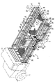
- the palletized cylinder distribution system of the present invention is shown in a perspective view in Figure 1.
- the system comprises a specially constructed truck 1, having a conventional cab 3 and wheels 5.
- the truck 1 does not have a conventional bed; instead, it bears a network of longitudinal beams 29 and transverse crossbeams 27.
- Mounted near the center of the network of beams and crossbeams is walkway 25.
- Walkway 25 comprises a metal grid, of sufficient strength to enable an operator of the system to walk thereon.
- the metal grid of walkway 25 defines a surface which is raised relative to the level of the network. While the invention is shown in connection with a truck, it is understood that any other type of vehicle can be employed, as long as it is capable of having the disclosed structure attached thereto.
- Truck 1 also comprises a conventional tailgate 7, which can be raised and lowered by conventional means, such as a hydraulic lift (not shown).
- Pallet 9 is shown resting on the network of beams 29 and crossbeams 27 of the truck. Gas cylinders 11 are shown disposed on the pallet, and are held within the pallet by strap 13. Only one pallet is shown in Figure 1, for the sake of clarity, but it is understood that, in the specific embodiment shown, ten pallets can be accommodated. Also, the invention can be used with less than a full load of pallets, because the pallets do not depend on adjacent pallets for anchoring. In the preferred embodiment, there are at least two pallets, and each pallet is preferably large enough to hold a plurality of cylinders. The precise dimensions of the walkway, and of the pallets themselves, are not critical and can be varied within the scope of the invention.
- the network of beams and crossbeams is provided with a plurality of dividers 49 which project upward from the network.
- the dividers 49 define spaces into which the pallets 9 can be inserted, and provide separation between adjacent pallets.
- Figure 1 shows four sets of dividers 49 disposed along the length of the network, thereby providing space for two rows of five pallets each. Other spacing arrangements can be used, depending on the truck size and the width of the pallets.
- the pallet 9 comprises a base portion 15, the base having a metal grid construction of a type similar to that of walkway 25.
- the metal grid of the base 15 must be of sufficient strength to support a plurality of cylinders 11, as shown.
- the mesh size of the grid of base 15 can be the same as that of the walkway, but it can also be of a different size.
- the base 15 of the pallet 9 is of sufficient height such that the surface on which the cylinders rest is substantially level with the surface of the walkway 25.
- Pallet 9 also comprises side plates 17 and end bars 19 which, together with strap 13, define a substantially rectangular enclosure for the cylinders 11.
- Walkway 25 defines a flange 31 which extends along substantially the entire length of the walkway.
- Flange 31 is adapted for engagement with front tab 39 of pallet 9, so as to hold the pallet in place during its transportation. The details of the engagement of the flange and the tab will be more clearly described below.
- Truck 1 is also provided with side rails 21, which are adapted to pivot around hinges 23.
- One of the side rails 23 is shown in its “ down” or open position, while the remaining side rails are shown in the “up” or closed position.
- Rail flange 43 is visible on the side rail which is “down”. Flange 43 is adapted for engagement with tabs on the rear side of the pallet; the details of the engagement will be more fully explained below.
- the vehicle does not have a conventional bed. Instead, the bases of the pallets and the surface of the walkway together define the bed of the vehicle.
- the invention eliminates the need for a heavy truck bed for supporting the pallets. The weight of the vehicle is thereby substantially reduced.
- the construction of the pallet 9 is shown in the perspective view of Figure 6.
- the figure shows an empty pallet, having base 15, side plates 17, and end bars 19. Strap 13 is shown hanging loose from the pallet.
- Each pallet is designed to accommodate two straps, which are fitted through strap slots 45, but only one strap is illustrated, for the sake of clarity.
- the base of the pallet is formed in part by I-beam 33 and two C-beams, only one of which is visible in the figure, the C-beam being designated by reference numeral 55.
- the side plates 17 and end bars 19 together define a substantially rectangular enclosure which is open at one side, for loading and unloading of individual cylinders from the pallet.
- the open side will be referred to throughout as the front of the pallet, and the side defined by end bars 19 is designated as the rear of the pallet_
- the construction of the base is sufficiently open to allow a fork member (not shown) of a conventional fork lift vehicle (also not shown) to be inserted under the pallet, so as to lift and transport the pallet.
- Front tabs 39 and rear tabs 41 (only one of which is visible in Figure 6) facilitate engagement of the pallet within the system, as will be described in detail later.
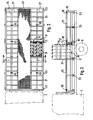
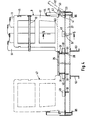
- Figure 2 Further details of the present invention are illustrated in the top view of Figure 2 and the side view of Figure 3.
- the metal grid of walkway 25 is shown in partially fragmentary form.
- the side rails 21 are all in the "up" position, and the single pallet 9 is also illustrated.
- Figure 2 also clearly shows dividers 49, defining the spaces into which the pallets can be loaded.
- Figure 3 shows the rear end of pallet 9, defined by end bars 19, the cylinders 11 also being visible. Also visible in Figure 3 are locking bars 35 for securing side rails 21 to posts 61.
- Figure 3 also provides a partial view of the I-beam 33 which is part of the base of the pallet 9.
- Figure 4 a cross-sectional view taken along the line 4-4 of Figure 2, shows the details of engagement of the pallets within the system.
- Figure 4 shows pallet 9, as well as another pallet 47, shown in phantom for the sake of illustration, the pallet 47 being of sub- : stantially identical construction to that of pallet 9.
- pallet 9 has a pair of front tabs 39 (only one of which is visible on pallet 9, in the view of Figure 4), the tabs being shaped so that the pallet can be engaged by flange 31 of walkway 25.
- the pallet also has a pair of rear tabs 41 (only one of which is visible in the figure) which are adapted for engagement with flange 43 of side rail 21.
- the side rail is also shown being pivoted around hinge 23, as indicated by the phantom drawing designated by reference numeral 37.
- the tilted version of flange 43 is indicated in phantom and identified by reference numeral 59.
- Dotted line 63 indicates the level of the top surface of the base 15 of the pallet, and it is therefore clear that the base of the pallet is substantially level with the surface of walkway 25.
- Figure 4 also shows corner piece 44 of side rail 21, which abuts the pallet when the side rail is in the "up" position. Also visible in Figure 4 are angles 51 which are used to join the sections of the longitudinal beams 29 to the crossbeams 27. Longitudinal support members 53, also visible in Figure 1, are also shown. The dividers 49 can be welded to the beams or the crossbeams, or can be attached by other means. Also visible in the figure are outer longitudinal beams 65.
- FIG. 5 Further details of construction of the pallet are illustrated in the cross-sectional view of Figure 5, taken along the line 5-5 of Figure 4.
- Base 15 of pallet 9 is clearly shown, together with I-beam 33 and C-beams 55.
- Figure 5 more clearly shows the pallet 9 resting within the space defined by adjacent dividers 49. Angles 51, crossbeams 27, and end beams 65 are also shown.
- flange 43 of the side rail does not extend along the entire length of the side rail, but is interrupted by posts 61 and by the vertical members of the side rails themselves.
- the construction of the pallet described above allows many different kinds of pallets to be used with the present system.
- the only requirements for the pallet are that the pallet fit within the space between the walkway and the side rail, and that the pallet have front and rear tabs to enable engagement and anchoring of the pallet as described above.
- the particular structure of the side walls of the pallet, or of the other features of its base, can be varied, while still being usable with this invention.
- the disclosed structure thus has an inherent flexibility not present with systems of the prior art.
- each pallet is first loaded with gas cylinders of the desired type.
- gas cylinders of the desired type As stated above, unless a certain customer has ordered a pallet load of cylinders of a particular mix of gases, it is preferable that each pallet be loaded with cylinders of only one kind of gas.
- the cylinders are secured in their pallets by tightening the one or two straps on each pallet.
- the pallets With the side rails 21 of the truck in the "down" position, the pallets are then loaded onto the crossbeam network by a conventional fork lift truck (not shown in the figures). The fork lift vehicle operator pushes the pallet forward, as far as the pallet will go, and the front tabs of the pallet will thereby engage the flange of the walkway.
- the side rails of the truck are raised and secured, at least one rear tab of each pallet will be automatically engaged, and the pallets are thereby firmly anchored on the truck.
- the cylinders can later be unloaded from the truck in two ways.
- the first alternative is to remove entire pallets of cylinders from the truck.
- the side rails are simply lowered, and a fork lift vehicle is used to remove the pallets from the sides of the truck, in the conventional manner.
- the second alternative which is used if it is necessary to retrieve only a small number of cylinders, or a small number of several different types cylinders, is as follows. First, the tailgate 7 of the truck is lowered.
- the operator of the system walks onto walkway 25, and walks to the pallet containing cylinders of the desired type of gas.
- An individual cylinder can be readily removed by unfastening the strap, and rolling a cylinder along the walkway, and onto the tailgate.
- each pallet contains only cylinders of one type of gas, it is not necessary to hunt for the desired cylinder.
- the cylinder nearest to the front end of the pallet may be taken and rolled along the walkway.
- the strap is then fastened again, securing the remaining cylinders in the pallet. The process is repeated for each different type of gas needed.
- the cylinders may be loaded or unloaded in complete pallets, or may be handled one at a time. In the latter case, no time is wasted in searching for a cylinder of the desired type of gas, because the walkway on the truck defines a center aisle, which makes all the cylinders readily accessible. No time is spent in moving some cylinders in order to gain access to others because the desired cylinder in each pallet is always the cylinder which is closest to the center aisle.
Landscapes
- Engineering & Computer Science (AREA)
- Transportation (AREA)
- Mechanical Engineering (AREA)
- Health & Medical Sciences (AREA)
- Public Health (AREA)
- Loading Or Unloading Of Vehicles (AREA)
- Filling Or Discharging Of Gas Storage Vessels (AREA)
Abstract
Description
- The present invention relates to the field of transportation and distribution of gas cylinders, in both large and small quantities.
- Pressurized cylinders have long been used for storage of specialized industrial gases. These cylinders are typically filled with gases such as oxygen, propane, acetylene, argon, nitrogen, or others. The cylinders are generally filled with the gas before delivery to a customer. After the gas is consumed, the cylinders are returned to the gas supply outlet, and replacement cylinders are delivered. The distribution of gases therefore involves repeated loading and unloading of filled or empty gas cylinders.
- Sometimes, a user of industrial gases requires gas in large quantities. At other times, as is the case for many small welding shops, only one or two cylinders will supply the needs of the shop for a reasonably long time. It is therefore necessary to handle small numbers of gas cylinders. The effort involved in handling such small quantities is magnified when, as often happens, the user of industrial gases requires small quantities of each of several different types of gas.
- The prior art has taught only one way of delivering loads of gas cylinders. A flatbed truck, i.e. a truck having a generally solid, flat surface, is loaded with a plurality of cylinders, the cylinders being tightly packed on the truck bed. Cylinders containing different types of gas are generally mixed together. The cylinders are then secured by a rope or chain extending across the bed of the truck. When a customer needs a type of gas which is found only in a cylinder which was packed onto the truck at the start of the loading process, all of the cylinders which were loaded subsequently must be moved, in order to gain access to the desired cylinder. After the desired cylinder has been removed, the cylinders which were moved to make way for the first cylinder must be then be returned to their previous positions.
- It is clear that the process described above is cumbersome and inefficient, especially when used to deliver small numbers of cylinders, and to deliver small quantities of each of several gases. Much of the cost of the gases is attributable to the labor required in delivering them. The prior art method described above is clearly very labor intensive.
- Few attempts have been made, in the prior art, to improve the process of transportation and distribution of gas cylinders. One such attempt is represented by U.S. Patent No. 4,295,431, which shows a paliet for holding pressurized gas cylinders. By holding the cylin- ders in pallets, more than one cylinder may be handled at once. The pallet includes three vertical side walls, and an open side for loading and unloading cylinders from the pallet. Another patent dealing with transportation and distribution of gas cylinders is U.S. Patent No. 3,993,344, which shows a plurality of pallets disposed on a flatbed truck.
- Other examples of the prior art include U.S. Patent No. 2,763,383, which shows apparatus for handling cylindrical containers, including gas containers; U.S. Patent No. 4,325,669, showing a pallet loading and unloading system; U.S. Patent No. 4,462,746, which shows apparatus for handling palletized loads; U.S. Patent No. 3,734,315, which discloses another means for transporting palletized loads; and U.S. Patent No. 4,165,806, showing another palletized distribution system.
- The present invention solves the problem of transporting and distributing varying quantities of gas cylinders, using a simple and economical structure, and requiring a minimum of labor. The invention provides a method and apparatus for delivering gas cylinders, either in entire pallet loads, or individually, without the expenditure of much time or effort.
- The palletized cylinder distribution system comprises a vehicle, such as a conventional truck, which is provided with a support means defined by a rectangular network of members and cross members. The network is skeletal in nature; the truck does not have its own flatbed. A walkway, comprising a heavy-gauge metal grid, is mounted on the network, and extends substantially along its length. The walkway divides the network into at least two regions. Pallets capable of holding gas cylinders are disposed in rows in the regions adjacent the walkway. Side rails are pivotably mounted to the sides of the network, and can be raised to help secure the paliets previously loaded, or lowered, to allow access to the paliets from the side of the truck. The paliets have base portions which, together with the surface of the walkway, collectively define the bed of the truck. The base portions of the pallets have tabs, located at the corners of the base portions, the tabs being adapted for engagement with flanges on the side rails and on the walkway, as will be described below.
- The walkway includes a longitudinal flange for engaging the tabs on the base of the pallet, when the pallet is pushed onto the truck and towards the walkway. The flanges on the side rails are of a construction similar to that of the flange on the walkway, so that when the side rails are raised, at least some of their flanges engage the tabs on the other side of the pallet base. Each pallet is held securely in place by at least three of its four tabs. Engagement of the tabs thus insures that the pallets will be virtually immobile while the vehicle is in motion.
- According to the method of the present invention, a small number of gas cylinders (the number can be as small as one), of one type or of several different types of gas, are quickly loaded or unloaded. Each pallet is used to store a plurality of cylinders having a different type of gas. When a particular cylinder is needed, the operator walks along the walkway to the pallet which holds the cylinders of the desired gas. One or more cylinders are then removed and rolled along the walkway, and taken from the truck. Single or multiple cylinders can be loaded by reversing the above procedure.
- If an entire pallet of cylinders is to be loaded or unloaded, the pallet can be handled as a unit, by a conventional fork lift truck. The pallet is designed to allow the fork member of a fork lift vehicle to pass under the surface of the pallet base, and to lift the pallet. The pallet is then loaded or unloaded from the side of the truck. Special pallet loads, comprising a predetermined assortment of gas cylinders, may be prepared in advance, so that the unloading of cylinders for customers having special needs can be further expedited.
- It is therefore an object of the present invention to provide a palletized cylinder distribution system, the system being adapted for easy loading and unloading of small or large quantities of gas cylinders.
- It is another object to provide a system as described above, the system being capable of handling single cylinders as well as entire pallet loads of cylinders with a minimum of time and effort.
- It is another object of the invention to provide a system as described above, wherein the system maximizes access to the various cylinders by the operator of the system.
- It is another object of the invention to provide a system as described above, wherein the pallets are securely held on a vehicle, while being transported.
- It is another object of the invention to provide a system as described above, wherein the system includes a truck having a bed which is defined in part by the bases of the pallets.
- It is another object of the invention to provide a system as described above, wherein the system accommodates different kinds of pallets.
- It is another object of the invention to provide a pallet for gas cylinders, the pallet being capable of being securely mounted in a variety of pallet transportation systems.
- It is another object to provide a method of loading and unloading gas cylinders, the method being suitable for either large or small quantities of cylinders.
- Other objects and advantages of the invention will be apparent to those skilled in the art, from a reading of the following brief description of the drawings, the detailed description of the invention, and the appended claims.
-
- Figure 1 is a perspective view illustrating the apparatus of the present invention, with one pallet of cylinders loaded on the truck.
- Figure 2 is a partially fragmentary top view of the truck shown in Figure 1.
- Figure 3 is a partially fragmentary side view of the truck of Figures 1 and 2.
- Figure 4 is a cross-sectional view, taken along the line 4-4 of Figure 2.
- Figure 5 is a cross-sectional view, taken along the line 5-5 of Figure 4.
- Figure 6 is a perspective view showing an empty pallet, suitable for use with the present invention.
- The palletized cylinder distribution system of the present invention is shown in a perspective view in Figure 1. The system comprises a specially constructed
truck 1, having a conventional cab 3 andwheels 5. Thetruck 1 does not have a conventional bed; instead, it bears a network oflongitudinal beams 29 andtransverse crossbeams 27. Mounted near the center of the network of beams and crossbeams iswalkway 25.Walkway 25 comprises a metal grid, of sufficient strength to enable an operator of the system to walk thereon. The metal grid ofwalkway 25 defines a surface which is raised relative to the level of the network. While the invention is shown in connection with a truck, it is understood that any other type of vehicle can be employed, as long as it is capable of having the disclosed structure attached thereto. -
Truck 1 also comprises a conventional tailgate 7, which can be raised and lowered by conventional means, such as a hydraulic lift (not shown). -
Pallet 9 is shown resting on the network ofbeams 29 andcrossbeams 27 of the truck.Gas cylinders 11 are shown disposed on the pallet, and are held within the pallet bystrap 13. Only one pallet is shown in Figure 1, for the sake of clarity, but it is understood that, in the specific embodiment shown, ten pallets can be accommodated. Also, the invention can be used with less than a full load of pallets, because the pallets do not depend on adjacent pallets for anchoring. In the preferred embodiment, there are at least two pallets, and each pallet is preferably large enough to hold a plurality of cylinders. The precise dimensions of the walkway, and of the pallets themselves, are not critical and can be varied within the scope of the invention. - The network of beams and crossbeams is provided with a plurality of
dividers 49 which project upward from the network. Thedividers 49 define spaces into which thepallets 9 can be inserted, and provide separation between adjacent pallets. Figure 1 shows four sets ofdividers 49 disposed along the length of the network, thereby providing space for two rows of five pallets each. Other spacing arrangements can be used, depending on the truck size and the width of the pallets. - The
pallet 9 comprises abase portion 15, the base having a metal grid construction of a type similar to that ofwalkway 25. The metal grid of the base 15 must be of sufficient strength to support a plurality ofcylinders 11, as shown. The mesh size of the grid ofbase 15 can be the same as that of the walkway, but it can also be of a different size. Thebase 15 of thepallet 9 is of sufficient height such that the surface on which the cylinders rest is substantially level with the surface of thewalkway 25. -
Pallet 9 also comprisesside plates 17 and end bars 19 which, together withstrap 13, define a substantially rectangular enclosure for thecylinders 11. -
Walkway 25 defines aflange 31 which extends along substantially the entire length of the walkway.Flange 31 is adapted for engagement withfront tab 39 ofpallet 9, so as to hold the pallet in place during its transportation. The details of the engagement of the flange and the tab will be more clearly described below. -
Truck 1 is also provided withside rails 21, which are adapted to pivot around hinges 23. One of the side rails 23 is shown in its "down" or open position, while the remaining side rails are shown in the "up" or closed position.Rail flange 43 is visible on the side rail which is "down".Flange 43 is adapted for engagement with tabs on the rear side of the pallet; the details of the engagement will be more fully explained below. - Although the particular type of vehicle used with the present invention is not critical, it is a feature of the invention that the vehicle does not have a conventional bed. Instead, the bases of the pallets and the surface of the walkway together define the bed of the vehicle. Thus, the invention eliminates the need for a heavy truck bed for supporting the pallets. The weight of the vehicle is thereby substantially reduced.
- The construction of the
pallet 9 is shown in the perspective view of Figure 6. The figure shows an empty pallet, havingbase 15,side plates 17, and end bars 19.Strap 13 is shown hanging loose from the pallet. Each pallet is designed to accommodate two straps, which are fitted throughstrap slots 45, but only one strap is illustrated, for the sake of clarity. The base of the pallet is formed in part by I-beam 33 and two C-beams, only one of which is visible in the figure, the C-beam being designated byreference numeral 55. Theside plates 17 and end bars 19 together define a substantially rectangular enclosure which is open at one side, for loading and unloading of individual cylinders from the pallet. The open side will be referred to throughout as the front of the pallet, and the side defined byend bars 19 is designated as the rear of the pallet_ The construction of the base is sufficiently open to allow a fork member (not shown) of a conventional fork lift vehicle (also not shown) to be inserted under the pallet, so as to lift and transport the pallet. -
Front tabs 39 and rear tabs 41 (only one of which is visible in Figure 6) facilitate engagement of the pallet within the system, as will be described in detail later. - Further details of the present invention are illustrated in the top view of Figure 2 and the side view of Figure 3. In Figure 2, the metal grid of
walkway 25 is shown in partially fragmentary form. The side rails 21 are all in the "up" position, and thesingle pallet 9 is also illustrated. Figure 2 also clearly showsdividers 49, defining the spaces into which the pallets can be loaded. Figure 3 shows the rear end ofpallet 9, defined byend bars 19, thecylinders 11 also being visible. Also visible in Figure 3 are lockingbars 35 for securingside rails 21 toposts 61. Figure 3 also provides a partial view of the I-beam 33 which is part of the base of thepallet 9. - Figure 4, a cross-sectional view taken along the line 4-4 of Figure 2, shows the details of engagement of the pallets within the system. Figure 4 shows
pallet 9, as well as anotherpallet 47, shown in phantom for the sake of illustration, thepallet 47 being of sub- : stantially identical construction to that ofpallet 9. As shown in Figure 4,pallet 9 has a pair of front tabs 39 (only one of which is visible onpallet 9, in the view of Figure 4), the tabs being shaped so that the pallet can be engaged byflange 31 ofwalkway 25. - The pallet also has a pair of rear tabs 41 (only one of which is visible in the figure) which are adapted for engagement with
flange 43 ofside rail 21. The side rail is also shown being pivoted aroundhinge 23, as indicated by the phantom drawing designated byreference numeral 37. The tilted version offlange 43 is indicated in phantom and identified by reference numeral 59.Dotted line 63 indicates the level of the top surface of thebase 15 of the pallet, and it is therefore clear that the base of the pallet is substantially level with the surface ofwalkway 25. - Figure 4 also shows
corner piece 44 ofside rail 21, which abuts the pallet when the side rail is in the "up" position. Also visible in Figure 4 areangles 51 which are used to join the sections of thelongitudinal beams 29 to thecrossbeams 27.Longitudinal support members 53, also visible in Figure 1, are also shown. Thedividers 49 can be welded to the beams or the crossbeams, or can be attached by other means. Also visible in the figure are outerlongitudinal beams 65. - Further details of construction of the pallet are illustrated in the cross-sectional view of Figure 5, taken along the line 5-5 of Figure 4.
Base 15 ofpallet 9 is clearly shown, together with I-beam 33 and C-beams 55. Also visible is aside rail 21, and theflange 43 of the rail, in engagement with the rear tab 41 (not directly shown in Fig. 5) of the pallet. Figure 5 more clearly shows thepallet 9 resting within the space defined byadjacent dividers 49.Angles 51,crossbeams 27, and endbeams 65 are also shown. - As can best be seen in Figure 1, with reference to the
side rail 21 which is in the "down" position,flange 43 of the side rail does not extend along the entire length of the side rail, but is interrupted byposts 61 and by the vertical members of the side rails themselves. Thus, it is possible that not everyrear tab 41 of eachpallet 9 will be engaged by aflange 43 of a side rail. However, at least one of the rear tabs will, in general, be so engaged. Since both of thefront tabs 39 will always be engaged byflange 31 ofwalkway 25, the latter flange extending along substantially the entire length of the walkway, at least three of the four tabs on each pallet will be engaged. Engagement by three of four tabs is sufficient to hold the pallet securely on the truck. - The construction of the pallet described above allows many different kinds of pallets to be used with the present system. The only requirements for the pallet are that the pallet fit within the space between the walkway and the side rail, and that the pallet have front and rear tabs to enable engagement and anchoring of the pallet as described above. The particular structure of the side walls of the pallet, or of the other features of its base, can be varied, while still being usable with this invention. The disclosed structure thus has an inherent flexibility not present with systems of the prior art.
- The operation of the invention will now be described. In the initial loading phase, each pallet is first loaded with gas cylinders of the desired type. As stated above, unless a certain customer has ordered a pallet load of cylinders of a particular mix of gases, it is preferable that each pallet be loaded with cylinders of only one kind of gas. The cylinders are secured in their pallets by tightening the one or two straps on each pallet. With the side rails 21 of the truck in the "down" position, the pallets are then loaded onto the crossbeam network by a conventional fork lift truck (not shown in the figures). The fork lift vehicle operator pushes the pallet forward, as far as the pallet will go, and the front tabs of the pallet will thereby engage the flange of the walkway. When the side rails of the truck are raised and secured, at least one rear tab of each pallet will be automatically engaged, and the pallets are thereby firmly anchored on the truck.
- The cylinders can later be unloaded from the truck in two ways. The first alternative is to remove entire pallets of cylinders from the truck. The side rails are simply lowered, and a fork lift vehicle is used to remove the pallets from the sides of the truck, in the conventional manner. The second alternative, which is used if it is necessary to retrieve only a small number of cylinders, or a small number of several different types cylinders, is as follows. First, the tailgate 7 of the truck is lowered. The operator of the system walks onto
walkway 25, and walks to the pallet containing cylinders of the desired type of gas. An individual cylinder can be readily removed by unfastening the strap, and rolling a cylinder along the walkway, and onto the tailgate. Because each pallet contains only cylinders of one type of gas, it is not necessary to hunt for the desired cylinder. The cylinder nearest to the front end of the pallet may be taken and rolled along the walkway. The strap is then fastened again, securing the remaining cylinders in the pallet. The process is repeated for each different type of gas needed. - Use of the system of the present invention therefore saves considerable time in the loading and unloading of cylinders. The cylinders may be loaded or unloaded in complete pallets, or may be handled one at a time. In the latter case, no time is wasted in searching for a cylinder of the desired type of gas, because the walkway on the truck defines a center aisle, which makes all the cylinders readily accessible. No time is spent in moving some cylinders in order to gain access to others because the desired cylinder in each pallet is always the cylinder which is closest to the center aisle.
- The objects of the invention are clearly fulfilled by the above disclosure. It is understood, however, that the invention can be modified in various ways within the scope of the disclosure. The particular number of pallets, the mesh size of the network of beams and crossbeams, and the shape of the side plates or the end bars of the pallets are examples of features which may be changed. The particular construction of the side rails and the tailgate of the truck could also be modified. The invention is therefore not limited to the precise embodiments disclosed. Variations such as those discussed above, and others, are to be deemed within the spirit and scope of the following claims.
Claims (23)
Applications Claiming Priority (2)
| Application Number | Priority Date | Filing Date | Title |
|---|---|---|---|
| US06/717,852 US4642007A (en) | 1985-03-29 | 1985-03-29 | Palletized cylinder distribution system |
| US717852 | 1985-03-29 |
Publications (2)
| Publication Number | Publication Date |
|---|---|
| EP0203303A2 true EP0203303A2 (en) | 1986-12-03 |
| EP0203303A3 EP0203303A3 (en) | 1987-08-19 |
Family
ID=24883752
Family Applications (1)
| Application Number | Title | Priority Date | Filing Date |
|---|---|---|---|
| EP86104033A Withdrawn EP0203303A3 (en) | 1985-03-29 | 1986-03-24 | Palletized cylinder distribution system |
Country Status (2)
| Country | Link |
|---|---|
| US (1) | US4642007A (en) |
| EP (1) | EP0203303A3 (en) |
Cited By (3)
| Publication number | Priority date | Publication date | Assignee | Title |
|---|---|---|---|---|
| US5154556A (en) * | 1990-08-30 | 1992-10-13 | Camco International Inc. | Retention device for metal cylindrical containers |
| CN104044498A (en) * | 2014-06-18 | 2014-09-17 | 国网四川省电力公司成都市新都供电分公司 | Distribution network recovery vehicle |
| EP4775449A1 (en) | 2025-01-09 | 2026-07-15 | L'air Liquide, Societe Anonyme Pour L'etude Et L'exploitation Des Procedes Georges Claude | Platform for gas transportation |
Families Citing this family (28)
| Publication number | Priority date | Publication date | Assignee | Title |
|---|---|---|---|---|
| US5022809A (en) * | 1990-02-07 | 1991-06-11 | Solite Corporation | Truck for alternately handling bulk and palletized cargo |
| US5277536A (en) * | 1991-12-02 | 1994-01-11 | Baldwin Kevin L | Co-mingled material recovery apparatus for recycling |
| US5618138A (en) * | 1994-04-08 | 1997-04-08 | Mathey/Leland International, Ltd. | Truck pallet locking device |
| US5573360A (en) * | 1995-03-16 | 1996-11-12 | Bennett; Richard C. | Pallet latching mechanism |
| US6109845A (en) * | 1998-08-21 | 2000-08-29 | Blue Star Trailer Rentals, Inc. | Trailer recovery vehicle |
| US6067913A (en) * | 1998-10-30 | 2000-05-30 | Bennett; Richard C. | Stackable pallet system for transporting gas containers |
| US6183042B1 (en) * | 1998-12-21 | 2001-02-06 | Albert W. Unrath | Mobile apparatus for securely retrieving and placing markers on a surface and method therefor |
| AU3211400A (en) * | 1999-01-20 | 2000-08-07 | Coca-Cola Enterprises, Inc. | Beverage distribution system and method of its manufacture and operation |
| US6299184B1 (en) | 1999-01-20 | 2001-10-09 | Magline, Inc. | Transport cart system and method of its manufacture and operation |
| NL1016555C2 (en) * | 2000-11-07 | 2002-05-14 | Hoek Loos Bv | Container for gas cylinders or the like and method for manufacturing them. |
| US6685404B2 (en) | 2002-03-22 | 2004-02-03 | Aga Gas, Inc. | Method, system, and device for transporting gas cylinders |
| US6916142B2 (en) * | 2002-07-19 | 2005-07-12 | Deere & Company | Utility vehicles |
| US7275902B1 (en) | 2004-04-29 | 2007-10-02 | Welding Company Of America | Gas cylinder delivery system |
| FR2873666B1 (en) * | 2004-07-29 | 2008-07-18 | Butagaz Snc | METHOD AND DEVICES FOR HANDLING AND DISTRIBUTING BOTTLES OF LIQUEFIED PETROLEUM GASES |
| FR2889511B1 (en) * | 2005-08-05 | 2008-10-31 | Jacques Gonzales | DEVICE FOR TRANSPORTING BOMBON OR GAS BOTTLE |
| US7524159B2 (en) * | 2006-04-10 | 2009-04-28 | U Box It Inc. | Method of receiving and transporting solid waste |
| US20090035106A1 (en) * | 2006-04-10 | 2009-02-05 | U Box It, Inc. | Method of receiving and transporting solid waste |
| BR112013029664B1 (en) * | 2011-05-17 | 2022-01-04 | Infilco Degremont. Inc | FLUID TREATMENT SYSTEM |
| US20130142612A1 (en) * | 2011-12-01 | 2013-06-06 | Michael G. Monsive, Jr. | Wheel-less portable security system and deployment thereof |
| FR3010768B1 (en) * | 2013-09-19 | 2017-01-13 | Air Liquide | DEVICE FOR SUPPLYING GAS |
| FR3020442B1 (en) * | 2014-04-24 | 2017-02-17 | Air Liquide | DEVICE FOR SUPPLYING GAS |
| US10817925B2 (en) * | 2014-10-08 | 2020-10-27 | Ratermann Manufacturing, Inc. | Gas cylinder inventory signaling apparatus and method |
| US10801169B2 (en) * | 2015-06-29 | 2020-10-13 | Royal Truck & Equipment, Inc | Truck safety modules for assisting workpersons to place and retrieve traffic delineators |
| US10556545B2 (en) | 2015-06-29 | 2020-02-11 | Royal Truck & Equipment, Inc. | Over-cab rack for traffic delineators |
| US10319227B2 (en) | 2015-06-29 | 2019-06-11 | Royal Truck & Equipment, Inc. | Roadway work area safety truck |
| US11008717B2 (en) | 2015-06-29 | 2021-05-18 | Royal Truck & Equipment, Inc. | Safety truck attachments, and methods of safety truck use |
| TN2016000523A1 (en) * | 2016-11-22 | 2018-04-04 | Abdelfatiah Daoud | An industrial gas basket allowing unloading packaging and distribution without trolley. |
| CN108278485A (en) * | 2018-02-06 | 2018-07-13 | 衡阳泰豪通信车辆有限公司 | A kind of pallet for transporting gas cylinder |
Family Cites Families (15)
| Publication number | Priority date | Publication date | Assignee | Title |
|---|---|---|---|---|
| US1252810A (en) * | 1915-04-21 | 1918-01-08 | River And Rail Transp Company | Interchangeable-unit car. |
| US1470266A (en) * | 1920-02-16 | 1923-10-09 | Kirchner Henry William | Interchangeable-unit carrier |
| US2763383A (en) * | 1955-08-15 | 1956-09-18 | Diamond Alkali Co | Self-loading or unloading vehicle for cylindrical containers |
| US3059592A (en) * | 1956-09-06 | 1962-10-23 | Fairchild Stratos Corp | Cargo-handling system |
| US3159111A (en) * | 1962-05-14 | 1964-12-01 | Puilman Inc | Container attachment device for railway cars |
| US3451573A (en) * | 1967-07-03 | 1969-06-24 | Pacific Oxygen Co | Transporting system |
| US3734315A (en) * | 1970-07-08 | 1973-05-22 | Palmer Shile Co | Means for transporting palletized loads |
| US3993344A (en) * | 1973-07-02 | 1976-11-23 | Bennett Richard C | Transporting system |
| US3934924A (en) * | 1974-10-24 | 1976-01-27 | Joseph Diliberti | Camping apparatus for van-type vehicle |
| US4165806A (en) * | 1976-07-26 | 1979-08-28 | Bud Antle, Inc. | Palletizing system for produce cartons and the like |
| US4231695A (en) * | 1978-07-10 | 1980-11-04 | Weston Sr Robert M | Cargo loading and unloading apparatus for trucks |
| US4295431A (en) * | 1979-11-23 | 1981-10-20 | Aga Ab | Pallet for pressurized gas cylinders |
| DE2947315C2 (en) * | 1979-11-23 | 1981-12-24 | Wilhelm 8059 Reisen Kick | Quick fastening device for manually releasable fixing of pieces of furniture in the transport space of a transport vehicle |
| US4325669A (en) * | 1980-08-04 | 1982-04-20 | George Schafer | Pallet loading and unloading method |
| US4462746A (en) * | 1982-11-22 | 1984-07-31 | Smetco, Inc. | Pallet handling apparatus and method |
-
1985
- 1985-03-29 US US06/717,852 patent/US4642007A/en not_active Expired - Fee Related
-
1986
- 1986-03-24 EP EP86104033A patent/EP0203303A3/en not_active Withdrawn
Cited By (4)
| Publication number | Priority date | Publication date | Assignee | Title |
|---|---|---|---|---|
| US5154556A (en) * | 1990-08-30 | 1992-10-13 | Camco International Inc. | Retention device for metal cylindrical containers |
| CN104044498A (en) * | 2014-06-18 | 2014-09-17 | 国网四川省电力公司成都市新都供电分公司 | Distribution network recovery vehicle |
| CN104044498B (en) * | 2014-06-18 | 2016-02-10 | 国网四川省电力公司成都市新都供电分公司 | A kind of distribution breakdown van |
| EP4775449A1 (en) | 2025-01-09 | 2026-07-15 | L'air Liquide, Societe Anonyme Pour L'etude Et L'exploitation Des Procedes Georges Claude | Platform for gas transportation |
Also Published As
| Publication number | Publication date |
|---|---|
| EP0203303A3 (en) | 1987-08-19 |
| US4642007A (en) | 1987-02-10 |
Similar Documents
| Publication | Publication Date | Title |
|---|---|---|
| US4642007A (en) | Palletized cylinder distribution system | |
| US6685404B2 (en) | Method, system, and device for transporting gas cylinders | |
| US11046371B2 (en) | System for conveying and stowing elongated material | |
| US4344368A (en) | Universal pallet | |
| US5344266A (en) | Fully adjustable storage device for loading and transporting vehicles in containers | |
| US4834000A (en) | Load and roll pallet | |
| US3626872A (en) | Tie-down pallet | |
| US5154556A (en) | Retention device for metal cylindrical containers | |
| US4799840A (en) | Drum-restraining device | |
| US20110155740A1 (en) | Modular carrier apparatuses and methods thererfor | |
| US6135706A (en) | Method of manufacturing packing and transporting computers | |
| US10934053B1 (en) | Adjustable pallet rack | |
| CA2232820A1 (en) | Modular storage system for stacking cylindrical loads | |
| US3451573A (en) | Transporting system | |
| US6386807B1 (en) | Stackable trailers | |
| US4952114A (en) | Device for transporting adjusting frames for scaffolding | |
| US3481627A (en) | Cargo fixture for trailers | |
| US10569811B2 (en) | Modular transportation and storage system | |
| US6067913A (en) | Stackable pallet system for transporting gas containers | |
| JPH09118236A (en) | Method and apparatus for conveying thin rectangular objects | |
| US3297175A (en) | Bulkhead structure | |
| US6240854B1 (en) | Palletizing system for items on wheels | |
| JP3376404B2 (en) | Method of transporting and storing goods such as tires using a comb-shaped lattice-shaped holder, and a container for transport and storage | |
| US4878605A (en) | Load carrying apparatus | |
| EP0105754A2 (en) | A rack and a method for storing wheeled container chassis |
Legal Events
| Date | Code | Title | Description |
|---|---|---|---|
| PUAI | Public reference made under article 153(3) epc to a published international application that has entered the european phase |
Free format text: ORIGINAL CODE: 0009012 |
|
| AK | Designated contracting states |
Kind code of ref document: A2 Designated state(s): DE FR |
|
| PUAL | Search report despatched |
Free format text: ORIGINAL CODE: 0009013 |
|
| AK | Designated contracting states |
Kind code of ref document: A3 Designated state(s): DE FR |
|
| STAA | Information on the status of an ep patent application or granted ep patent |
Free format text: STATUS: THE APPLICATION IS DEEMED TO BE WITHDRAWN |
|
| 18D | Application deemed to be withdrawn |
Effective date: 19880222 |
|
| RIN1 | Information on inventor provided before grant (corrected) |
Inventor name: INGHAM, VERNON R. Inventor name: MARSHALL, MICHAEL B. |