EP0201223A1 - Weatherstrip - Google Patents
Weatherstrip Download PDFInfo
- Publication number
- EP0201223A1 EP0201223A1 EP86302777A EP86302777A EP0201223A1 EP 0201223 A1 EP0201223 A1 EP 0201223A1 EP 86302777 A EP86302777 A EP 86302777A EP 86302777 A EP86302777 A EP 86302777A EP 0201223 A1 EP0201223 A1 EP 0201223A1
- Authority
- EP
- European Patent Office
- Prior art keywords
- strip
- weatherstrip
- channel
- ribs
- retaining portion
- Prior art date
- Legal status (The legal status is an assumption and is not a legal conclusion. Google has not performed a legal analysis and makes no representation as to the accuracy of the status listed.)
- Granted
Links
Images


Classifications
-
- B—PERFORMING OPERATIONS; TRANSPORTING
- B60—VEHICLES IN GENERAL
- B60J—WINDOWS, WINDSCREENS, NON-FIXED ROOFS, DOORS, OR SIMILAR DEVICES FOR VEHICLES; REMOVABLE EXTERNAL PROTECTIVE COVERINGS SPECIALLY ADAPTED FOR VEHICLES
- B60J10/00—Sealing arrangements
- B60J10/20—Sealing arrangements characterised by the shape
- B60J10/24—Sealing arrangements characterised by the shape having tubular parts
- B60J10/242—Sealing arrangements characterised by the shape having tubular parts with vent holes
-
- B—PERFORMING OPERATIONS; TRANSPORTING
- B60—VEHICLES IN GENERAL
- B60J—WINDOWS, WINDSCREENS, NON-FIXED ROOFS, DOORS, OR SIMILAR DEVICES FOR VEHICLES; REMOVABLE EXTERNAL PROTECTIVE COVERINGS SPECIALLY ADAPTED FOR VEHICLES
- B60J10/00—Sealing arrangements
- B60J10/30—Sealing arrangements characterised by the fastening means
-
- B—PERFORMING OPERATIONS; TRANSPORTING
- B60—VEHICLES IN GENERAL
- B60J—WINDOWS, WINDSCREENS, NON-FIXED ROOFS, DOORS, OR SIMILAR DEVICES FOR VEHICLES; REMOVABLE EXTERNAL PROTECTIVE COVERINGS SPECIALLY ADAPTED FOR VEHICLES
- B60J10/00—Sealing arrangements
- B60J10/80—Sealing arrangements specially adapted for opening panels, e.g. doors
Definitions
- This invention relates to a weatherstrip such as is used, for example, around the edges of the doors and/or boot lids of motor vehicles to seal the doors or boot lid to the rest of the vehicle when the door is closed.
- Attachment of the weatherstrip to the appropriate metal panel is conventionally done using either adhesive to glue a part of the weatherstrip to the host panel, or by incorporating in the weatherstrip a metal strip which can be clinched around the edge of the host panel.
- the edge of the host panel must of course be formed in such a way as to provide an adequate mounting surface for the weatherstrip. Two particular formations are common. Firstly, where the strip is to be glued in place, a channel may be formed at the edge of the panel to accept a strip retaining portion which is actually directly glued to the panel. In a second construction, the edge of the host panel provides a relatively thin, flat rim over which a metal clip retainer incorporated in the weatherstrip can be clinched.
- a weatherstrip for use on a component which has a channel with a retaining lip for receiving the strip, the strip having a sealing bead and a strip retaining portion, the strip retaining portion having a body and at least one primary and a plurality of secondary flexible ribs all of which extend laterally from the body, the secondary ribs having a greater lateral extent than the primary ribs, all the ribs being adapted to fold back towards the body to allow the strip retaining portion to enter the channel and then to spring out, with the primary rib engaging under the retaining lip and the secondary ribs contacting the internal side walls of the channel.
- the secondary ribs when in an unstressed condition, extend generally towards the mouth of the channel and, when the strip is in place, are deformed against the side walls of the channel. These secondary ribs then assist in preventing the strip from being pulled out of the channel because they will buckle between the rib tip and the rib root, and will thus increase the pressure exerted against the side of the channel.
- the strip retaining portion preferably also includes tertiary flexible ribs which extend from the body of the strip retaining portion to contact the base of the channel in the host panel. These tertiary ribs thus ensure that the primary rib is correctly positioned relative to the shoulder of the channel.
- the weatherstrip is preferably made in a single material, although the sealing bead may be formed from foamed material whilst the strip retaining portion is formed from solid material.
- the weatherstrip can however be formed in a single moulding process, using known techniques which allow the material in one part of the strip to be of a different composition from that in another part of the strip.
- a suitable material for the strip is EPDM rubber.
- Production of a host panel with a channel around its periphery is cheaper than production of a corresponding host panel with a fully clinched edge.
- the strip comprises a sealing bead 10 which is generally circular in form and hollow. Drain holes, air escape holes and mould core removal holes 12 are provided in various places around the bead periphery.
- the bead is formed from EPDM rubber foam.
- the bead 10 is connected to a strip retaining portion 14 which has a Christmas tree formation.
- the strip retaining portion is formed of solid EPDM rubber, and the junction between the solid and foamed rubber regions can be seen at 16 and 18.
- the complete strip can however be formed in one moulding process, using known techniques.
- the retaining portion 14 has one primary rib 20, three secondary ribs 22 and two tertiary ribs 24.
- the primary and secondary ribs are all directed laterally outwardly and towards the bead 10.
- a host panel is generally indicated at 26 and comprises an inner panel 28 and an outer panel 30. Only the edges of these panels are shown, but it can be seen that they co-operate to form a channel 32 which has a mouth 34 narrower than the width of the interior of the channel. The mouth 34 is narrowed by the provision of a retaining lip 36 which is part of the outer panel 30.
- the inner and outer panels 28 and 30 will be secured together by spot welding between the parallel panel surfaces in the region 38.
- the strip itself also has an exterior lip 40.
- Figure 3 shows how the strip is assembled to the channel 32.
- the mouth of the opening 34 has a width dimension X.
- the relative sizes of the strip retaining portion body 14 and the ribs 20 and 22 are such that the ribs can fold inwards on insertion to achieve a dimension less than or equal to dimension X, and this can be accomplished without the use of any tools simply by pushing the strip in through the mouth 34.
- the ribs fold up as shown in Figure 3.
- Insertion of the strip is thus easily done by simply pressing the strip into place. No additional materials are required and no tools are needed.
- the strip can be inserted without requiring any special skill or any particular effort.
- the ribs Once the ribs have passed through the opening 34, they will expand outwards again into contact with the walls of the channel as can be seen in Figure 2.
- the primary rib 20 is normally unstressed. No additional adhesive or any other extraneous material is needed to hold the weatherstrip in place.
- the tertiary ribs 24 provide flexibility for the strip to fit properly into the channel where the depth of the channel varies, for example at body feature lines on a motor vehicle body. They also help to ensure that the primary rib 20 is always enaged with the lip 36, and, in conjunction with all the other ribs, holds the weatherstrip in a stable condition within the host panel.
- the lip 40 fits against the outside of the host panel in the manner shown.
Landscapes
- Engineering & Computer Science (AREA)
- Mechanical Engineering (AREA)
- Seal Device For Vehicle (AREA)
- Vehicle Waterproofing, Decoration, And Sanitation Devices (AREA)
Abstract
Description
- This invention relates to a weatherstrip such as is used, for example, around the edges of the doors and/or boot lids of motor vehicles to seal the doors or boot lid to the rest of the vehicle when the door is closed.
- Attachment of the weatherstrip to the appropriate metal panel (hereinafter called the host panel) is conventionally done using either adhesive to glue a part of the weatherstrip to the host panel, or by incorporating in the weatherstrip a metal strip which can be clinched around the edge of the host panel.
- Neither of these methods is entirely satisfactory. With both methods there is a tendency for the strip to separate from the host panel under adverse conditions. Furthermore, a strip attached using adhesive often has a poor appearance. Both methods are laborious to fit and involve additional cost in respect of the adhesive or metal insert.
- The edge of the host panel must of course be formed in such a way as to provide an adequate mounting surface for the weatherstrip. Two particular formations are common. Firstly, where the strip is to be glued in place, a channel may be formed at the edge of the panel to accept a strip retaining portion which is actually directly glued to the panel. In a second construction, the edge of the host panel provides a relatively thin, flat rim over which a metal clip retainer incorporated in the weatherstrip can be clinched.
- According to the present invention, there is provided a weatherstrip for use on a component which has a channel with a retaining lip for receiving the strip, the strip having a sealing bead and a strip retaining portion, the strip retaining portion having a body and at least one primary and a plurality of secondary flexible ribs all of which extend laterally from the body, the secondary ribs having a greater lateral extent than the primary ribs, all the ribs being adapted to fold back towards the body to allow the strip retaining portion to enter the channel and then to spring out, with the primary rib engaging under the retaining lip and the secondary ribs contacting the internal side walls of the channel.
- With such a weatherstrip, no adhesive or metal insert is required to be associated with the strip. Assembly of the strip to the host panel is carried out simply by pushing the strip retaining portion into the channel where it automatically seats itself. Any tendency for the strip to pull out of the channel is resisted firstly by the primary rib which engages under the retaining lip.
- Preferably the secondary ribs, when in an unstressed condition, extend generally towards the mouth of the channel and, when the strip is in place, are deformed against the side walls of the channel. These secondary ribs then assist in preventing the strip from being pulled out of the channel because they will buckle between the rib tip and the rib root, and will thus increase the pressure exerted against the side of the channel.
- The strip retaining portion preferably also includes tertiary flexible ribs which extend from the body of the strip retaining portion to contact the base of the channel in the host panel. These tertiary ribs thus ensure that the primary rib is correctly positioned relative to the shoulder of the channel.
- The weatherstrip is preferably made in a single material, although the sealing bead may be formed from foamed material whilst the strip retaining portion is formed from solid material. The weatherstrip can however be formed in a single moulding process, using known techniques which allow the material in one part of the strip to be of a different composition from that in another part of the strip.
- In a preferred embodiment, there is one primary rib on one side of the body of the retaining portion, one secondary rib on the same side and two secondary ribs on the opposite side of the strip retaining portion body. Two tertiary ribs can be provided.
- A suitable material for the strip is EPDM rubber.
- Production of a host panel with a channel around its periphery is cheaper than production of a corresponding host panel with a fully clinched edge.
- The invention will now be described further, by way of example, with reference to the accompanying drawings in which:
- Figure 1 shows a cross section through a weatherstrip according to the invention, with the weatherstrip being shown in a relaxed condition but against the background of a suitable host panel;
- Figure 2 shows the position that the ribs of the strip take up during fitting of the strip to the host panel;
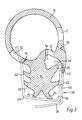
- Figure 3 shows the weatherstrip of Figure 1 in place 25 on a host panel; and
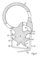
- Figure 4 shows what happens on attempted pull-out of the strip.
- Although the drawings all show a cross section through a weatherstrip in accordance with the invention, it must be appreciated that the strip is in fact an elongate strip which extends around the periphery of a host panel. However all the salient features of the strip which are important to this invention can be seen from a consideration of the strip cross-section.
- The strip comprises a
sealing bead 10 which is generally circular in form and hollow. Drain holes, air escape holes and mouldcore removal holes 12 are provided in various places around the bead periphery. The bead is formed from EPDM rubber foam. - The
bead 10 is connected to astrip retaining portion 14 which has a Christmas tree formation. The strip retaining portion is formed of solid EPDM rubber, and the junction between the solid and foamed rubber regions can be seen at 16 and 18. The complete strip can however be formed in one moulding process, using known techniques. - The retaining
portion 14 has oneprimary rib 20, threesecondary ribs 22 and twotertiary ribs 24. The primary and secondary ribs are all directed laterally outwardly and towards thebead 10. - A host panel is generally indicated at 26 and comprises an
inner panel 28 and anouter panel 30. Only the edges of these panels are shown, but it can be seen that they co-operate to form achannel 32 which has amouth 34 narrower than the width of the interior of the channel. Themouth 34 is narrowed by the provision of aretaining lip 36 which is part of theouter panel 30. The inner andouter panels region 38. The strip itself also has anexterior lip 40. - Figure 3 shows how the strip is assembled to the
channel 32. The mouth of theopening 34 has a width dimension X. The relative sizes of the strip retainingportion body 14 and theribs mouth 34. The ribs fold up as shown in Figure 3. - Insertion of the strip is thus easily done by simply pressing the strip into place. No additional materials are required and no tools are needed. The strip can be inserted without requiring any special skill or any particular effort.
- Once the ribs have passed through the
opening 34, they will expand outwards again into contact with the walls of the channel as can be seen in Figure 2. Theprimary rib 20 is normally unstressed. No additional adhesive or any other extraneous material is needed to hold the weatherstrip in place. - On attempted withdrawal of the weatherstrip, by pulling it out of the channel, the
lip 20 will be forced against theshoulder 36. This primary rib is more substantial than thesecondary ribs 22 and will provide considerable resistance to pull-out. Additionally, theribs 22 which are pressed against the internal walls of the channel will tend to buckle as thebody 14 is pulled, as shown in Figure 4, and this buckling will increase the side force exerted by the ends of theribs 22 against the walls of the channel, thus again resisting pull-out. - The cross section of the
ribs 22 and their hardness should be controlled so that the tips of the ribs will be able to fold and buckle on attempted pull-out. This is illustrated in Figure 4 where the ribs are shown in a buckled configuration, with the major resistance to pull-out coming from the abutment of theprimary rib 20 against theretaining lip 36. - The
tertiary ribs 24 provide flexibility for the strip to fit properly into the channel where the depth of the channel varies, for example at body feature lines on a motor vehicle body. They also help to ensure that theprimary rib 20 is always enaged with thelip 36, and, in conjunction with all the other ribs, holds the weatherstrip in a stable condition within the host panel. - The
lip 40 fits against the outside of the host panel in the manner shown.
Claims (10)
Applications Claiming Priority (2)
| Application Number | Priority Date | Filing Date | Title |
|---|---|---|---|
| GB8509845 | 1985-04-17 | ||
| GB08509845A GB2173845A (en) | 1985-04-17 | 1985-04-17 | Weatherstrip |
Publications (2)
| Publication Number | Publication Date |
|---|---|
| EP0201223A1 true EP0201223A1 (en) | 1986-11-12 |
| EP0201223B1 EP0201223B1 (en) | 1990-03-07 |
Family
ID=10577795
Family Applications (1)
| Application Number | Title | Priority Date | Filing Date |
|---|---|---|---|
| EP86302777A Expired - Lifetime EP0201223B1 (en) | 1985-04-17 | 1986-04-14 | Weatherstrip |
Country Status (4)
| Country | Link |
|---|---|
| EP (1) | EP0201223B1 (en) |
| JP (1) | JPS61244620A (en) |
| DE (1) | DE3669285D1 (en) |
| GB (1) | GB2173845A (en) |
Cited By (3)
| Publication number | Priority date | Publication date | Assignee | Title |
|---|---|---|---|---|
| EP2018988A1 (en) * | 2007-06-11 | 2009-01-28 | Seat, S.A. | Sealing gasket for automobiles |
| WO2013013672A1 (en) * | 2011-07-28 | 2013-01-31 | SaarGummi technologies S.à.r.l. | Gasket string, in particular for sealing a door jamb against a vehicle door |
| US10247310B2 (en) | 2016-09-22 | 2019-04-02 | Pawling Engineered Products Inc. | Self-retaining, easily removable pneumatic seal |
Families Citing this family (4)
| Publication number | Priority date | Publication date | Assignee | Title |
|---|---|---|---|---|
| JP2572144B2 (en) * | 1990-03-26 | 1997-01-16 | 鬼怒川ゴム工業株式会社 | Automotive weather strip |
| JP4224889B2 (en) * | 1999-05-06 | 2009-02-18 | 株式会社豊田自動織機 | Sunroof with drainage structure |
| US6814393B2 (en) | 2003-03-24 | 2004-11-09 | Toyoda Gosei Co., Ltd. | Sealing strip and vehicle panel assembly |
| DE102018101607B3 (en) | 2018-01-24 | 2019-07-11 | Roto Frank Ag | Elastic extruded seal for windows, doors or the like |
Citations (7)
| Publication number | Priority date | Publication date | Assignee | Title |
|---|---|---|---|---|
| FR1050651A (en) * | 1951-02-10 | 1954-01-11 | Gen Tire & Rubber Co | Sealing for doors, trunk lids, etc. |
| DE1062558B (en) * | 1956-11-12 | 1959-07-30 | Phoenix Gummiwerke Ag | Mounting of sealing profiles, especially for doors of motor vehicles |
| US2952053A (en) * | 1958-03-10 | 1960-09-13 | Gen Tire & Rubber Co | Sealing strip for closures |
| DE1864557U (en) * | 1962-10-05 | 1962-12-27 | Alphons Keuntz | SEALING STRIPS MADE OF RUBBER-ELASTIC MATERIAL. |
| GB1585974A (en) * | 1978-05-25 | 1981-03-11 | Perry Bros | Strip attachment means |
| DE8215352U1 (en) * | 1982-05-26 | 1982-09-09 | Deventer GmbH & Co, 8000 München | PROFILE GASKET MADE OF ELASTIC MATERIAL FOR WINDOWS, PANELS AND THE LIKE |
| DE3230142A1 (en) * | 1982-08-13 | 1984-02-16 | Daimler-Benz Ag, 7000 Stuttgart | Seal profiles, particularly for wind-down windows of motor vehicles |
Family Cites Families (5)
| Publication number | Priority date | Publication date | Assignee | Title |
|---|---|---|---|---|
| GB1443428A (en) * | 1972-11-01 | 1976-07-21 | Schlegel Uk Ltd | Weatherbar |
| JPS5041629U (en) * | 1973-08-12 | 1975-04-26 | ||
| JPS5649888B2 (en) * | 1974-01-30 | 1981-11-25 | ||
| GB2136486A (en) * | 1983-03-12 | 1984-09-19 | Ventrolla Ltd | Sealing strips for windows |
| GB2143567B (en) * | 1983-06-29 | 1986-10-15 | Ventrolla Ltd | Draught-proofing |
-
1985
- 1985-04-17 GB GB08509845A patent/GB2173845A/en not_active Withdrawn
-
1986
- 1986-04-14 DE DE8686302777T patent/DE3669285D1/en not_active Expired - Lifetime
- 1986-04-14 EP EP86302777A patent/EP0201223B1/en not_active Expired - Lifetime
- 1986-04-16 JP JP61087871A patent/JPS61244620A/en active Pending
Patent Citations (7)
| Publication number | Priority date | Publication date | Assignee | Title |
|---|---|---|---|---|
| FR1050651A (en) * | 1951-02-10 | 1954-01-11 | Gen Tire & Rubber Co | Sealing for doors, trunk lids, etc. |
| DE1062558B (en) * | 1956-11-12 | 1959-07-30 | Phoenix Gummiwerke Ag | Mounting of sealing profiles, especially for doors of motor vehicles |
| US2952053A (en) * | 1958-03-10 | 1960-09-13 | Gen Tire & Rubber Co | Sealing strip for closures |
| DE1864557U (en) * | 1962-10-05 | 1962-12-27 | Alphons Keuntz | SEALING STRIPS MADE OF RUBBER-ELASTIC MATERIAL. |
| GB1585974A (en) * | 1978-05-25 | 1981-03-11 | Perry Bros | Strip attachment means |
| DE8215352U1 (en) * | 1982-05-26 | 1982-09-09 | Deventer GmbH & Co, 8000 München | PROFILE GASKET MADE OF ELASTIC MATERIAL FOR WINDOWS, PANELS AND THE LIKE |
| DE3230142A1 (en) * | 1982-08-13 | 1984-02-16 | Daimler-Benz Ag, 7000 Stuttgart | Seal profiles, particularly for wind-down windows of motor vehicles |
Non-Patent Citations (1)
| Title |
|---|
| PRODUCT ENGINEERING, vol. 50, no. 1, January 1979, page 16; "Weatherstripping made from two rubbers will find auto applications" * |
Cited By (4)
| Publication number | Priority date | Publication date | Assignee | Title |
|---|---|---|---|---|
| EP2018988A1 (en) * | 2007-06-11 | 2009-01-28 | Seat, S.A. | Sealing gasket for automobiles |
| WO2013013672A1 (en) * | 2011-07-28 | 2013-01-31 | SaarGummi technologies S.à.r.l. | Gasket string, in particular for sealing a door jamb against a vehicle door |
| US9096113B2 (en) | 2011-07-28 | 2015-08-04 | Cqlt Saargummi Technologies S.À.R.L. | Gasket string, in particular for sealing a door jamb against a vehicle door |
| US10247310B2 (en) | 2016-09-22 | 2019-04-02 | Pawling Engineered Products Inc. | Self-retaining, easily removable pneumatic seal |
Also Published As
| Publication number | Publication date |
|---|---|
| EP0201223B1 (en) | 1990-03-07 |
| GB8509845D0 (en) | 1985-05-22 |
| GB2173845A (en) | 1986-10-22 |
| JPS61244620A (en) | 1986-10-30 |
| DE3669285D1 (en) | 1990-04-12 |
Similar Documents
| Publication | Publication Date | Title |
|---|---|---|
| US5449544A (en) | Weather strip for an automobile and a method for assembling the same | |
| US4800681A (en) | Sealing and guiding element for flush mounted movable automobile window | |
| EP0234163B1 (en) | Sealing element for flush mounted movable automobile window | |
| US4483113A (en) | Window glass mounting arrangements | |
| US3968613A (en) | Trim molding assembly | |
| US4458459A (en) | Sectional molding for surrounding a pane of glass sealed in the window opening of a vehicle, or the like | |
| US4418956A (en) | Edge trim and weather seal assembly | |
| EP0201223B1 (en) | Weatherstrip | |
| US4092766A (en) | Retainer clips | |
| US4888929A (en) | Self-locking door trim for flush glass | |
| US3221456A (en) | Pane support and seal | |
| US2823071A (en) | Automobile door clip for mounting window guides | |
| JP3879420B2 (en) | Weather strip and its mounting structure | |
| JPH035483Y2 (en) | ||
| GB2429027A (en) | Window sealing and guiding arrangements | |
| JPS6335460B2 (en) | ||
| JPH0218725Y2 (en) | ||
| JPS6242566Y2 (en) | ||
| JPS6121287Y2 (en) | ||
| JPS6040888Y2 (en) | Fastener device | |
| JPS5826173Y2 (en) | Automotive door glass guide device | |
| JPS6327123Y2 (en) | ||
| US20060255629A1 (en) | Automobile sunroof deflector assembly | |
| JPS6345369Y2 (en) | ||
| JPH0211211Y2 (en) |
Legal Events
| Date | Code | Title | Description |
|---|---|---|---|
| PUAI | Public reference made under article 153(3) epc to a published international application that has entered the european phase |
Free format text: ORIGINAL CODE: 0009012 |
|
| AK | Designated contracting states |
Kind code of ref document: A1 Designated state(s): DE FR GB IT SE |
|
| PUAB | Information related to the publication of an a document modified or deleted |
Free format text: ORIGINAL CODE: 0009199EPPU |
|
| PUAF | Information related to the publication of a search report (a3 document) modified or deleted |
Free format text: ORIGINAL CODE: 0009199SEPU |
|
| R17D | Deferred search report published (corrected) |
Effective date: 19861217 |
|
| RA1 | Application published (corrected) |
Date of ref document: 19861217 Kind code of ref document: A1 |
|
| 17P | Request for examination filed |
Effective date: 19870502 |
|
| 17Q | First examination report despatched |
Effective date: 19880610 |
|
| GRAA | (expected) grant |
Free format text: ORIGINAL CODE: 0009210 |
|
| AK | Designated contracting states |
Kind code of ref document: B1 Designated state(s): DE FR GB IT SE |
|
| ITF | It: translation for a ep patent filed | ||
| REF | Corresponds to: |
Ref document number: 3669285 Country of ref document: DE Date of ref document: 19900412 |
|
| ET | Fr: translation filed | ||
| PLBE | No opposition filed within time limit |
Free format text: ORIGINAL CODE: 0009261 |
|
| STAA | Information on the status of an ep patent application or granted ep patent |
Free format text: STATUS: NO OPPOSITION FILED WITHIN TIME LIMIT |
|
| 26N | No opposition filed | ||
| PGFP | Annual fee paid to national office [announced via postgrant information from national office to epo] |
Ref country code: SE Payment date: 19910411 Year of fee payment: 6 |
|
| REG | Reference to a national code |
Ref country code: GB Ref legal event code: 746 |
|
| ITTA | It: last paid annual fee | ||
| REG | Reference to a national code |
Ref country code: FR Ref legal event code: DL |
|
| PG25 | Lapsed in a contracting state [announced via postgrant information from national office to epo] |
Ref country code: SE Effective date: 19920415 |
|
| EUG | Se: european patent has lapsed |
Ref document number: 86302777.7 Effective date: 19921108 |
|
| PGFP | Annual fee paid to national office [announced via postgrant information from national office to epo] |
Ref country code: GB Payment date: 19980325 Year of fee payment: 13 |
|
| PGFP | Annual fee paid to national office [announced via postgrant information from national office to epo] |
Ref country code: FR Payment date: 19980416 Year of fee payment: 13 |
|
| PGFP | Annual fee paid to national office [announced via postgrant information from national office to epo] |
Ref country code: DE Payment date: 19980422 Year of fee payment: 13 |
|
| PG25 | Lapsed in a contracting state [announced via postgrant information from national office to epo] |
Ref country code: GB Free format text: LAPSE BECAUSE OF NON-PAYMENT OF DUE FEES Effective date: 19990414 |
|
| GBPC | Gb: european patent ceased through non-payment of renewal fee |
Effective date: 19990414 |
|
| PG25 | Lapsed in a contracting state [announced via postgrant information from national office to epo] |
Ref country code: FR Free format text: LAPSE BECAUSE OF NON-PAYMENT OF DUE FEES Effective date: 19991231 |
|
| REG | Reference to a national code |
Ref country code: FR Ref legal event code: ST |
|
| PG25 | Lapsed in a contracting state [announced via postgrant information from national office to epo] |
Ref country code: DE Free format text: LAPSE BECAUSE OF NON-PAYMENT OF DUE FEES Effective date: 20000201 |
|
| PG25 | Lapsed in a contracting state [announced via postgrant information from national office to epo] |
Ref country code: IT Free format text: LAPSE BECAUSE OF NON-PAYMENT OF DUE FEES;WARNING: LAPSES OF ITALIAN PATENTS WITH EFFECTIVE DATE BEFORE 2007 MAY HAVE OCCURRED AT ANY TIME BEFORE 2007. THE CORRECT EFFECTIVE DATE MAY BE DIFFERENT FROM THE ONE RECORDED. Effective date: 20050414 |