EP0200774B1 - Frontpiece for safety skibinding - Google Patents
Frontpiece for safety skibinding Download PDFInfo
- Publication number
- EP0200774B1 EP0200774B1 EP85905789A EP85905789A EP0200774B1 EP 0200774 B1 EP0200774 B1 EP 0200774B1 EP 85905789 A EP85905789 A EP 85905789A EP 85905789 A EP85905789 A EP 85905789A EP 0200774 B1 EP0200774 B1 EP 0200774B1
- Authority
- EP
- European Patent Office
- Prior art keywords
- spring
- front piece
- sole holder
- control means
- sole
- Prior art date
- Legal status (The legal status is an assumption and is not a legal conclusion. Google has not performed a legal analysis and makes no representation as to the accuracy of the status listed.)
- Expired
Links
- 238000009739 binding Methods 0.000 claims abstract description 10
- 230000027455 binding Effects 0.000 claims abstract description 9
- 230000003247 decreasing effect Effects 0.000 abstract description 2
- 238000004519 manufacturing process Methods 0.000 abstract 1
- 230000007257 malfunction Effects 0.000 description 2
- 239000002184 metal Substances 0.000 description 2
- 230000001419 dependent effect Effects 0.000 description 1
- 238000007373 indentation Methods 0.000 description 1
- 239000000463 material Substances 0.000 description 1
- 239000000126 substance Substances 0.000 description 1
Images

Classifications
-
- A—HUMAN NECESSITIES
- A63—SPORTS; GAMES; AMUSEMENTS
- A63C—SKATES; SKIS; ROLLER SKATES; DESIGN OR LAYOUT OF COURTS, RINKS OR THE LIKE
- A63C9/00—Ski bindings
- A63C9/08—Ski bindings yieldable or self-releasing in the event of an accident, i.e. safety bindings
- A63C9/085—Ski bindings yieldable or self-releasing in the event of an accident, i.e. safety bindings with sole hold-downs, e.g. swingable
- A63C9/08507—Ski bindings yieldable or self-releasing in the event of an accident, i.e. safety bindings with sole hold-downs, e.g. swingable with a plurality of mobile jaws
- A63C9/08521—Ski bindings yieldable or self-releasing in the event of an accident, i.e. safety bindings with sole hold-downs, e.g. swingable with a plurality of mobile jaws pivoting about a vertical axis, e.g. side release
-
- A—HUMAN NECESSITIES
- A63—SPORTS; GAMES; AMUSEMENTS
- A63C—SKATES; SKIS; ROLLER SKATES; DESIGN OR LAYOUT OF COURTS, RINKS OR THE LIKE
- A63C9/00—Ski bindings
- A63C9/08—Ski bindings yieldable or self-releasing in the event of an accident, i.e. safety bindings
- A63C9/085—Ski bindings yieldable or self-releasing in the event of an accident, i.e. safety bindings with sole hold-downs, e.g. swingable
- A63C9/08557—Details of the release mechanism
- A63C9/08564—Details of the release mechanism using cam or slide surface
-
- Y—GENERAL TAGGING OF NEW TECHNOLOGICAL DEVELOPMENTS; GENERAL TAGGING OF CROSS-SECTIONAL TECHNOLOGIES SPANNING OVER SEVERAL SECTIONS OF THE IPC; TECHNICAL SUBJECTS COVERED BY FORMER USPC CROSS-REFERENCE ART COLLECTIONS [XRACs] AND DIGESTS
- Y02—TECHNOLOGIES OR APPLICATIONS FOR MITIGATION OR ADAPTATION AGAINST CLIMATE CHANGE
- Y02P—CLIMATE CHANGE MITIGATION TECHNOLOGIES IN THE PRODUCTION OR PROCESSING OF GOODS
- Y02P20/00—Technologies relating to chemical industry
- Y02P20/10—Process efficiency
- Y02P20/133—Renewable energy sources, e.g. sunlight
Definitions
- the present invention relates to a front-piece for safety ski-bindings.
- Front pieces or toe pieces for safety ski bindings composed of a single, centrally located member or a pair of symmetrically mounted members, in either case being mounted to pivot sideways against a spring force in response to side forces on a boot held in the binding are known. It is also known to provide such bindings with a control mechanism which is actuated by a pedal for maintaining the release resistance generally constant regardless of variations in the forces applied to the pedal.
- Such front pieces are known, for example, from DE-A-2 030 749 and DE-A-2 905 837.
- the front-piece disclosed in the DE-A-2 030 749 comprises a sole-holder which is held in its normal position by means of a detent device.
- a detent resistance which acts against a sideways pivotal movement of the sole-holder, which resistance is reduced if the body of the skier is shifted forwardly so as to balance the friction between the ski boot and the ski surface (or a slide plate), i. e. a friction which opposes the sideways movement of the sole holder.
- Control means are used which control the detent engagement of a detent member in a detent indentation depending on the pressure of the ski boot onto a pedal in the area of the ball of the boot such that for increasing pressure at the ball of the boot, the detent engagement is reduced and the spring force acting on the detent member is decreased, respectively. Therefore, the resistance of the detent means is reduced by approximately the amount of the frictional resistance.
- DE-A-2 905 837 discloses a front-piece providing for an extended movement. Such a binding is without a detent means and automatically returns into its operating position after the tip of the ski boot has been released.
- an auxiliary force is generated by means of the pressure of the ball of the foot which acts via a control means. This auxiliary force offsets the release force, so as to balance the occurring friction.
- the auxiliary force acts upon the effective end of the spring in a sense such that the sole holder (s) is (are) relieved.
- the auxiliary force has to be smaller than the bias of the spring which has to be overcome for purposes of release. This has as a consequence that for these known designs the movable parts and the bearing parts of the control means are subject to a great amount of wear. For that reason front-pieces of the foregoing type have not been introduced into the market.
- a further object is the provision of such a front piece for a ski binding wherein compensation of the frictional forces is obtained with only a few new elements and materials, so that the front piece cannot only be manufactured in a simpler and less expensive way, but is also less prone to malfunction.
- a front piece as set forth in the preamble of claim 1 is provided with the features of the characterizing clause.
- Preferred embodiments are disclosed in the dependent claims. Due to the pressure depending decrease of the length of the lever arm an automatic reduction of the release resistance is caused, the release resistance being due to the force transmitted by the lever arm, i. e. the transmitted moment. As a result of the design of the preferred forms of the invention the entire or total release resistance which includes the frictional resistance is kept at least approximately constant. In contrast to the prior art, the force of the release spring is not influenced by the control means. This has the consequence that the control means can be designed and built in a light and simple manner.
- the front-piece shown in Figures 1 and 2 comprises a housing mounted on a ski 2 by means of screws 1.
- the housing comprises an upper portion 4, a bottom portion 3 and a cover cap 5 with all said elements being fixedly mounted together.
- the housing has in substance the form of a U.
- the legs of the U are connected to each other by means of a centrally located rivet 6.
- a separating member 7 is provided between those legs.
- the separating member 7 serves with its two side-edges as an abutment for a pair of pivot levers 8 and 9, respectively.
- the pivot levers 8 and 9, respectively, form supporting members for two sole-holders 10 and 11.
- Each of sole-holders 10, 11 is connected with its supporting member by means of a vertically arranged screw 12.
- Each of sole-holders 10, 11 is screwed onto its screw 12. It should be noted, however, that screw 12 is supported in the supporting member in a rotatable but axially immovable manner.
- Each of pivot levers 8, 9 is pivotally mounted on an axis forming bolt 13.
- Bolts 13 are arranged between the legs of the housing and extend parallel to rivet 6. In Figure 2 only bolt 13 for pivot lever 8 is shown.
- the second bolt which is arranged symmetrically with respect to the first-mentioned bolt cannot be seen in Figure 2 because it is covered by cover cap 5.
- the pivot levers and sole-holder support members 8, 9, respectively, are formed as sheet metal parts of substantially U-shape.
- the legs 14, 15 extend parallel to the ski surface towards the longitudinal axis of the front piece (see Figure 2).
- Each of legs 14, 15 comprises an elongated hole. 16 in alignment with each other.
- a guide roller 17 is guided, guide roller 17 being rotatably mounted on the same axle 18.
- the hook-shaped end of a pulling spring 19 is mounted on each of the axles. Pulling spring 19 will normally maintain the pivot levers 8, 9 in abutment with separating member 7.
- the guide-rollers 17, besides being guided in elongated holes 16, are also guided in a guide or supporting member 20.
- Member 20 is also a substantially U-shaped sheet metal member having legs 21, 22 which extend parallel to the legs of the pivot levers 8, 9 and in-between the legs of said pivot levers 8, 9 (see Figure 1).
- the bottom portion 3 of the housing is extended at its one part which forms one of the U-Iegs.
- the extension of this one part goes beyond the connecting rivet 6 and forms a stepping plate 25 in which a pedal 26 is vertically movable in a limited manner.
- This pedal forms part of a control means of the preferred forms of the invention.
- the control means serves to keep the release resistance at least substantially constant, regardless of the variable pressure applied to pedal 26.
- Pedal 26 is provided at its bottom side with a push wedge 27 for the actuation of a slide element 28.
- the slide element 28 is movably mounted in longitudinal direction in the leg of the bottom portion of the housing.
- the slide element 28 has, as shown in the figure, at its left end a vertically extending angle portion 29.
- the angle portion 29 comprises a recess for fittingly receiving a collar 30 which is provided on the screw 24.
- a reset spring 31 which is supported in the housing. The reset spring 31 maintains the slide element 28 and consequently also the pedal 26 in their respective normal positions. In the event that a ski boot presses the pedal downwards due to increased load on the ball of the foot, then this has the consequence of moving the slide element 28 and, consequently, the screw 24.
- the front piece of Figure 3 is provided with a centrally located sole holder 34, sole holder 34 being pivotally mounted on a vertical axis 35.
- the axis 35 is, as is customary, riveted to a base plate 36, a base plate which is in turn screwed to the ski 2.
- a detent device By means of a detent device the sole holder is locked in its normal position.
- This detent device comprises a detent groove 37, a detent ball 38 and a detent spring 39 acting upon ball 38.
- the detent groove is located in the sole holder, while the detent ball 38 is arranged together with the detent spring 39 in a spring cage 40.
- the spring cage 40 is mounted to the base plate 36 in a manner described below.
- the present front piece is also provided with a pedal 26, a pedal which is movably mounted in the base plate 36 in a vertically limited manner.
- the push wedge 27 at the bottom side of the pedal acts also in the present case together with a slide element 41, a slide element which is movably mounted in longitudinal direction in base plate 36.
- the slide element 41 is again under the influence of a reset spring 42, which is supported at axis 35.
- the slide element 41 carried a support 43, said support 43 comprises a longitudinal recess 44 adapted to receive the spring cage 40.
- a screw 45 is rotatably but not axially movably supported in support 43.
- Spring cage 40 is screwed to the shaft of screw 45. By means of actuation of screw 45 the position of spring cage 40 in longitudinal recess 44 of support 43 may be changed at will, and consequently also the release resistance of the detent spring 39.
- a third embodiment of a front piece according to the invention is shown in Figures 4 to 9.
- a centrally located sole holder 48 is linked via an axis pin 49 to a sole holder support member 50.
- the sole holder support member 50 is, in turn, pivotally mounted on a vertical axle 51.
- the axis 51 is, in turn, riveted to a base plate 52, and base plate 52 is screwed by means of screws 1 onto a ski 2.
- the sole holder 48 may be secured in its normal position with respect to the sole holder sunport member by means of a centering spring not shown.
- the sole holder support member is under the influence of a pressure member 53.
- the pressure member 53 is under the load of a coil pressure spring 54 and keeps the sole holder support member 50 in its normal position.
- Spring 54 abuts against a vertical cross wall 55, a cross wall which is fixedly connected with the base plate or which is formed as a single piece together with the base plate.
- the cross wall 55 is arranged on a shaft 56 of the pressure member 53.
- the shaft 56 is rotatably and axially movably mounted in a bore of the cross wall 55.
- the end of the shaft 56 is provided with teeth 57.
- the pressure member 53 is provided at its side opposite to the spring 54 with two teeth 58 which are arranged diametrically opposed to each other.
- the tips of teeth 58 serve as pressure transfer points and normally center the sole holder support member 50 symmetrically with respect to the vertical longitudinal plane of the front piece.
- a pedal which is not shown is provided.
- This pedal again is movably mounted on the base plate 52 in a vertically limited manner and it cooperates by means of a push wedge with a slide element 59.
- slide element. 59 is movably mounted in the base plate in the longitudinal direction of the front piece.
- the slide element 59 comprises an elongated hole.
- the axis 51 extends (see Figure 5), through the elongated hole and a reset spring, for instance a rubber spring 60, is received in the elongated hole ; reset spring 60 abuts axle 51.
- the right-hand end of the slide member 59 cooperates with the vertically movable stem 61 which is mounted in the cross wall 55.
- Stem 61 is also under the influence of a reset spring which is not shown in Figure 9 and which is represented by the arrow 62.
- Stem 61 is provided at its free end with an elongated hole 63 extending transversly with respect to the direction of movement.
- a crank pin 64 is in engagement with elongated hole 63.
- Crank pin 64 is provided at a rotary disc 65.
- the rotary disc 65 is arranged on the toothed end of the shaft 56.
- the rotary disc 65 is provided for this purpose with a hole having corresponding meshing teeth. Consequently, the shaft 56 is not rotatable with respect to the rotary disc 65, but axially movable.
- the rotary disc 65 is secured against axial movement by means of the stem 61.
- an increase in the ball-of-the-foot load causes, via the pedal, a movement of the slide element 59 towards the right-hand side looking at Figures 4 and 5.
- the slide element 59 moves the stem 61 upwardly during such movement as a consequence of which movement the rotary disc 65 is moved from its position shown in Figure 7 to its position shown in Figure 9.
- this movement causes a rotary movement of the shaft and, consequently, of the pressure member 53 from the position of Figure 6 to the position of Figure 8.
- the distance of the pressure transfer points of the pressure member 53 with respect to the vertical longitudinal plane is reduced by the amount « a Jerusalem
- This distance is now the arm of the moment due to the force of the spring 54.
- the release resistance of the spring is varied depending on the pressure of the ball of the foot such that for the sideways release of the front piece the total release resistance is in each case approximately the same.
- a control means is provided between the sole holder and the spring, a control means which moves the spring in the above-described sense.
- the control means is provided such that even in the reverse situation with heavy backward load the friction between the ski boot sole and the sole holder is compensated, a friction which will influence the sideways release. This feature is particularly valuable for a so-called single linkage front piece.
Landscapes
- Footwear And Its Accessory, Manufacturing Method And Apparatuses (AREA)
Abstract
Description
- The present invention relates to a front-piece for safety ski-bindings.
- Front pieces or toe pieces for safety ski bindings composed of a single, centrally located member or a pair of symmetrically mounted members, in either case being mounted to pivot sideways against a spring force in response to side forces on a boot held in the binding are known. It is also known to provide such bindings with a control mechanism which is actuated by a pedal for maintaining the release resistance generally constant regardless of variations in the forces applied to the pedal. Such front pieces are known, for example, from DE-A-2 030 749 and DE-A-2 905 837. The front-piece disclosed in the DE-A-2 030 749 comprises a sole-holder which is held in its normal position by means of a detent device. In this known detent device, a detent resistance is provided which acts against a sideways pivotal movement of the sole-holder, which resistance is reduced if the body of the skier is shifted forwardly so as to balance the friction between the ski boot and the ski surface (or a slide plate), i. e. a friction which opposes the sideways movement of the sole holder. Control means are used which control the detent engagement of a detent member in a detent indentation depending on the pressure of the ski boot onto a pedal in the area of the ball of the boot such that for increasing pressure at the ball of the boot, the detent engagement is reduced and the spring force acting on the detent member is decreased, respectively. Therefore, the resistance of the detent means is reduced by approximately the amount of the frictional resistance. These control means are quite complicated and subject to malfunction, and they are generally subject to a large amount of wear, inasmuch as they act against the detent spring. For that reason, such known front pieces are not used on bindings in the market.
- DE-A-2 905 837 discloses a front-piece providing for an extended movement. Such a binding is without a detent means and automatically returns into its operating position after the tip of the ski boot has been released. For that front piece provision is made that an auxiliary force is generated by means of the pressure of the ball of the foot which acts via a control means. This auxiliary force offsets the release force, so as to balance the occurring friction. The auxiliary force acts upon the effective end of the spring in a sense such that the sole holder (s) is (are) relieved. In any event, the auxiliary force has to be smaller than the bias of the spring which has to be overcome for purposes of release. This has as a consequence that for these known designs the movable parts and the bearing parts of the control means are subject to a great amount of wear. For that reason front-pieces of the foregoing type have not been introduced into the market.
- It is an object of the present invention to provide an improved front-piece for a safety ski binding having a release resistance to side forces which remains generally constant regardless of variations in forces applied at the ball of the foot to the front piece.
- It is another object to provide such a front piece with movable parts which are not subject to an excessive degree of wear.
- A further object is the provision of such a front piece for a ski binding wherein compensation of the frictional forces is obtained with only a few new elements and materials, so that the front piece cannot only be manufactured in a simpler and less expensive way, but is also less prone to malfunction.
- In accordance with the invention a front piece as set forth in the preamble of
claim 1 is provided with the features of the characterizing clause. Preferred embodiments are disclosed in the dependent claims. Due to the pressure depending decrease of the length of the lever arm an automatic reduction of the release resistance is caused, the release resistance being due to the force transmitted by the lever arm, i. e. the transmitted moment. As a result of the design of the preferred forms of the invention the entire or total release resistance which includes the frictional resistance is kept at least approximately constant. In contrast to the prior art, the force of the release spring is not influenced by the control means. This has the consequence that the control means can be designed and built in a light and simple manner. - Other objects and advantages of the invention will become apparent upon reading the following detailed description and upon reference to the drawings, in which:
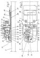
- Figure 1 is a central longitudinal cross-sectional view of the front-piece of a first embodiment of the invention, with the mounting of the spring not being shown as a cross-sectional view ;
- Figure 2 is a partially cut plan view of the front-piece of Figure 1 ;
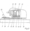
- Figure 3 is a front-piece according to a second embodiment in a partially cut side view;
- Figure 4 is a plan view of a front-piece of another embodiment;
- Figure 5 is a central longitudinal sectional view of the front-piece of Figure 4 ;
- Figure 6 is a sectional view along line VI-VI in Figure 5 ;
- Figure 7 is a plan view seen from
arrow 7 in Figure 5 ; and, - Figures 8 and 9 are representations similar to Figures 6 and 7 in a situation where the contro) means are actuated.
- The front-piece shown in Figures 1 and 2 comprises a housing mounted on a
ski 2 by means ofscrews 1. The housing comprises anupper portion 4, abottom portion 3 and acover cap 5 with all said elements being fixedly mounted together. With regard to Figure 1 the housing has in substance the form of a U. The legs of the U are connected to each other by means of a centrally locatedrivet 6. In the area of this riveting a separatingmember 7 is provided between those legs. The separatingmember 7 serves with its two side-edges as an abutment for a pair of pivot levers 8 and 9, respectively. The pivot levers 8 and 9, respectively, form supporting members for two sole-holders holders screw 12. Each of sole-holders screw 12. It should be noted, however, thatscrew 12 is supported in the supporting member in a rotatable but axially immovable manner. Each of pivot levers 8, 9 is pivotally mounted on anaxis forming bolt 13.Bolts 13 are arranged between the legs of the housing and extend parallel to rivet 6. In Figure 2 onlybolt 13 forpivot lever 8 is shown. The second bolt which is arranged symmetrically with respect to the first-mentioned bolt cannot be seen in Figure 2 because it is covered bycover cap 5. - The pivot levers and sole-
holder support members legs legs guide roller 17 is guided,guide roller 17 being rotatably mounted on thesame axle 18. Between the twoguide rollers 17 of eachpivot lever spring 19 is mounted on each of the axles. Pullingspring 19 will normally maintain thepivot levers member 7. The guide-rollers 17, besides being guided inelongated holes 16, are also guided in a guide or supportingmember 20.Member 20 is also a substantially U-shaped sheet metalmember having legs - The side faces of
legs guide rollers 17 in the normal position of the pivot levers 8, 9. Aweb 23 ofmember 20 is provided with a threaded hole into which the shaft of ascrew 24 is threaded. Screw 24 holdsmember 20 in the housing. The front-piece described so far is known from the prior art so that an even more detailed description is not necessary. Regarding the structure and the function, reference is made for example to DE-A-2 034 355. - The
bottom portion 3 of the housing is extended at its one part which forms one of the U-Iegs. The extension of this one part goes beyond the connectingrivet 6 and forms a steppingplate 25 in which apedal 26 is vertically movable in a limited manner. This pedal forms part of a control means of the preferred forms of the invention. The control means serves to keep the release resistance at least substantially constant, regardless of the variable pressure applied to pedal 26. -
Pedal 26 is provided at its bottom side with apush wedge 27 for the actuation of aslide element 28. Theslide element 28 is movably mounted in longitudinal direction in the leg of the bottom portion of the housing. Theslide element 28 has, as shown in the figure, at its left end a vertically extendingangle portion 29. Theangle portion 29 comprises a recess for fittingly receiving acollar 30 which is provided on thescrew 24. Also acting on theangle portion 29 is areset spring 31 which is supported in the housing. Thereset spring 31 maintains theslide element 28 and consequently also the pedal 26 in their respective normal positions. In the event that a ski boot presses the pedal downwards due to increased load on the ball of the foot, then this has the consequence of moving theslide element 28 and, consequently, thescrew 24. Inasmuch as the guide and supportingmember 20 is screwed to thescrew 24member 20 as well as thespring 19 supported bymember 20 are moved. As a consequence, the length of the force arm by means of which thespring 19 acts upon thesupport members support members bolts 13. As a result, the release resistance of the spring is reduced and therefore the frictional resistance is compensated for the respective large load of the ball of the foot, so that the entire release resistance with respect to the sideward release of the ski boot is at least approximately kept constant. - The front piece of Figure 3 is provided with a centrally located
sole holder 34,sole holder 34 being pivotally mounted on avertical axis 35. Theaxis 35 is, as is customary, riveted to abase plate 36, a base plate which is in turn screwed to theski 2. By means of a detent device the sole holder is locked in its normal position. This detent device comprises adetent groove 37, adetent ball 38 and adetent spring 39 acting uponball 38. The detent groove is located in the sole holder, while thedetent ball 38 is arranged together with thedetent spring 39 in aspring cage 40. Thespring cage 40 is mounted to thebase plate 36 in a manner described below. - As was described in connection with the front piece shown in Figures 1 and 2, the present front piece is also provided with a
pedal 26, a pedal which is movably mounted in thebase plate 36 in a vertically limited manner. Thepush wedge 27 at the bottom side of the pedal acts also in the present case together with aslide element 41, a slide element which is movably mounted in longitudinal direction inbase plate 36. Theslide element 41 is again under the influence of areset spring 42, which is supported ataxis 35. Theslide element 41 carried asupport 43, saidsupport 43 comprises alongitudinal recess 44 adapted to receive thespring cage 40. Ascrew 45 is rotatably but not axially movably supported insupport 43.Spring cage 40 is screwed to the shaft ofscrew 45. By means of actuation ofscrew 45 the position ofspring cage 40 inlongitudinal recess 44 ofsupport 43 may be changed at will, and consequently also the release resistance of thedetent spring 39. - Similarly to the operation of the first-mentioned embodiment, it is also true for this embodiment that an increasing load of the ball of the foot moves the pedal 26 downwardly, a downward movement which causes the movement of
slide element 41 towards the right (see Figure 3). Due to this movement the distance between thedetent ball 38 and thepivot axis 35 is shortened which causes an automatic reduction of the release resistance of thedetent spring 39. Therefore, in accordance with this embodiment of the invention, the frictional resistance occurring during the sideways release is correspondingly compensated for high ball-of-foot loads, and the total release resistance is maintained approximately constant. - A third embodiment of a front piece according to the invention is shown in Figures 4 to 9. A centrally located
sole holder 48 is linked via anaxis pin 49 to a soleholder support member 50. The soleholder support member 50 is, in turn, pivotally mounted on avertical axle 51. Theaxis 51 is, in turn, riveted to abase plate 52, andbase plate 52 is screwed by means ofscrews 1 onto aski 2. Thesole holder 48 may be secured in its normal position with respect to the sole holder sunport member by means of a centering spring not shown. The sole holder support member is under the influence of apressure member 53. Thepressure member 53 is under the load of acoil pressure spring 54 and keeps the soleholder support member 50 in its normal position. -
Spring 54 abuts against avertical cross wall 55, a cross wall which is fixedly connected with the base plate or which is formed as a single piece together with the base plate. Thecross wall 55 is arranged on ashaft 56 of thepressure member 53. Theshaft 56 is rotatably and axially movably mounted in a bore of thecross wall 55. The end of theshaft 56 is provided withteeth 57. Thepressure member 53 is provided at its side opposite to thespring 54 with twoteeth 58 which are arranged diametrically opposed to each other. The tips ofteeth 58 serve as pressure transfer points and normally center the soleholder support member 50 symmetrically with respect to the vertical longitudinal plane of the front piece. - Again, for this embodiment of the invention, as was true for the embodiments described above, a pedal which is not shown is provided. This pedal again is movably mounted on the
base plate 52 in a vertically limited manner and it cooperates by means of a push wedge with aslide element 59. Again slide element. 59 is movably mounted in the base plate in the longitudinal direction of the front piece. Theslide element 59 comprises an elongated hole. Theaxis 51 extends (see Figure 5), through the elongated hole and a reset spring, for instance arubber spring 60, is received in the elongated hole ; resetspring 60 abutsaxle 51. As is shown in Figures 4 and 5 the right-hand end of theslide member 59 cooperates with the verticallymovable stem 61 which is mounted in thecross wall 55.Stem 61 is also under the influence of a reset spring which is not shown in Figure 9 and which is represented by thearrow 62.Stem 61 is provided at its free end with anelongated hole 63 extending transversly with respect to the direction of movement. Acrank pin 64 is in engagement withelongated hole 63. Crankpin 64 is provided at arotary disc 65. Therotary disc 65 is arranged on the toothed end of theshaft 56. Therotary disc 65 is provided for this purpose with a hole having corresponding meshing teeth. Consequently, theshaft 56 is not rotatable with respect to therotary disc 65, but axially movable. Therotary disc 65 is secured against axial movement by means of thestem 61. - As is true for the embodiments described above, for the present embodiment an increase in the ball-of-the-foot load causes, via the pedal, a movement of the
slide element 59 towards the right-hand side looking at Figures 4 and 5. Theslide element 59 moves thestem 61 upwardly during such movement as a consequence of which movement therotary disc 65 is moved from its position shown in Figure 7 to its position shown in Figure 9. Simultaneously, this movement causes a rotary movement of the shaft and, consequently, of thepressure member 53 from the position of Figure 6 to the position of Figure 8. - Therefore, the distance of the pressure transfer points of the
pressure member 53 with respect to the vertical longitudinal plane is reduced by the amount « a ». This distance is now the arm of the moment due to the force of thespring 54. According to this embodiment of the invention the release resistance of the spring is varied depending on the pressure of the ball of the foot such that for the sideways release of the front piece the total release resistance is in each case approximately the same. - In accordance with another feature of the invention, a control means is provided between the sole holder and the spring, a control means which moves the spring in the above-described sense. The control means is provided such that even in the reverse situation with heavy backward load the friction between the ski boot sole and the sole holder is compensated, a friction which will influence the sideways release. This feature is particularly valuable for a so-called single linkage front piece.
Claims (11)
Priority Applications (1)
| Application Number | Priority Date | Filing Date | Title |
|---|---|---|---|
| AT85905789T ATE50402T1 (en) | 1984-10-05 | 1985-10-04 | FRONT PIECE FOR SAFETY SKI BINDING. |
Applications Claiming Priority (2)
| Application Number | Priority Date | Filing Date | Title |
|---|---|---|---|
| DE19843436672 DE3436672A1 (en) | 1984-10-05 | 1984-10-05 | FRONT JAWS FOR SAFETY SKI BINDINGS |
| DE3436672 | 1984-10-05 |
Publications (2)
| Publication Number | Publication Date |
|---|---|
| EP0200774A1 EP0200774A1 (en) | 1986-11-12 |
| EP0200774B1 true EP0200774B1 (en) | 1990-02-14 |
Family
ID=6247243
Family Applications (1)
| Application Number | Title | Priority Date | Filing Date |
|---|---|---|---|
| EP85905789A Expired EP0200774B1 (en) | 1984-10-05 | 1985-10-04 | Frontpiece for safety skibinding |
Country Status (4)
| Country | Link |
|---|---|
| EP (1) | EP0200774B1 (en) |
| JP (1) | JPS62500637A (en) |
| DE (1) | DE3436672A1 (en) |
| WO (1) | WO1986002012A1 (en) |
Families Citing this family (3)
| Publication number | Priority date | Publication date | Assignee | Title |
|---|---|---|---|---|
| DE3616958A1 (en) * | 1986-05-20 | 1987-11-26 | Marker Deutschland Gmbh | FRONT JAWS FOR SAFETY SKI BINDINGS |
| DE3734492A1 (en) * | 1987-10-12 | 1989-04-20 | Geze Sport | BEFORE A FRONT STAND OF A SKIS, FRONT BAKES OF A SAFETY SKI BINDING |
| DE19519826A1 (en) * | 1995-05-31 | 1996-12-05 | Blohm Maschinenbau Gmbh | Trimming tool for grinding wheels with main tool body |
Family Cites Families (4)
| Publication number | Priority date | Publication date | Assignee | Title |
|---|---|---|---|---|
| DE2030749B2 (en) * | 1970-06-23 | 1979-02-08 | Vereinigte Baubeschlagfabriken Gretsch & Co Gmbh, 7250 Leonberg | Safety ski binding with a device to disengage the ski boot from the side |
| US3734521A (en) * | 1970-07-10 | 1973-05-22 | Marker Hannes | Toe iron for safety ski bindings |
| DE2209055C3 (en) * | 1972-02-25 | 1984-04-19 | Marker, Hannes, 8100 Garmisch-Partenkirchen | Toe piece for safety ski bindings |
| FR2523857A1 (en) * | 1982-03-25 | 1983-09-30 | Salomon & Fils F | SECURITY FASTENING FOR SKI |
-
1984
- 1984-10-05 DE DE19843436672 patent/DE3436672A1/en not_active Withdrawn
-
1985
- 1985-10-04 WO PCT/EP1985/000519 patent/WO1986002012A1/en not_active Ceased
- 1985-10-04 JP JP60505085A patent/JPS62500637A/en active Pending
- 1985-10-04 EP EP85905789A patent/EP0200774B1/en not_active Expired
Also Published As
| Publication number | Publication date |
|---|---|
| WO1986002012A1 (en) | 1986-04-10 |
| EP0200774A1 (en) | 1986-11-12 |
| JPS62500637A (en) | 1987-03-19 |
| DE3436672A1 (en) | 1986-04-10 |
Similar Documents
| Publication | Publication Date | Title |
|---|---|---|
| US4735435A (en) | Front-piece for a safety ski-binding | |
| US3610650A (en) | Ski boot holding clamp | |
| US4538828A (en) | Safety ski binding | |
| US4401318A (en) | Toe abutment member for a ski binding | |
| US4889359A (en) | Laterally releasable jaw unit of a safety ski binding | |
| US5722681A (en) | Alpine ski binding apparatus | |
| US5040821A (en) | Safety binding for a ski | |
| US5096218A (en) | Safety ski binding | |
| US4735434A (en) | Toe piece for a safety ski-binding | |
| US4298213A (en) | Ski safety binding of the diagonal release type | |
| US4600213A (en) | Safety ski-binding having a sole plate | |
| US5687982A (en) | Element and assembly for retaining a boot on a gliding board | |
| US4362313A (en) | Toe abutment member for a ski binding | |
| US4913456A (en) | Front-piece for a safety ski-binding | |
| US4984816A (en) | Safety binding | |
| US5639108A (en) | Boot-retention element assembly, particularly for skiing | |
| US5015005A (en) | Front-piece for a safety ski-binding | |
| US4709942A (en) | Safety ski binding including an automatic compensation mechanism | |
| WO1986002012A1 (en) | Frontpiece for safety skibinding | |
| US4997199A (en) | Foot plate for a ski binding | |
| US4682786A (en) | Safety ski binding | |
| US4960289A (en) | Endpiece body for safety ski bindings | |
| EP0016777B1 (en) | Safety ski binding | |
| US4779891A (en) | Safety ski binding | |
| US4684146A (en) | Heel holder |
Legal Events
| Date | Code | Title | Description |
|---|---|---|---|
| PUAI | Public reference made under article 153(3) epc to a published international application that has entered the european phase |
Free format text: ORIGINAL CODE: 0009012 |
|
| 17P | Request for examination filed |
Effective date: 19860616 |
|
| AK | Designated contracting states |
Kind code of ref document: A1 Designated state(s): AT FR |
|
| 17Q | First examination report despatched |
Effective date: 19880211 |
|
| GRAA | (expected) grant |
Free format text: ORIGINAL CODE: 0009210 |
|
| AK | Designated contracting states |
Kind code of ref document: B1 Designated state(s): AT FR |
|
| REF | Corresponds to: |
Ref document number: 50402 Country of ref document: AT Date of ref document: 19900215 Kind code of ref document: T |
|
| ET | Fr: translation filed | ||
| PGFP | Annual fee paid to national office [announced via postgrant information from national office to epo] |
Ref country code: AT Payment date: 19900919 Year of fee payment: 6 |
|
| PLBE | No opposition filed within time limit |
Free format text: ORIGINAL CODE: 0009261 |
|
| STAA | Information on the status of an ep patent application or granted ep patent |
Free format text: STATUS: NO OPPOSITION FILED WITHIN TIME LIMIT |
|
| 26N | No opposition filed | ||
| PG25 | Lapsed in a contracting state [announced via postgrant information from national office to epo] |
Ref country code: AT Effective date: 19911004 |
|
| PGFP | Annual fee paid to national office [announced via postgrant information from national office to epo] |
Ref country code: FR Payment date: 19960913 Year of fee payment: 12 |
|
| PG25 | Lapsed in a contracting state [announced via postgrant information from national office to epo] |
Ref country code: FR Free format text: THE PATENT HAS BEEN ANNULLED BY A DECISION OF A NATIONAL AUTHORITY Effective date: 19971031 |
|
| REG | Reference to a national code |
Ref country code: FR Ref legal event code: ST |