EP0200721B1 - Arrangement for communication between equipment belonging to different network architectures - Google Patents
Arrangement for communication between equipment belonging to different network architectures Download PDFInfo
- Publication number
- EP0200721B1 EP0200721B1 EP84904187A EP84904187A EP0200721B1 EP 0200721 B1 EP0200721 B1 EP 0200721B1 EP 84904187 A EP84904187 A EP 84904187A EP 84904187 A EP84904187 A EP 84904187A EP 0200721 B1 EP0200721 B1 EP 0200721B1
- Authority
- EP
- European Patent Office
- Prior art keywords
- equipment
- network
- pieces
- belonging
- conversion equipment
- Prior art date
- Legal status (The legal status is an assumption and is not a legal conclusion. Google has not performed a legal analysis and makes no representation as to the accuracy of the status listed.)
- Expired
Links
Images
Classifications
-
- G—PHYSICS
- G06—COMPUTING OR CALCULATING; COUNTING
- G06F—ELECTRIC DIGITAL DATA PROCESSING
- G06F13/00—Interconnection of, or transfer of information or other signals between, memories, input/output devices or central processing units
- G06F13/38—Information transfer, e.g. on bus
- G06F13/382—Information transfer, e.g. on bus using universal interface adapter
- G06F13/387—Information transfer, e.g. on bus using universal interface adapter for adaptation of different data processing systems to different peripheral devices, e.g. protocol converters for incompatible systems, open system
-
- G—PHYSICS
- G06—COMPUTING OR CALCULATING; COUNTING
- G06F—ELECTRIC DIGITAL DATA PROCESSING
- G06F15/00—Digital computers in general; Data processing equipment in general
- G06F15/16—Combinations of two or more digital computers each having at least an arithmetic unit, a program unit and a register, e.g. for a simultaneous processing of several programs
- G06F15/163—Interprocessor communication
- G06F15/173—Interprocessor communication using an interconnection network, e.g. matrix, shuffle, pyramid, star, snowflake
- G06F15/17356—Indirect interconnection networks
-
- H—ELECTRICITY
- H04—ELECTRIC COMMUNICATION TECHNIQUE
- H04L—TRANSMISSION OF DIGITAL INFORMATION, e.g. TELEGRAPHIC COMMUNICATION
- H04L12/00—Data switching networks
-
- H—ELECTRICITY
- H04—ELECTRIC COMMUNICATION TECHNIQUE
- H04L—TRANSMISSION OF DIGITAL INFORMATION, e.g. TELEGRAPHIC COMMUNICATION
- H04L69/00—Network arrangements, protocols or services independent of the application payload and not provided for in the other groups of this subclass
-
- H—ELECTRICITY
- H04—ELECTRIC COMMUNICATION TECHNIQUE
- H04Q—SELECTING
- H04Q11/00—Selecting arrangements for multiplex systems
- H04Q11/04—Selecting arrangements for multiplex systems for time-division multiplexing
- H04Q11/0428—Integrated services digital network, i.e. systems for transmission of different types of digitised signals, e.g. speech, data, telecentral, television signals
Definitions
- the present invention relates to an arrangement permitting communication between pieces of equipment in a communications network, for example an integrated network for data, telephony, text and/or images.
- the aforementioned communications network is also of the kind which, in principle, provides the integration of at least two networks with different network architectures.
- the aforementioned communciations network is constructed with its own specific network architecture independent of the architectures of the aforementioned two networks.
- One of the objects of the present invention as claimed in claim 1 is to solve the problem outlined above, and what may be regarded in this respect as being essentially characteristic of the novel arrangement is that connections between pieces of equipment belonging to the specific architecture, that is to say to the architecture of the communications network, and a second network architecture are routed via a first piece of conversion equipment, and that connections between pieces of equipment belonging to two other network architectures are routed via a second piece and said first piece of conversion equipment wired in series.
- the first pieces of conversion equipment should be so arranged as to be utilized for the conversion of link protocols between equipment in the specific network architecture (i.e. that of the communciations network) and equipment in each of the aforementioned other network architectures, and that the second pieces of conversion equipment should be so arranged as to be wired in series with the aforementioned first pieces of conversion equipment for the purpose of the conversion of trace routines between equipment belonging to two of the aforementioned other network architectures.
- a communications network for instance an integrated network for data, telephony, text and/or images, is indicated by K in Figure 1.
- the design of the network may be of a previously disclosed type and will accordingly not be described here in detail, but is shown only in principle by means of a selector symbol V and inputs and outputs in the network.
- a number of terminals T1, T2, T3, T4 are connected to the network via storage devices RT-CI, RT-S, RT-D and RT-E for the purpose of determining the path selection in the network.
- To the network are also connected host computers or processors P1, P2, P3 and P4, these designations being able to represent not only the processors but also mail boxes, text conference equipment, and connection equipment to other networks, etc.
- the aforementioned pieces of equipment can also include multiplexers and concentrators.
- Each of the terminals T1 ⁇ T4 shall be capable of being linked to the aforementioned pieces of equipment P1 ⁇ P4 for the purpose of performing different operating tasks.
- the host computers are able to perform different operating tasks. Two or more computers can, of course, perform the same operating task, should the need for the operating task in question to be performed exist within the network.
- Each of the terminals is thus capable of being connected to one or more computers via the network.
- the design illustrated includes pieces of specific path selection equipment RI, RS, RD and RE, to which the terminals are automatically connected via the network when they are activated.
- the pieces of path selection equipment are connected to outputs of the selection network in accordance with Figure 1, but may, as an alternative or in addition, be arranged inside or adjacent to one or more of the pieces of equipment Pl-P4. The latter case will be of interest, for example, when a terminaJ is used almost exclusively with a single processor, which is provided in this way with a piece of path selection equipment of this kind.
- a network which provides the integration of networks with a number, being in the case illustrated three, of different network architectures. Terminals, processors and path selection equipment are provided in this case for each of the network architectures, and also for the integrated network as such.
- the terminal T1 the storage device RT-CI for path selection information, the path selection equipment RI and the processor P4 are matched to the overall integrated network architecture, referred to here as ICNA, which is the preferred designation for the Integrated Communications Network Architecture used by the Swedish Telecommunications Administration.
- T2, RT-S, RS and P3 are matched to a network architecture in accordance with SNA (System Network Architecture), which constitutes a first network architecture developed for a company.
- T3, RT-D, RD and P1 are contained in the DCNA (Distributed Communication Network Architecture) network architecture, which constitutes a second network architecture developed for a company.
- T4, RT-E, RE and P2 are contained in the DECNET (Digital Equipment Computer Network) network architecture, which constitutes a third network architecture developed for a company.
- DECNET Digital Equipment Computer Network
- the network design includes CIS conversion equipment, which is conversion equipment between ICNA and SNA.
- CIE is conversion equipment between ICNA and DECNET, CID between ICNA and DCNA, CSI between SNA and ICNA (which can be the same as CIS), CEI between DECNET and ICNA (which can be the same as CIE), and CDI between DCNA and ICNA (which can be the same as CID).
- SNA Small Cellular Network
- DCNA Low-power amplifier
- DECNET Low-power amplifier
- ICNA overlaps all three of the aforementioned architectures and presupposes the use of the OSI-mode ⁇ (Open System Interconnection), on condition that OSI has been defined.
- OSI-mode ⁇ Open System Interconnection
- one terminal of the aforementioned terminals T1 ⁇ T4 When one terminal of the aforementioned terminals T1 ⁇ T4 is occupied or is activated, it will be connected automatically to the path selection equipment RI, RS, RD or RE, of the group or architecture to which it belongs.
- the operator initiates his work at the terminal by indicating the designation of the task which he wishes to perform.
- the path selection equipment translates the name of the task into path selection information which is transmitted back to the storage device of the terminal, that is to say to one of the pieces of path selection equipment RT-CI, RT-S, RT-D or RT-E.
- the storage equipment for the terminal concerned controls the establishment of the connection to that processor which is able to perform the task.
- Each piece of path selection equipment may conveniently also be so arranged as to provide automatic switching over from one computer which is already linked to another computer. This may be of interest if the operating task at the terminal changes, and if it is wished to have performed another type of work which the computer concerned is unable to execute. Another reason for the aforementioned switching over is that the computer concerned may be required to perform a task of higher priority than that with which it is involved at the time.
- one or more terminals are designed in such a way that each terminal for each computer and/or each piece of path selection equipment is able to transmit a code which describes the characteristics and design of the terminal for example the key arrangement, graphics, capabilities, colour, and print-out capabilities, etc.
- the path selection equipment is able in a preferred embodiment to take into account the aforementioned terminal characteristics when selecting the computer.
- the path selection equipment notifies the terminal of any restrictions on the use of the terminal for the desired task.
- the path selection equipment can also notify the terminals of the type of terminal which should be used if complete processing of the task is desired.
- the aforementioned information can also be provided by the computer if information relating to the type of terminal is transmitted further to the computer.
- connection between, for example, SNA terminal T2 and the DCNA processor P1 is routed via the selector network V, the conversion equipment CSI, the fixed connection 1, once more through the selector network, and the conversion equipment CID.
- T2 communicates with P2 via V, CDI, the connection 2, V and CIE, and so on.
- the concept for the equipment illustrated contains functions for the control, monitoring and administration of the network, which is shown clearly in Figure 2.
- the pieces of path selection equipment connected to the network K in Figure 1 are indicated in Figure 2 by the designation R.
- the pieces of conversion equipment and the processors in accordance with Figure 1 are included in a similar fashion in Figure 2 and are indicated respectively by the designations C and P.
- the central monitoring organs in the network are symbolized by CDP (Central Monitoring Processors).
- Control paths 1-6 are indicated by arrows.
- the arrow 1 indicates the possibility for changing the path selection information, the blocking of certain traffic and/or the allocation of priority to certain traffic via the pieces of equipment R.
- the arrow 2 indicates availability information and/or traffic statistics from the path selection equipment.
- the arrow 3 indicates availability information and/or traffic statistics from the conversion equipment, whereas the arrow 4 indicates corresponding information or statistics from the processors P.
- the processors can also be controlled so as to allocate priority to certain traffic, as indicated by the arrow 5.
- the interruption of certain connections, for example those with low priority, can also be controlled; see the arrow 6.
- the central monitoring processors may be of a previously disclosed type and may include connections for a printer S, a screen B and a keyboard TA, etc.
- Changes to traffic path information shall be capable of being made from appropriate central points in the network, cf. CDP, which will reach the pieces of path selection equipment R via separate selectors.
- the terminals and the operators must identify themselves to the path selection equipment R so that the latter can select path or, if necessary, block traffic on the basis of its origin.
- Processors and pieces of conversion equipment shall meter their traffic continuously and shall notify blocking situations to the central monitoring points of the network, which in turn control the operation of the path selection equipment.
- the path selection equipment shall be able to communicate with the central monitoring points of the network and shall notify any communication requirements which cannot be executed. The possibility shall be afforded to interrupting connections of low priority via the processors from a central point in the network, should the information from the path selection equipment so require.
Landscapes
- Engineering & Computer Science (AREA)
- Theoretical Computer Science (AREA)
- Physics & Mathematics (AREA)
- Computer Networks & Wireless Communication (AREA)
- General Physics & Mathematics (AREA)
- General Engineering & Computer Science (AREA)
- Signal Processing (AREA)
- Computer Hardware Design (AREA)
- Computer Security & Cryptography (AREA)
- Mathematical Physics (AREA)
- Software Systems (AREA)
- Computer And Data Communications (AREA)
- Data Exchanges In Wide-Area Networks (AREA)
- Communication Control (AREA)
- Multi Processors (AREA)
Abstract
Description
- The present invention relates to an arrangement permitting communication between pieces of equipment in a communications network, for example an integrated network for data, telephony, text and/or images. The aforementioned communications network is also of the kind which, in principle, provides the integration of at least two networks with different network architectures. The aforementioned communciations network is constructed with its own specific network architecture independent of the architectures of the aforementioned two networks. There are connected to the selector system of the communications network pieces of conversion equipment via which connections between pieces of equipment for different network architectures are capable of being linked.
- The different companies which market different pieces of equipment on the open market, for example computers and terminals, etc., and their associated communications systems, stipulate the use of designs specific to that particular company, which means that the system of one company will not, as a general rule, be compatible with the system of another company. The following may be mentioned as examples of previously disclosed systems: SNA (System Network Architecture), DCNA (Distributed Communication Network Architecture), and DECNET (Digital Equipment Computer Network).
- There is a general wish for the expansion of data communications networks of the type in question, to which connection is possible and in which communication can be provided between the pieces of equipment which are specific to the different companies. This presupposes, amongst other things, the use of conversion equipment, and it is desirable in this respect that the designs of the components concerned should be simple, and that the range of components should be kept to a minimum.
- One of the objects of the present invention as claimed in
claim 1 is to solve the problem outlined above, and what may be regarded in this respect as being essentially characteristic of the novel arrangement is that connections between pieces of equipment belonging to the specific architecture, that is to say to the architecture of the communications network, and a second network architecture are routed via a first piece of conversion equipment, and that connections between pieces of equipment belonging to two other network architectures are routed via a second piece and said first piece of conversion equipment wired in series. - In further developments of the idea of invention it is proposed that the first pieces of conversion equipment should be so arranged as to be utilized for the conversion of link protocols between equipment in the specific network architecture (i.e. that of the communciations network) and equipment in each of the aforementioned other network architectures, and that the second pieces of conversion equipment should be so arranged as to be wired in series with the aforementioned first pieces of conversion equipment for the purpose of the conversion of trace routines between equipment belonging to two of the aforementioned other network architectures.
- The solution proposed above will permit the number of pieces of conversion equipment to be kept to a minimum, at the same time as a comparatively simple design can be retained for each of the pieces of conversion equipment.
- A preferred embodiment of the arrangement which exhibits the significant characteristic features of the invention is described below with reference to the accompanying drawing.
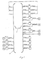
- Figure 1 shows in the form of a block diagram the basic design of a communications network having, amongst other things, terminals, processors and path selection equipment; and
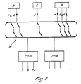
- Figure 2 shows in the form of a block diagram the basic design of the central monitoring organs in the network in accordance with Figure 1.
- A communications network, for instance an integrated network for data, telephony, text and/or images, is indicated by K in Figure 1. The design of the network may be of a previously disclosed type and will accordingly not be described here in detail, but is shown only in principle by means of a selector symbol V and inputs and outputs in the network.
- A number of terminals T1, T2, T3, T4 are connected to the network via storage devices RT-CI, RT-S, RT-D and RT-E for the purpose of determining the path selection in the network. To the network are also connected host computers or processors P1, P2, P3 and P4, these designations being able to represent not only the processors but also mail boxes, text conference equipment, and connection equipment to other networks, etc. The aforementioned pieces of equipment can also include multiplexers and concentrators. Each of the terminals T1―T4 shall be capable of being linked to the aforementioned pieces of equipment P1―P4 for the purpose of performing different operating tasks. In this respect the host computers are able to perform different operating tasks. Two or more computers can, of course, perform the same operating task, should the need for the operating task in question to be performed exist within the network. Each of the terminals is thus capable of being connected to one or more computers via the network.
- In accordance with the invention, the design illustrated includes pieces of specific path selection equipment RI, RS, RD and RE, to which the terminals are automatically connected via the network when they are activated. The pieces of path selection equipment are connected to outputs of the selection network in accordance with Figure 1, but may, as an alternative or in addition, be arranged inside or adjacent to one or more of the pieces of equipment Pl-P4. The latter case will be of interest, for example, when a terminaJ is used almost exclusively with a single processor, which is provided in this way with a piece of path selection equipment of this kind.
- In the embodiment shown, use is made of a network which provides the integration of networks with a number, being in the case illustrated three, of different network architectures. Terminals, processors and path selection equipment are provided in this case for each of the network architectures, and also for the integrated network as such.
- The terminal T1, the storage device RT-CI for path selection information, the path selection equipment RI and the processor P4 are matched to the overall integrated network architecture, referred to here as ICNA, which is the preferred designation for the Integrated Communications Network Architecture used by the Swedish Telecommunications Administration. T2, RT-S, RS and P3 are matched to a network architecture in accordance with SNA (System Network Architecture), which constitutes a first network architecture developed for a company. T3, RT-D, RD and P1 are contained in the DCNA (Distributed Communication Network Architecture) network architecture, which constitutes a second network architecture developed for a company. T4, RT-E, RE and P2 are contained in the DECNET (Digital Equipment Computer Network) network architecture, which constitutes a third network architecture developed for a company.
- In order to permit communication between terminals and processors of different architectures, the network design includes CIS conversion equipment, which is conversion equipment between ICNA and SNA. Similarly, CIE is conversion equipment between ICNA and DECNET, CID between ICNA and DCNA, CSI between SNA and ICNA (which can be the same as CIS), CEI between DECNET and ICNA (which can be the same as CIE), and CDI between DCNA and ICNA (which can be the same as CID).
- The aforementioned architectures SNA, DCNA and DECNET represent at the present time the most common network architectures and link protocols. ICNA overlaps all three of the aforementioned architectures and presupposes the use of the OSI-modeí (Open System Interconnection), on condition that OSI has been defined.
- When one terminal of the aforementioned terminals T1―T4 is occupied or is activated, it will be connected automatically to the path selection equipment RI, RS, RD or RE, of the group or architecture to which it belongs. The operator initiates his work at the terminal by indicating the designation of the task which he wishes to perform. The path selection equipment translates the name of the task into path selection information which is transmitted back to the storage device of the terminal, that is to say to one of the pieces of path selection equipment RT-CI, RT-S, RT-D or RT-E. The storage equipment for the terminal concerned controls the establishment of the connection to that processor which is able to perform the task.
- Each piece of path selection equipment may conveniently also be so arranged as to provide automatic switching over from one computer which is already linked to another computer. This may be of interest if the operating task at the terminal changes, and if it is wished to have performed another type of work which the computer concerned is unable to execute. Another reason for the aforementioned switching over is that the computer concerned may be required to perform a task of higher priority than that with which it is involved at the time.
- In a preferred embodiment one or more terminals are designed in such a way that each terminal for each computer and/or each piece of path selection equipment is able to transmit a code which describes the characteristics and design of the terminal for example the key arrangement, graphics, capabilities, colour, and print-out capabilities, etc. The path selection equipment is able in a preferred embodiment to take into account the aforementioned terminal characteristics when selecting the computer. The path selection equipment notifies the terminal of any restrictions on the use of the terminal for the desired task. The path selection equipment can also notify the terminals of the type of terminal which should be used if complete processing of the task is desired. The aforementioned information can also be provided by the computer if information relating to the type of terminal is transmitted further to the computer.
- Different instances of link protocol conversion may occur in accordance with the above. If the terminal and the processor are matched to the same architecture and link protocol, no conversion equipment will be linked in. Conversion equipment will be required if either the processor or the terminal is matched to ICNA. If neither the terminal nor the processor is matched to ICNA, then two pieces of conversion equipment will require to be linked together via ICNA. The connection between the ICNA terminal T1 and the SNA processor P3 is routed via the selector network V and the conversion equipment CIS. Similarly, T1 is connected to P1 and P2 via CID and CIE respectively. The connection between, for example, SNA terminal T2 and the DCNA processor P1 is routed via the selector network V, the conversion equipment CSI, the
fixed connection 1, once more through the selector network, and the conversion equipment CID. T2 communicates with P2 via V, CDI, theconnection 2, V and CIE, and so on. - The Table below shows the occasions when the different pieces of conversion equipment are required.

- The concept for the equipment illustrated contains functions for the control, monitoring and administration of the network, which is shown clearly in Figure 2. The pieces of path selection equipment connected to the network K in Figure 1 are indicated in Figure 2 by the designation R. The pieces of conversion equipment and the processors in accordance with Figure 1 are included in a similar fashion in Figure 2 and are indicated respectively by the designations C and P. The central monitoring organs in the network are symbolized by CDP (Central Monitoring Processors). Control paths 1-6 are indicated by arrows. The
arrow 1 indicates the possibility for changing the path selection information, the blocking of certain traffic and/or the allocation of priority to certain traffic via the pieces of equipment R. Thearrow 2 indicates availability information and/or traffic statistics from the path selection equipment. Thearrow 3 indicates availability information and/or traffic statistics from the conversion equipment, whereas the arrow 4 indicates corresponding information or statistics from the processors P. The processors can also be controlled so as to allocate priority to certain traffic, as indicated by the arrow 5. The interruption of certain connections, for example those with low priority, can also be controlled; see the arrow 6. - The central monitoring processors may be of a previously disclosed type and may include connections for a printer S, a screen B and a keyboard TA, etc.
- Changes to traffic path information shall be capable of being made from appropriate central points in the network, cf. CDP, which will reach the pieces of path selection equipment R via separate selectors. The terminals and the operators must identify themselves to the path selection equipment R so that the latter can select path or, if necessary, block traffic on the basis of its origin. Processors and pieces of conversion equipment shall meter their traffic continuously and shall notify blocking situations to the central monitoring points of the network, which in turn control the operation of the path selection equipment. The path selection equipment shall be able to communicate with the central monitoring points of the network and shall notify any communication requirements which cannot be executed. The possibility shall be afforded to interrupting connections of low priority via the processors from a central point in the network, should the information from the path selection equipment so require.
Claims (3)
Applications Claiming Priority (1)
| Application Number | Priority Date | Filing Date | Title |
|---|---|---|---|
| PCT/SE1984/000351 WO1986002749A1 (en) | 1984-10-23 | 1984-10-23 | Arrangement for communication between equipment belonging to different network architectures |
Publications (2)
| Publication Number | Publication Date |
|---|---|
| EP0200721A1 EP0200721A1 (en) | 1986-11-12 |
| EP0200721B1 true EP0200721B1 (en) | 1988-08-24 |
Family
ID=20354435
Family Applications (1)
| Application Number | Title | Priority Date | Filing Date |
|---|---|---|---|
| EP84904187A Expired EP0200721B1 (en) | 1984-10-23 | 1984-10-23 | Arrangement for communication between equipment belonging to different network architectures |
Country Status (5)
| Country | Link |
|---|---|
| US (1) | US4760395A (en) |
| EP (1) | EP0200721B1 (en) |
| JP (1) | JPS62500887A (en) |
| DE (1) | DE3473717D1 (en) |
| WO (1) | WO1986002749A1 (en) |
Families Citing this family (10)
| Publication number | Priority date | Publication date | Assignee | Title |
|---|---|---|---|---|
| JPS63163944A (en) * | 1986-09-17 | 1988-07-07 | インタ−ナショナル・ビジネス・マシ−ンズ・コ−ポレ−ション | Application communication system |
| JPS6388662A (en) * | 1986-10-01 | 1988-04-19 | Hitachi Ltd | Data communication system |
| JP2550642B2 (en) * | 1988-03-04 | 1996-11-06 | 日本電気株式会社 | Packet frame transmission method |
| US5142622A (en) * | 1989-01-31 | 1992-08-25 | International Business Machines Corporation | System for interconnecting applications across different networks of data processing systems by mapping protocols across different network domains |
| US5363121A (en) * | 1990-06-29 | 1994-11-08 | International Business Machines Corporation | Multiple protocol communication interface for distributed transaction processing |
| US5072441A (en) * | 1990-08-07 | 1991-12-10 | Nynex Corporation | Packet switched information network with universal access to enhanced network services |
| US5251205A (en) * | 1990-09-04 | 1993-10-05 | Digital Equipment Corporation | Multiple protocol routing |
| JPH0797782B2 (en) * | 1991-09-18 | 1995-10-18 | インターナショナル・ビジネス・マシーンズ・コーポレイション | How to coordinate heterogeneous transactions |
| GB2313456A (en) * | 1996-05-24 | 1997-11-26 | Ibm | Heterogeneous operations with differing transaction protocols |
| JP4704073B2 (en) * | 2005-03-02 | 2011-06-15 | サンデン株式会社 | Connection device for communication equipment |
Family Cites Families (7)
| Publication number | Priority date | Publication date | Assignee | Title |
|---|---|---|---|---|
| DE2912649C2 (en) * | 1979-03-30 | 1981-10-01 | Siemens AG, 1000 Berlin und 8000 München | Circuit arrangement for the transmission of digital signals between transmitting and / or receiving devices operating with different data transmission procedures and with different data formats via a switching system |
| FR2469751A1 (en) * | 1979-11-07 | 1981-05-22 | Philips Data Syst | SYSTEM INTERCOMMUNICATION PROCESSOR FOR USE IN A DISTRIBUTED DATA PROCESSING SYSTEM |
| JPS57150030A (en) * | 1981-03-13 | 1982-09-16 | Hitachi Ltd | Protocol converter |
| IT1155575B (en) * | 1982-07-27 | 1987-01-28 | Cselt Centro Studi Lab Telecom | MULTIPLE INTERFACE OF COMMUNICATION BETWEEN PROCESS PROCESSOR AND NUMERIC TRANSMISSION VEHICLE |
| JPS5974749A (en) * | 1982-10-22 | 1984-04-27 | Nec Corp | Protocol converting system of ring bus |
| US4547880A (en) * | 1983-05-13 | 1985-10-15 | Able Computer | Communication control apparatus for digital devices |
| US4525830A (en) * | 1983-10-25 | 1985-06-25 | Databit, Inc. | Advanced network processor |
-
1984
- 1984-10-23 WO PCT/SE1984/000351 patent/WO1986002749A1/en not_active Ceased
- 1984-10-23 JP JP59504086A patent/JPS62500887A/en active Pending
- 1984-10-23 EP EP84904187A patent/EP0200721B1/en not_active Expired
- 1984-10-23 US US06/881,359 patent/US4760395A/en not_active Expired - Fee Related
- 1984-10-23 DE DE8484904187T patent/DE3473717D1/en not_active Expired
Also Published As
| Publication number | Publication date |
|---|---|
| EP0200721A1 (en) | 1986-11-12 |
| DE3473717D1 (en) | 1988-09-29 |
| JPS62500887A (en) | 1987-04-09 |
| US4760395A (en) | 1988-07-26 |
| WO1986002749A1 (en) | 1986-05-09 |
Similar Documents
| Publication | Publication Date | Title |
|---|---|---|
| US4513373A (en) | Local area network | |
| US6154449A (en) | Switchless network | |
| US4760395A (en) | Arrangement for communications between equipment belonging to different network architectures | |
| HU192504B (en) | Stored program contolled telecommunication equipment | |
| EP0197930B1 (en) | Arrangement for path selection in a communications network | |
| US4511759A (en) | Apparatus for controlling transfers of files between computers | |
| CN115378454B (en) | Multichannel data link communication system | |
| CN110493040A (en) | The design method and device of airborne network | |
| CA1246726A (en) | Arrangement for communication between equipment belonging to different network architectures | |
| Lissack et al. | Digital switching in local area networks | |
| AU752290B2 (en) | A digital switching equipment | |
| JPH0634351U (en) | Communication structure between facilities belonging to different network architectures | |
| DE69933377D1 (en) | RESOURCE INTERFACE UNIT FOR A REMOTE TERMINATION NODE | |
| JPH1169394A (en) | Sharing method for protocol control memory | |
| US5740162A (en) | ISDN terminal adapter | |
| Matteson | Computer Processing for Data Communications | |
| WO2000013086A1 (en) | Diagnostic system and method for monitoring plural software applications using plural diagnostic tools | |
| US6873699B2 (en) | Network linkage type private branch exchange system and control method thereof | |
| JPH0338197A (en) | Multi-media exchange system | |
| RU29165U1 (en) | TELEGRAPHIC COMMUNICATION CENTER | |
| JPH02260737A (en) | Line switching and packet switching unified switching system | |
| JPH02170742A (en) | System for forming multidrop lan | |
| Leshick et al. | Real Time Data Communications Between Automated Command Centers | |
| JPS62299140A (en) | Data communication system | |
| JPH0537658A (en) | State report system to mtp higher rank user processor at the time of increasing/decreasing mtp level 3 processor in no.7 signal system |
Legal Events
| Date | Code | Title | Description |
|---|---|---|---|
| PUAI | Public reference made under article 153(3) epc to a published international application that has entered the european phase |
Free format text: ORIGINAL CODE: 0009012 |
|
| 17P | Request for examination filed |
Effective date: 19860610 |
|
| AK | Designated contracting states |
Kind code of ref document: A1 Designated state(s): DE FR GB |
|
| 17Q | First examination report despatched |
Effective date: 19871130 |
|
| GRAA | (expected) grant |
Free format text: ORIGINAL CODE: 0009210 |
|
| AK | Designated contracting states |
Kind code of ref document: B1 Designated state(s): DE FR GB |
|
| REF | Corresponds to: |
Ref document number: 3473717 Country of ref document: DE Date of ref document: 19880929 |
|
| ET | Fr: translation filed | ||
| PLBE | No opposition filed within time limit |
Free format text: ORIGINAL CODE: 0009261 |
|
| STAA | Information on the status of an ep patent application or granted ep patent |
Free format text: STATUS: NO OPPOSITION FILED WITHIN TIME LIMIT |
|
| 26N | No opposition filed | ||
| PGFP | Annual fee paid to national office [announced via postgrant information from national office to epo] |
Ref country code: FR Payment date: 19970912 Year of fee payment: 14 |
|
| PGFP | Annual fee paid to national office [announced via postgrant information from national office to epo] |
Ref country code: GB Payment date: 19971009 Year of fee payment: 14 |
|
| PG25 | Lapsed in a contracting state [announced via postgrant information from national office to epo] |
Ref country code: GB Free format text: LAPSE BECAUSE OF NON-PAYMENT OF DUE FEES Effective date: 19981023 |
|
| PGFP | Annual fee paid to national office [announced via postgrant information from national office to epo] |
Ref country code: DE Payment date: 19981231 Year of fee payment: 15 |
|
| GBPC | Gb: european patent ceased through non-payment of renewal fee |
Effective date: 19981023 |
|
| PG25 | Lapsed in a contracting state [announced via postgrant information from national office to epo] |
Ref country code: FR Free format text: LAPSE BECAUSE OF NON-PAYMENT OF DUE FEES Effective date: 19990630 |
|
| REG | Reference to a national code |
Ref country code: FR Ref legal event code: ST |
|
| PG25 | Lapsed in a contracting state [announced via postgrant information from national office to epo] |
Ref country code: DE Free format text: LAPSE BECAUSE OF NON-PAYMENT OF DUE FEES Effective date: 20000801 |