EP0200081B1 - Pumping-up generator/motor system and method of operation of the same - Google Patents
Pumping-up generator/motor system and method of operation of the same Download PDFInfo
- Publication number
- EP0200081B1 EP0200081B1 EP19860105140 EP86105140A EP0200081B1 EP 0200081 B1 EP0200081 B1 EP 0200081B1 EP 19860105140 EP19860105140 EP 19860105140 EP 86105140 A EP86105140 A EP 86105140A EP 0200081 B1 EP0200081 B1 EP 0200081B1
- Authority
- EP
- European Patent Office
- Prior art keywords
- generator
- motor
- mode
- converter
- cyclo
- Prior art date
- Legal status (The legal status is an assumption and is not a legal conclusion. Google has not performed a legal analysis and makes no representation as to the accuracy of the status listed.)
- Expired - Lifetime
Links
- 238000000034 method Methods 0.000 title claims description 10
- 230000001360 synchronised effect Effects 0.000 claims description 18
- XLYOFNOQVPJJNP-UHFFFAOYSA-N water Substances O XLYOFNOQVPJJNP-UHFFFAOYSA-N 0.000 claims description 13
- 230000006698 induction Effects 0.000 claims description 6
- 238000004804 winding Methods 0.000 claims description 4
- 238000010586 diagram Methods 0.000 description 6
- 238000007796 conventional method Methods 0.000 description 2
- 230000000694 effects Effects 0.000 description 2
- 230000033228 biological regulation Effects 0.000 description 1
- 238000010248 power generation Methods 0.000 description 1
- 238000005086 pumping Methods 0.000 description 1
Images

Classifications
-
- H—ELECTRICITY
- H02—GENERATION; CONVERSION OR DISTRIBUTION OF ELECTRIC POWER
- H02P—CONTROL OR REGULATION OF ELECTRIC MOTORS, ELECTRIC GENERATORS OR DYNAMO-ELECTRIC CONVERTERS; CONTROLLING TRANSFORMERS, REACTORS OR CHOKE COILS
- H02P9/00—Arrangements for controlling electric generators for the purpose of obtaining a desired output
- H02P9/42—Arrangements for controlling electric generators for the purpose of obtaining a desired output to obtain desired frequency without varying speed of the generator
-
- H—ELECTRICITY
- H02—GENERATION; CONVERSION OR DISTRIBUTION OF ELECTRIC POWER
- H02P—CONTROL OR REGULATION OF ELECTRIC MOTORS, ELECTRIC GENERATORS OR DYNAMO-ELECTRIC CONVERTERS; CONTROLLING TRANSFORMERS, REACTORS OR CHOKE COILS
- H02P9/00—Arrangements for controlling electric generators for the purpose of obtaining a desired output
- H02P9/007—Control circuits for doubly fed generators
-
- H—ELECTRICITY
- H02—GENERATION; CONVERSION OR DISTRIBUTION OF ELECTRIC POWER
- H02P—CONTROL OR REGULATION OF ELECTRIC MOTORS, ELECTRIC GENERATORS OR DYNAMO-ELECTRIC CONVERTERS; CONTROLLING TRANSFORMERS, REACTORS OR CHOKE COILS
- H02P2101/00—Special adaptation of control arrangements for generators
- H02P2101/10—Special adaptation of control arrangements for generators for water-driven turbines
-
- Y—GENERAL TAGGING OF NEW TECHNOLOGICAL DEVELOPMENTS; GENERAL TAGGING OF CROSS-SECTIONAL TECHNOLOGIES SPANNING OVER SEVERAL SECTIONS OF THE IPC; TECHNICAL SUBJECTS COVERED BY FORMER USPC CROSS-REFERENCE ART COLLECTIONS [XRACs] AND DIGESTS
- Y02—TECHNOLOGIES OR APPLICATIONS FOR MITIGATION OR ADAPTATION AGAINST CLIMATE CHANGE
- Y02E—REDUCTION OF GREENHOUSE GAS [GHG] EMISSIONS, RELATED TO ENERGY GENERATION, TRANSMISSION OR DISTRIBUTION
- Y02E10/00—Energy generation through renewable energy sources
- Y02E10/20—Hydro energy
Definitions
- the present invention relates to a pumping-up generator/motor system for use with a pumping-up power plant, or more in particular to a pumping-up generator/motor system using a wound-rotor type induction machine.
- each cyclo-converter is controlled, when the generator/motor is driven in a motor mode, so as to control the rotational speed of the motor and, when driven in generator mode, so as to regulate the frequency of the generator output at a constant level regardless of the rotational speed of the generator.
- the maximum efficiency of the water turbine is to be maintained in variation of its water head or output in the generator mode, it is necessary to maintain the speed variation in a vicinity of the rotational speed N G .
- the pumping-up output is controlled in the pumping-up mode for improving the stability of the power system, on the other hand, it is necessary to maintain the speed variation in a vicinity of the rotational speed N p .
- the value N G or N p is set to a level approximate to the maximum speed in the control range of the water turbine in the generator mode, pumping-up mode, respectively.
- the speed range is set below the synchronous speed in the generator mode as shown in Fig. 4.
- the speed control range in the generator mode is narrowed thereby to reduce the average efficiency.
- a generator/motor of this type using a cyclo-converter is disclosed in "IEEE Transactions on Power Apparatus and Systems", Vol. PAS-100, No. 5, May 1981 (Pages 2171 to 2176) and Vol. PAS-99 No. 5, Sept/Oct 1980 (Pages 1828 to 1837).
- the present invention has been developed in view of the above-mentioned facts, and it is an object thereof to provide a method of operation of a generator/motor of this type which is effective to improve the efficiency in the generator mode and to provide a wide speed control range in the motor operation mode, without increasing the capacity of the cyclo-converter.
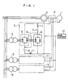
- Fig. 1 is a system diagram showing a method of operation according to the present invention.
- Fig. 2 is a diagram showing speed ranges in the generator mode and motor mode, respectively.
- Fig. 3 is a diagram showing the relationship between the speed ranges and the synchronous speed.
- Fig. 4 is a diagram showing an operation range for a conventional system.
- Fig. 5 is a diagram showing an operation range according to the present invention.
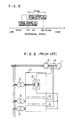
- Fig. 6 is a system diagram for explaining a method of operation according to the prior art.
- a generator/motor 2 of a wound-rotor induction motor structure is connected to a water turbine 1 which acts as a prime mover in the generator mode and a load in the motor mode.
- Each cycle-converter 3 is supplied with a commercial frequency reduced or boosted through a transformer 5 from the power system, converts it into a slip frequency, and supplies the converted frequency to the rotor winding of the generator/motor 2 through a slip ring 4.
- the cyclo-converter 3 includes a plurality of bridge-connection converter units 6 of the same specification.
- the cyclo-converter 3 includes switches 7, 8 and 9 which are closed or opened by control of a switch changer 10 depending on the operation mode of the converter 3. .
- the switches 7 and 9 are opened and the switch 8 is closed.
- the voltage capacity of the converter is a multiple of the number of the converter units 6 connected in series. It is therefore possible to drive the motor with a slip larger than with a single bridge.
- the switches 7 and 9 are closed, while the switch 8 is opened.
- reactors 11 are provided to reduce a circulating current through the parallel-connected converter units 6.
- connection to the transformer 5 may be switched to a lower voltage tap provided in the low-voltage winding (not shown) of the transformer 5.
- the value of the output voltage is set to about the rated voltage for motor operation divided by the number of the parallel-connected converter units. In this way, the current capacity of the frequency converter 3 is multiplied by the number of parallel-connected units, thereby enabling the generator to be driven at about the synchronous speed.
- the center of the speed range of the water turbine in the generator mode is set to about the synchronous speed.
- the maximum slip Smax (G) in the generator mode is set to be almost the same as the maximum slip Smax (D) in the motor or pumping-up mode divided by the number Np of parallel-connected converter units, i.e.
Landscapes
- Engineering & Computer Science (AREA)
- Power Engineering (AREA)
- Control Of Eletrric Generators (AREA)
- Control Of Water Turbines (AREA)
Description
- The present invention relates to a pumping-up generator/motor system for use with a pumping-up power plant, or more in particular to a pumping-up generator/motor system using a wound-rotor type induction machine.
- Prior to explanation of a conventional method of operating a generator/motor system of this type such as a supersynchronous Scherbius system, explanation will be made about a system therefor. Such a system as disclosed in U. S. Patent 4,481,455 issued to Sugimoto et. al. on November 6, 1984 includes a generator/motor 2 selectively driving a water turbine 1 as a load machine in a motor mode or driven by a prime mover in a generator mode as shown in Fig. 6. This generator/motor has a structure of a wound-rotor type induction machine with and its rotor is connected to cyclo-
converters 3 through slip rings 4. Each cyclo-converter 3 is connected to a power line system through atransformer 5. - In operation thereof, each cyclo-converter is controlled, when the generator/motor is driven in a motor mode, so as to control the rotational speed of the motor and, when driven in generator mode, so as to regulate the frequency of the generator output at a constant level regardless of the rotational speed of the generator.
- In this configuration and operation, however, when the cyclo-converter is driven at a vicinity of its synchronous speed (where the slip is small), the polarity of direction of the current flowing in the cyclo-converter is changed at a relatively long time interval and hence the current of the cyclo-converter flows mainly through one side of the inverse-parallel connected rectifiers of the cyclo-converter. In order to prevent the cyclo-converter from being overheated, therefore, it is required to reduce the output of the generator/motor when it is driven at a vicinity of the synchronous speed where slip is small, or if it is desired not to reduce the output of the generator/motor, it is necessary to use a cyclo-converter of a large capacity.
- In the pumping-up power plant, on the other hand, it is common practice to set the rated water flow rate in operation of the generator mode almost to the same value as that in operation of the motor mode, that is, pumping-up mode. In the case of a turbo machine typically such as a pump-turbine, the rotational speed N G, at which the rated output in the power generation mode is produced at the maximum efficiency, is generally lower than the rotational speed N p at which the rated output in the pumping-up mode is produced. As a result, it is necessary that the speed range of the variable-speed type pumping-up generation system covers the rotational speeds N G and N p.
- Specifically, if the maximum efficiency of the water turbine is to be maintained in variation of its water head or output in the generator mode, it is necessary to maintain the speed variation in a vicinity of the rotational speed N G. When the pumping-up output is controlled in the pumping-up mode for improving the stability of the power system, on the other hand, it is necessary to maintain the speed variation in a vicinity of the rotational speed N p. Generally, the value N G or N p is set to a level approximate to the maximum speed in the control range of the water turbine in the generator mode, pumping-up mode, respectively.
- Now, the relationship between the speed control range and the rotational speed N G or N p will be explained more in detail with reference to Figs. 2 and 3. In the case of a supersynchronous Scherbius system of variable-speed generator/motor, the required capacity of the converter units, such as thyristors, in inverse-parallel conn ection of a cyclo-converter is proportional to the maximum value Smax of the slip S =

where N is the rotating speed and N o is the synchronous speed. If the required capacity of the thyristor elements is to be minimized, therefore, it is necessary to set the synchronous speed N o at a value between the maximum speed Nmax and the minimum speed Nmin in the desired speed range of the generator/motor as shown in Fig. 3 so that the maximum slip Smax becomes smallest with a speed range covering the maximum and minimum speeds Nmax and Nmin. - When a cyclo-converter is used and the generator/motor is driven in a vicinity of the synchronous speed, however, the output frequency of the cyclo-converter is very small near to a direct current, resulting in the necessity of either reducing the output of the generator/motor or increasing the capacity of the cyclo-converter as mentioned above.
- For this reason, in another conventional method, the speed range is set below the synchronous speed in the generator mode as shown in Fig. 4. In this method, however, as compared with the arrangement of Fig. 2 assuming that the maximum slip set value Smax and the capacity of the converter elements are made the same, the speed control range in the generator mode is narrowed thereby to reduce the average efficiency.
- A generator/motor of this type using a cyclo-converter is disclosed in "IEEE Transactions on Power Apparatus and Systems", Vol. PAS-100, No. 5, May 1981 (Pages 2171 to 2176) and Vol. PAS-99 No. 5, Sept/Oct 1980 (Pages 1828 to 1837).
- The present invention has been developed in view of the above-mentioned facts, and it is an object thereof to provide a method of operation of a generator/motor of this type which is effective to improve the efficiency in the generator mode and to provide a wide speed control range in the motor operation mode, without increasing the capacity of the cyclo-converter.
- This problem is solved by the feature of the apparatus Claim 1 and the method Claim 2.
- Fig. 1 is a system diagram showing a method of operation according to the present invention.
- Fig. 2 is a diagram showing speed ranges in the generator mode and motor mode, respectively.
- Fig. 3 is a diagram showing the relationship between the speed ranges and the synchronous speed.
- Fig. 4 is a diagram showing an operation range for a conventional system.
- Fig. 5 is a diagram showing an operation range according to the present invention.
- Fig. 6 is a system diagram for explaining a method of operation according to the prior art.
- The present invention will be explained in detail with reference to an embodiment shown in the accompanying drawings.
- In Fig. 1, a generator/motor 2 of a wound-rotor induction motor structure is connected to a water turbine 1 which acts as a prime mover in the generator mode and a load in the motor mode. Each cycle-
converter 3 is supplied with a commercial frequency reduced or boosted through atransformer 5 from the power system, converts it into a slip frequency, and supplies the converted frequency to the rotor winding of the generator/motor 2 through a slip ring 4. The cyclo-converter 3 includes a plurality of bridge-connection converter units 6 of the same specification. - Further, the cyclo-
converter 3 includes switches 7, 8 and 9 which are closed or opened by control of a switch changer 10 depending on the operation mode of theconverter 3. .In the motor operation mode, the switches 7 and 9 are opened and the switch 8 is closed. As a result, the voltage capacity of the converter is a multiple of the number of theconverter units 6 connected in series. It is therefore possible to drive the motor with a slip larger than with a single bridge. In the generator mode, on the other hand, the switches 7 and 9 are closed, while the switch 8 is opened. In this case, reactors 11 are provided to reduce a circulating current through the parallel-connectedconverter units 6. Further, however, the connection to thetransformer 5 may be switched to a lower voltage tap provided in the low-voltage winding (not shown) of thetransformer 5. The value of the output voltage is set to about the rated voltage for motor operation divided by the number of the parallel-connected converter units. In this way, the current capacity of thefrequency converter 3 is multiplied by the number of parallel-connected units, thereby enabling the generator to be driven at about the synchronous speed. Also, according to the present invention, the center of the speed range of the water turbine in the generator mode is set to about the synchronous speed. The maximum slip Smax (G) in the generator mode is set to be almost the same as the maximum slip Smax (D) in the motor or pumping-up mode divided by the number Np of parallel-connected converter units, i.e. Smax (G) =
- First, when the maximum slip in the pumping up mode is selected to be the same as that in Fig. 3 or 4, it is possible to set a large margin of output regulation about the synchronous speed, thus reducing the effect of the in operable speed range around the synchronous speed. This is due to the fact that the speed range in the motor mode can be increased as the speed at the rated output in the generator mode is increased.
- Secondly, unlike the case of Fig. 4, it is possible to operate the generator/motor in the pumping-up mode at a wide speed range avoiding the synchronous speed, as shown in Fig. 5, thereby improving the partial load efficiency of the water turbine while eliminating the problem of operating the generator/ motor in the generator mode near the synchronous speed.
- It will thus be understood from the foregoing description that according to the present invention there is provided a method of operation of an induction type generator/motor in which the center of its operating speed range on the generator mode is set near the synchronous speed, and a connection of a plurality of converter units constituting each cyclo-converter is selectively changed such that the converter units are connected in parallel in the generator mode and in series in the motor mode. In this way, the current capacity of the cyclo-converter is increased in the generator mode, while the voltage capacity is increased in the motor mode, so that it is possible to achieve the maximum water turbine efficiency in the generator mode and the maximum output range in the pumping-up mode without increasing the capacity of the converter units.
Claims (4)
- A pumping-up generator/motor system comprising a water turbine (1), a wound-rotor induction generator/motor (2) connected to said water turbine, said generator/motor being capable of selectively driving in a generator mode or a motor mode,characterised by setting the center of operating speed range of the generator/motor in the generator mode near its synchronous speed (No), at least one cyclo-converter (3) including a plurality of converter units (6) and connected to the secondary winding of said generator/motor for controlling the rotational speed (N) of the generator/motor driven in the motor mode and the output frequency of the generator/motor driven in the generator mode, and by further comprising a mode changer (10) for selectively changing the connection of the converter units of each cyclo-converter such that said converter units are connected in parallel to each other in the generator mode and in series in the motor mode.
- In a pumping-up generator/motor system comprising a water turbine (1), a wound-rotor induction generator/motor (2) connected to said water turbine, and at least one cyclo-converter (3) connected to the secondary winding of said generator/motor (2) for controlling the rotational speed of the generator/motor driven in the motor mode and the output frequency of the generator/motor driven in a generator mode, a method of operation of said generator/motor system characterised by setting a center of operating speed range of the generator/motor in the generator mode near its synchronous speed, and selectively connecting a plurality of converter units (6) constituting each cyclo-converter (3) in parallel to each other in the generator mode and in series in the motor mode.
- A method according to Claim 2, further comprising, making the power voltage supplied to each cyclo-converter lower in the generator mode than in the motor mode.
- A method according to Claim 3, wherein the voltage supplied to each cyclo-converter (3) in the generator mode is substantially equal to the rated voltage supplied thereto in the motor mode divided by the number of the converter units (6) connected in parallel.
Applications Claiming Priority (2)
| Application Number | Priority Date | Filing Date | Title |
|---|---|---|---|
| JP60080176A JPS61240829A (en) | 1985-04-17 | 1985-04-17 | Operation of pump-up generator motor |
| JP80176/85 | 1985-04-17 |
Publications (3)
| Publication Number | Publication Date |
|---|---|
| EP0200081A2 EP0200081A2 (en) | 1986-11-05 |
| EP0200081A3 EP0200081A3 (en) | 1988-04-06 |
| EP0200081B1 true EP0200081B1 (en) | 1991-07-31 |
Family
ID=13711038
Family Applications (1)
| Application Number | Title | Priority Date | Filing Date |
|---|---|---|---|
| EP19860105140 Expired - Lifetime EP0200081B1 (en) | 1985-04-17 | 1986-04-15 | Pumping-up generator/motor system and method of operation of the same |
Country Status (5)
| Country | Link |
|---|---|
| US (1) | US4743826A (en) |
| EP (1) | EP0200081B1 (en) |
| JP (1) | JPS61240829A (en) |
| CA (1) | CA1249630A (en) |
| DE (1) | DE3680572D1 (en) |
Families Citing this family (7)
| Publication number | Priority date | Publication date | Assignee | Title |
|---|---|---|---|---|
| JP2614242B2 (en) * | 1987-10-23 | 1997-05-28 | 東京電力株式会社 | Pumping operation stop control method of AC excitation synchronous machine |
| JP3144451B2 (en) * | 1993-12-24 | 2001-03-12 | 株式会社日立製作所 | Variable speed pumped storage generator |
| US5942875A (en) * | 1995-08-11 | 1999-08-24 | Siemens Aktiengesellschaft | Method and device for operating an asynchronous machine |
| CN1139726C (en) * | 1998-03-04 | 2004-02-25 | 株式会社荏原制作所 | Performance adjustment device for fluid machinery |
| JP4480777B2 (en) | 2008-06-04 | 2010-06-16 | 三菱電機株式会社 | Variable speed synchronous generator motor |
| AT511282B1 (en) | 2011-03-25 | 2013-01-15 | Univ Wien Tech | PUMPED STORAGE PLANT |
| CN106357193A (en) * | 2016-10-19 | 2017-01-25 | 王义平 | Method for directly driving water feeding pump by combination of frequency converter and high-speed motor |
Family Cites Families (5)
| Publication number | Priority date | Publication date | Assignee | Title |
|---|---|---|---|---|
| US3531701A (en) * | 1966-03-14 | 1970-09-29 | Fukuo Shibata | Electric control system for induction machine containing winding elements of two wound rotor induction machines |
| US4009431A (en) * | 1975-09-08 | 1977-02-22 | General Motors Corporation | Series parallel transition for power supply |
| US4277733A (en) * | 1979-03-05 | 1981-07-07 | Westinghouse Electric Corp. | Slip recovery system for wound rotor motor |
| US4308491A (en) * | 1980-05-05 | 1981-12-29 | Square D Company | Automatic fault protection system for power recovery control |
| US4481455A (en) * | 1983-09-29 | 1984-11-06 | Osamu Sugimoto | Method of starting variable-speed induction motor |
-
1985
- 1985-04-17 JP JP60080176A patent/JPS61240829A/en active Pending
-
1986
- 1986-04-15 EP EP19860105140 patent/EP0200081B1/en not_active Expired - Lifetime
- 1986-04-15 CA CA000506641A patent/CA1249630A/en not_active Expired
- 1986-04-15 DE DE8686105140T patent/DE3680572D1/en not_active Expired - Lifetime
- 1986-04-16 US US06/852,742 patent/US4743826A/en not_active Expired - Lifetime
Also Published As
| Publication number | Publication date |
|---|---|
| EP0200081A2 (en) | 1986-11-05 |
| JPS61240829A (en) | 1986-10-27 |
| EP0200081A3 (en) | 1988-04-06 |
| CA1249630A (en) | 1989-01-31 |
| US4743826A (en) | 1988-05-10 |
| DE3680572D1 (en) | 1991-09-05 |
Similar Documents
| Publication | Publication Date | Title |
|---|---|---|
| US5376877A (en) | Engine-driven generator | |
| US7170767B2 (en) | System and method for regenerative PWM AC power conversion | |
| US4695776A (en) | Power converter for an electrically-compensated constant speed drive | |
| US4743828A (en) | Electric drive system | |
| EP0049106A1 (en) | Variable-speed electrical machines | |
| WO2006090111A2 (en) | Power converters | |
| US5886417A (en) | Electrical power generating installation and method of operating same | |
| US4743826A (en) | Pumping-up generator/motor system and method of operation of the same | |
| US4692671A (en) | Electrically-compensated constant speed drive | |
| US3526816A (en) | System for recovering slippage power in slip ring induction motors | |
| US4734626A (en) | Double differential, electrically compensated constant speed drive | |
| JP2000102294A (en) | Medium and small wind turbine generators | |
| US4030006A (en) | Speed controllable drive for an asynchronous motor | |
| EP0160310A2 (en) | Load-commutated inverter for operating synchronous motor | |
| EP0107351A2 (en) | Synchronous motor control | |
| KR830001604B1 (en) | Slip recovery system of wound induction motor | |
| EP0161738B1 (en) | Semi-conductor motor control system | |
| US4129818A (en) | Excitation control apparatus suited for normal stop operation of synchronous generators | |
| Wallace et al. | The brushless doubly-fed motor as a limited-speed-range pump drive | |
| US4267498A (en) | Drive equipment with two-phase synchronous motor | |
| EA010412B1 (en) | The three-phase ac speed adjustable motor | |
| JP2641358B2 (en) | Variable speed pumped storage power generation system | |
| KR840000939B1 (en) | Stationary Slip Recovery Motor Drive | |
| JP2581560B2 (en) | Power adjustment method | |
| SU987742A1 (en) | Propulsion electric ac-dc plant |
Legal Events
| Date | Code | Title | Description |
|---|---|---|---|
| PUAI | Public reference made under article 153(3) epc to a published international application that has entered the european phase |
Free format text: ORIGINAL CODE: 0009012 |
|
| AK | Designated contracting states |
Kind code of ref document: A2 Designated state(s): CH DE FR GB IT LI NL SE |
|
| PUAB | Information related to the publication of an a document modified or deleted |
Free format text: ORIGINAL CODE: 0009199EPPU |
|
| RA1 | Application published (corrected) |
Date of ref document: 19861210 Kind code of ref document: A2 |
|
| PUAL | Search report despatched |
Free format text: ORIGINAL CODE: 0009013 |
|
| AK | Designated contracting states |
Kind code of ref document: A3 Designated state(s): CH DE FR GB IT LI NL SE |
|
| 17P | Request for examination filed |
Effective date: 19880408 |
|
| 17Q | First examination report despatched |
Effective date: 19900418 |
|
| 17Q | First examination report despatched |
Effective date: 19900913 |
|
| GRAA | (expected) grant |
Free format text: ORIGINAL CODE: 0009210 |
|
| RBV | Designated contracting states (corrected) |
Designated state(s): CH DE FR GB LI SE |
|
| AK | Designated contracting states |
Kind code of ref document: B1 Designated state(s): CH DE FR GB LI SE |
|
| REF | Corresponds to: |
Ref document number: 3680572 Country of ref document: DE Date of ref document: 19910905 |
|
| ET | Fr: translation filed | ||
| PLBE | No opposition filed within time limit |
Free format text: ORIGINAL CODE: 0009261 |
|
| STAA | Information on the status of an ep patent application or granted ep patent |
Free format text: STATUS: NO OPPOSITION FILED WITHIN TIME LIMIT |
|
| 26N | No opposition filed | ||
| EAL | Se: european patent in force in sweden |
Ref document number: 86105140.7 |
|
| REG | Reference to a national code |
Ref country code: GB Ref legal event code: IF02 |
|
| PGFP | Annual fee paid to national office [announced via postgrant information from national office to epo] |
Ref country code: FR Payment date: 20050218 Year of fee payment: 20 |
|
| PGFP | Annual fee paid to national office [announced via postgrant information from national office to epo] |
Ref country code: GB Payment date: 20050405 Year of fee payment: 20 |
|
| PGFP | Annual fee paid to national office [announced via postgrant information from national office to epo] |
Ref country code: SE Payment date: 20050408 Year of fee payment: 20 |
|
| PGFP | Annual fee paid to national office [announced via postgrant information from national office to epo] |
Ref country code: CH Payment date: 20050623 Year of fee payment: 20 |
|
| PGFP | Annual fee paid to national office [announced via postgrant information from national office to epo] |
Ref country code: DE Payment date: 20050628 Year of fee payment: 20 |
|
| PG25 | Lapsed in a contracting state [announced via postgrant information from national office to epo] |
Ref country code: GB Free format text: LAPSE BECAUSE OF EXPIRATION OF PROTECTION Effective date: 20060414 |
|
| REG | Reference to a national code |
Ref country code: GB Ref legal event code: PE20 |
|
| REG | Reference to a national code |
Ref country code: CH Ref legal event code: PL |
|
| EUG | Se: european patent has lapsed |