EP0199344B1 - Longitudinal snap-action fastening device for control and/or signalling units - Google Patents
Longitudinal snap-action fastening device for control and/or signalling units Download PDFInfo
- Publication number
- EP0199344B1 EP0199344B1 EP86105561A EP86105561A EP0199344B1 EP 0199344 B1 EP0199344 B1 EP 0199344B1 EP 86105561 A EP86105561 A EP 86105561A EP 86105561 A EP86105561 A EP 86105561A EP 0199344 B1 EP0199344 B1 EP 0199344B1
- Authority
- EP
- European Patent Office
- Prior art keywords
- sleeve
- receptacles
- designed
- appendices
- unit
- Prior art date
- Legal status (The legal status is an assumption and is not a legal conclusion. Google has not performed a legal analysis and makes no representation as to the accuracy of the status listed.)
- Expired
Links
Images
Classifications
-
- H—ELECTRICITY
- H02—GENERATION; CONVERSION OR DISTRIBUTION OF ELECTRIC POWER
- H02B—BOARDS, SUBSTATIONS OR SWITCHING ARRANGEMENTS FOR THE SUPPLY OR DISTRIBUTION OF ELECTRIC POWER
- H02B1/00—Frameworks, boards, panels, desks, casings; Details of substations or switching arrangements
- H02B1/015—Boards, panels, desks; Parts thereof or accessories therefor
- H02B1/04—Mounting thereon of switches or of other devices in general, the switch or device having, or being without, casing
- H02B1/044—Mounting through openings
Definitions
- the present invention relates to a snap-action bayonet-type fastening device for control and/or signalling units.
- Another system in common use for fastening a control unit on a panel calls for the use of fixing screws and shims which act between the panel and the body of the control unit which is housed in a seat provided therefore in said panel.
- the control unit is secured to the panel or instrument using an appropriate tool which acts on the ring-nut of the threaded sleeve.
- the fixing system described in the aforementioned Italian Utility-Model Application has been improved, in the manner described in EP-A-0.105.387, in the name of the present applicant, published on 18.04.1984 and to which reference is made, by placing between the aforementioned threaded sleeve fitted with a ring-nut and the receptacles or electrical units an anular element designed to engage with a snap retainer formed on said sleeve and fitted with means for securing said receptacle in a releasable manner.
- said annular element is formed of a frame having a shape corresponding to that of the sleeve within which is mounted in sliding manner on the plane of said frame a guillotine element shaped to engage with a snap with said means of retention of the sleeve.
- the present invention proposes a simpler and more economical annular element placed between said sleeve and the receptacles or electrical units and having the form of a bayonet-type coupling ferrule consisting of an annular frame fitted with protuberances extending inwards and designed to engage with appropriate securing means present in said sleeve and two or more flexible appendices fitted with slots and/or teeth designed to engage with corresponding protuberances and/or slots made in the receptacles or electrical units.
- Said coupling ferrule preferably also includes an annular flange extending inwards and positioned on the side opposite the engagement side of said sleeve within which are made openings designed to receive appendices, protruding from said receptacles or electrical units to engage with corresponding slots made in said sleeveforthe purpose of preventing any undue rotation of said coupling ferrule when at least one receptacle or electrical unit is inserted in the flexible appendices of said ferrule.
- the flange of the coupling ferrule has reinforcements at the base of said flexible appendices to limit bending of said appendice at their ends furthest from the frame.
- Said flexible appendices also include a first reinforced part closer to the frame and having slots designed to receive corresponding protuberances on the sides of said receptacles or electrical units and a second part which is weakened and further from the frame formed by a first reduction followed by a step forming a tooth which is in turn followed by an inclined plane and by a second reduction to allow engagement of the side protuberances present on said receptacles or electrical units for the purpose of allowing their subsequent locking once they have been inserted in said flexible appendices where said succession of a first reduction followed by a step, by an inclined plane and by a second reduction also allows release of said receptacles or electrical units by mere bending inward of said second reduction.
- the present control unit comprises a snap-action bayonet-type fastening device for control and/or signalling units consisting of a sleeve 1 having a partially threaded external surface, a threaded ring-nut 2 which can be screwed onto the external threaded surface of the sleeve 1 and an annular element or engagement ferrule 3 having flexible appendices 3a and 3b which have in turn teeth 4a and 4b designed to engage with corresponding side protuberances 5a and 5b present in the body of the electrical unit 6.
- An operative unit 7 secured to a panel 8 by means of said fastening device 1 and a washer 9 is also a part of the control unit.
- the operative unit 7 within which is mounted a movable push-button 7a indicated by dashed lines in Fig. 1 has a projecting rear portion which interacts with said fastening device and can be inserted like a bayonet and in a conventional manner in a hole of suitable form in the panel 8 and then in the sleeve 1 of the fastening device.
- the external surface of a projecting portion 10 of the operative unit 7 has L-shaped cuts or serrations 11 which engage by sliding with appropriate projections 12 which are integral with the internal surface of the sleeve 1, where the relative rotation of the operative unit 7 with the portion 10 engagened like a bayonet in the sleeve 1 causes sliding of the projections 12 in the cuts 11 resulting in mutual engagement of the parts.
- the structure and operation of the operative unit 7 of the sleeve 1 are explained better and more fully in the aforementioned EP-A-0.105.387 to which reference is made.
- the coupling between the operative unit 7 and the electrical unit 6 is accomplished by means of a coupling ferrule 3 which consist essentially of annular frame 20 which has a shape substantially corresponding to that of an unthreaded rear portion 13 of the sleeve 1 on which said annular frame 20 can slide axially.
- the unthreaded rear portion 13 has slots arranged like arcs of a circle, like the slot 14 and 14a, and protrusions, like the protrusions 15 and 15a, designed to receive and engage the corresponding protuberances 21, 22 and 23, respectively, which are designed to fit into the slots, like the slots 14 and 14a of the unthreaded portion of the sleeve, and to rotate into said protrusions 15 and 15a.
- Said frame 20 is then completed by an annular flange 26 which is disposed inwardly and which describes a central hole 28 the purpose of which is to lighten said ferrule.
- the two appendices 3a and 3b have base reinforcements 30 and 32, respectively, whose purpose is to aid the lengthwise flexibility of said appendices and also extend in two tongues 34 and 36 which can be acted upon to free the electrical unit 6 from the appendices 3a and 3b, respectively.
- said flexible appendices 3a and 3b have longitudinal slots 38 and 39 which are designed to receive the two protuberances 40 and 42 respectively in the two longitudinal side indentations 44 and 46 of said electrical unit 6.
- each electrical unit 6 has an appendix 50 protruding frontwards from its case to engage through one of the rectangular openings 24 of the ferrule 3 with a corresponding longitudinal slot, not shown, present in the unthreaded portion 13 of the sleeve 1 to prevent rotation of the ferrule 3 with respect to the sleeve 1 after installation of the electrical unit 6.
- the electrical unit 6 is a control unit, it must also have a rod 52 designed to transmit a movement produced by the pushbutton 7a which is contained in the operative unit 7 to movable elements of said electrical unit.
- the electrical unit 60 indicated with dashed lines in Figures 3 and 4 may be a signalling unit to feed an optional lamp housed within the push-button 7a.
- Said unit 60 is generally shaped in a manner similar to that of the unit 6 and in particular has an appendix 70 in all ways like the appendix 50 of the unit 6 designed to fit through another rectangular opening 24 of the ferrule 3 into a corresponding longitudinal slot of the sleeve 1 for the purpose of helping to prevent rotation of the ferrule 3 with respect to the sleeve 1 after installation of the electrical unit 60.
- Said unit 60 also has a side protuberance 75 like the protuberance 5b, capable of engaging with the tooth 4b of the appendix 3b and a protuberance 72 in a side indentation 76 having a longitudinal direction and being designed to engage the slot 39 of the appendix 3b ( Figure 1) to ensure fastening of the unit 60 to the ferrule 3.
Landscapes
- Engineering & Computer Science (AREA)
- Power Engineering (AREA)
- Details Of Connecting Devices For Male And Female Coupling (AREA)
- Clamps And Clips (AREA)
- Mechanical Coupling Of Light Guides (AREA)
- Connection Of Plates (AREA)
- Joining Of Building Structures In Genera (AREA)
- Portable Nailing Machines And Staplers (AREA)
Abstract
Description
- The present invention relates to a snap-action bayonet-type fastening device for control and/or signalling units.
- Among known systems for fastening control/or signalling units such as switches, commutators and warning or signalling lights to a panel those in most common use consist of fixing the operating part of the control unit to the panel by means of a threaded ring-nut. The threaded ring-nut is screwed onto the front of the operating part which has been previously inserted in a seat provided therefore in the panel in such a manner as to fix it firmly to said panel.
- Another system in common use for fastening a control unit on a panel calls for the use of fixing screws and shims which act between the panel and the body of the control unit which is housed in a seat provided therefore in said panel.
- Both of these systems have considerable drawbacks. For example, the former type of connection does not prevent intentional or accidental unscrewing of the threaded ring-nut from the outside of the panel causing deactivation of the control unit. The design using screws and shims has the drawback of making centering of the control unit on the panel particularly laborious and difficult.
- To overcome these drawbacks Italian Utility Model Application No. 21111-B80 in the name of the same applicant proposed the use of a control unit with a bayonet-type fastening assembly secured by a threaded ring-nut. Said fastening assembly consisfs essentially of an operative unit provided at the rear with a shaped portion insertable like a bayonet in a threaded sleeve fitted with a ring-nut which is the intermediate element connecting the operative unit to the panel by means of the ring-nut and fixing the receptacles or electrical units to the operative unit by means of appropriate securing devices provided and incorporated in the afore-said sleeve. The control unit is secured to the panel or instrument using an appropriate tool which acts on the ring-nut of the threaded sleeve. The fixing system described in the aforementioned Italian Utility-Model Application has been improved, in the manner described in EP-A-0.105.387, in the name of the present applicant, published on 18.04.1984 and to which reference is made, by placing between the aforementioned threaded sleeve fitted with a ring-nut and the receptacles or electrical units an anular element designed to engage with a snap retainer formed on said sleeve and fitted with means for securing said receptacle in a releasable manner. In particular said annular element is formed of a frame having a shape corresponding to that of the sleeve within which is mounted in sliding manner on the plane of said frame a guillotine element shaped to engage with a snap with said means of retention of the sleeve. Said improvement works very well but has the drawback of complexity and cost which justify its use only with electrical units of high cost and performance.
- ' The present invention proposes a simpler and more economical annular element placed between said sleeve and the receptacles or electrical units and having the form of a bayonet-type coupling ferrule consisting of an annular frame fitted with protuberances extending inwards and designed to engage with appropriate securing means present in said sleeve and two or more flexible appendices fitted with slots and/or teeth designed to engage with corresponding protuberances and/or slots made in the receptacles or electrical units.
- Said coupling ferrule preferably also includes an annular flange extending inwards and positioned on the side opposite the engagement side of said sleeve within which are made openings designed to receive appendices, protruding from said receptacles or electrical units to engage with corresponding slots made in said sleeveforthe purpose of preventing any undue rotation of said coupling ferrule when at least one receptacle or electrical unit is inserted in the flexible appendices of said ferrule.
- Preferably, the flange of the coupling ferrule has reinforcements at the base of said flexible appendices to limit bending of said appendice at their ends furthest from the frame. Said flexible appendices also include a first reinforced part closer to the frame and having slots designed to receive corresponding protuberances on the sides of said receptacles or electrical units and a second part which is weakened and further from the frame formed by a first reduction followed by a step forming a tooth which is in turn followed by an inclined plane and by a second reduction to allow engagement of the side protuberances present on said receptacles or electrical units for the purpose of allowing their subsequent locking once they have been inserted in said flexible appendices where said succession of a first reduction followed by a step, by an inclined plane and by a second reduction also allows release of said receptacles or electrical units by mere bending inward of said second reduction. These and other characteristics appear from the description below which is given with reference to the annexed figures containing drawings which illustrate a preferred embodiment of the fastening device reported just for the purpose of exemplifying but not limiting the present invention. With reference to the drawings:
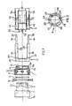
- Fig. 1 shows an exploded partially sectional side view of the control unit equipped with the fastening device according to the invention;
- Fig. 2 shows a front view of the fastening ferrule of Fig. 1;
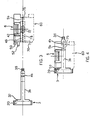
- Fig. 3 shows a second exploded side view perpendicular to the view shown in Fig. 2 of the assembled fastening ferrule and electrical unit; and
- Fig. 4 shows in the same side view of Fig. 3 the assembled fastening ferrule and electrical unit mounted together to explain the action of the securing arrangements in effect between them.
- With reference to the aforementioned figures the present control unit comprises a snap-action bayonet-type fastening device for control and/or signalling units consisting of a sleeve 1 having a partially threaded external surface, a threaded ring-nut 2 which can be screwed onto the external threaded surface of the sleeve 1 and an annular element or
engagement ferrule 3 havingflexible appendices turn teeth corresponding side protuberances electrical unit 6. Anoperative unit 7 secured to a panel 8 by means of said fastening device 1 and a washer 9 is also a part of the control unit. - The
operative unit 7 within which is mounted a movable push-button 7a indicated by dashed lines in Fig. 1 has a projecting rear portion which interacts with said fastening device and can be inserted like a bayonet and in a conventional manner in a hole of suitable form in the panel 8 and then in the sleeve 1 of the fastening device. Advantageously the external surface of a projectingportion 10 of theoperative unit 7 has L-shaped cuts orserrations 11 which engage by sliding with appropriate projections 12 which are integral with the internal surface of the sleeve 1, where the relative rotation of theoperative unit 7 with theportion 10 engagened like a bayonet in the sleeve 1 causes sliding of the projections 12 in thecuts 11 resulting in mutual engagement of the parts. The structure and operation of theoperative unit 7 of the sleeve 1 are explained better and more fully in the aforementioned EP-A-0.105.387 to which reference is made. - According to the improvements of the present invention the coupling between the
operative unit 7 and theelectrical unit 6 is accomplished by means of acoupling ferrule 3 which consist essentially ofannular frame 20 which has a shape substantially corresponding to that of an unthreadedrear portion 13 of the sleeve 1 on which saidannular frame 20 can slide axially. The unthreadedrear portion 13 has slots arranged like arcs of a circle, like theslot 14 and 14a, and protrusions, like theprotrusions corresponding protuberances slots 14 and 14a of the unthreaded portion of the sleeve, and to rotate into saidprotrusions protuberances - Said
frame 20 is then completed by anannular flange 26 which is disposed inwardly and which describes acentral hole 28 the purpose of which is to lighten said ferrule. - The two
appendices base reinforcements tongues electrical unit 6 from theappendices operative unit 7 and theelectrical unit 6 it is pointed out that saidflexible appendices longitudinal slots protuberances longitudinal side indentations electrical unit 6. - To complete the description it is noted that each
electrical unit 6 has anappendix 50 protruding frontwards from its case to engage through one of therectangular openings 24 of theferrule 3 with a corresponding longitudinal slot, not shown, present in theunthreaded portion 13 of the sleeve 1 to prevent rotation of theferrule 3 with respect to the sleeve 1 after installation of theelectrical unit 6. - If the
electrical unit 6 is a control unit, it must also have arod 52 designed to transmit a movement produced by thepushbutton 7a which is contained in theoperative unit 7 to movable elements of said electrical unit. - Together with and opposed to the electrical unit can be installed another equal or different electrical unit having control and/or signalling functions. For example the
electrical unit 60 indicated with dashed lines in Figures 3 and 4 may be a signalling unit to feed an optional lamp housed within the push-button 7a. Saidunit 60 is generally shaped in a manner similar to that of theunit 6 and in particular has anappendix 70 in all ways like theappendix 50 of theunit 6 designed to fit through anotherrectangular opening 24 of theferrule 3 into a corresponding longitudinal slot of the sleeve 1 for the purpose of helping to prevent rotation of theferrule 3 with respect to the sleeve 1 after installation of theelectrical unit 60. Saidunit 60 also has aside protuberance 75 like theprotuberance 5b, capable of engaging with thetooth 4b of theappendix 3b and aprotuberance 72 in aside indentation 76 having a longitudinal direction and being designed to engage theslot 39 of theappendix 3b (Figure 1) to ensure fastening of theunit 60 to theferrule 3.
Claims (5)
Priority Applications (1)
| Application Number | Priority Date | Filing Date | Title |
|---|---|---|---|
| AT86105561T ATE44587T1 (en) | 1985-04-24 | 1986-04-22 | LONG BAYONET-LIKE MOUNTING DEVICE FOR CONTROL AND SIGNAL UNITS. |
Applications Claiming Priority (2)
| Application Number | Priority Date | Filing Date | Title |
|---|---|---|---|
| ITMI1985U21636U IT8521636U1 (en) | 1985-04-24 | 1985-04-24 | Longitudinal snap-in fastening device for control and/or signalling units |
| IT2163685U | 1985-04-24 |
Publications (2)
| Publication Number | Publication Date |
|---|---|
| EP0199344A1 EP0199344A1 (en) | 1986-10-29 |
| EP0199344B1 true EP0199344B1 (en) | 1989-07-12 |
Family
ID=11184661
Family Applications (1)
| Application Number | Title | Priority Date | Filing Date |
|---|---|---|---|
| EP86105561A Expired EP0199344B1 (en) | 1985-04-24 | 1986-04-22 | Longitudinal snap-action fastening device for control and/or signalling units |
Country Status (5)
| Country | Link |
|---|---|
| US (1) | US4702711A (en) |
| EP (1) | EP0199344B1 (en) |
| AT (1) | ATE44587T1 (en) |
| DE (1) | DE3664362D1 (en) |
| IT (1) | IT8521636U1 (en) |
Families Citing this family (12)
| Publication number | Priority date | Publication date | Assignee | Title |
|---|---|---|---|---|
| FR2634053B1 (en) * | 1988-07-05 | 1995-06-09 | Loire Electronique | FIXING DEVICE FOR SWITCH |
| DE3828910A1 (en) * | 1988-08-26 | 1990-03-01 | Vdo Schindling | DISPLAY INSTRUMENT |
| IT219700Z2 (en) * | 1990-05-29 | 1993-04-26 | Cge Spa | CLAMPING FIXING DEVICE WITH SNAP LOCK FOR CONTROL AND / OR SIGNALING UNIT |
| US5134554A (en) * | 1990-08-30 | 1992-07-28 | Lightolier, Inc. | Lighting system |
| GB9403607D0 (en) * | 1994-02-25 | 1994-04-13 | Mk Electric Ltd | An electrical accesory mounting |
| GB2294816B (en) * | 1994-11-04 | 1998-10-07 | Lilleshall Plastics Eng | Jack socket |
| KR100424580B1 (en) * | 2001-12-20 | 2004-03-27 | 엘지전자 주식회사 | Device for locking ventilation cover to main body |
| AU2003900549A0 (en) * | 2003-02-07 | 2003-02-20 | Hager Electro S.A.S. | An assembly |
| JP4908315B2 (en) * | 2006-07-13 | 2012-04-04 | 矢崎総業株式会社 | Mounting structure |
| US7645055B2 (en) * | 2007-02-28 | 2010-01-12 | Genlyte Thomas Group, Llc | Luminaire optical assembly |
| ES2584171B1 (en) * | 2015-03-23 | 2017-04-28 | Fontini, S.A. | switch |
| JP6382245B2 (en) * | 2016-02-04 | 2018-08-29 | 株式会社豊田自動織機 | Register panel mounting structure |
Family Cites Families (10)
| Publication number | Priority date | Publication date | Assignee | Title |
|---|---|---|---|---|
| US979927A (en) * | 1909-10-06 | 1910-12-27 | Henry D Brown | Electric-light receptacle. |
| DE1500840A1 (en) * | 1966-07-22 | 1969-11-27 | Mccarthy John J | Mechanical clutch |
| FR2036116A5 (en) * | 1969-03-04 | 1970-12-24 | Telemecanique Electrique | |
| US3736011A (en) * | 1972-03-02 | 1973-05-29 | Tool & Equipment Mfg Co Inc Mo | Quick disconnect tool coupling |
| CH556982A (en) * | 1973-01-30 | 1974-12-13 | Trisa Buerstenfabrik Ag | COUPLING FOR COAXIAL PARTS, ESPECIALLY FOR HAND TOOL HANDLES. |
| CH589800A5 (en) * | 1975-04-25 | 1977-07-15 | Arx Ag | |
| US3996500A (en) * | 1975-06-16 | 1976-12-07 | Richco Plastic Company | Chassis connector and circuit board clip |
| FR2322441A1 (en) * | 1975-08-26 | 1977-03-25 | Saco Sa Anct Baumgarten Const | Electronic unit mounting system - fixes cylindrical unit with four square sectioned ribs in panel with matching grooves |
| IT8223069U1 (en) * | 1982-10-01 | 1984-04-01 | Cge Compagnia Generale Di Elett Spa | SNAP-LOCKING PLUG-IN FIXING DEVICE FOR CONTROL AND/OR SIGNALING UNITS |
| FR2541738B1 (en) * | 1983-02-28 | 1985-06-07 | Alsthom Cgee | DEVICE FOR FIXING AN OBJECT ON A WALL |
-
1985
- 1985-04-24 IT ITMI1985U21636U patent/IT8521636U1/en unknown
-
1986
- 1986-04-22 AT AT86105561T patent/ATE44587T1/en active
- 1986-04-22 EP EP86105561A patent/EP0199344B1/en not_active Expired
- 1986-04-22 DE DE8686105561T patent/DE3664362D1/en not_active Expired
- 1986-04-25 US US06/855,948 patent/US4702711A/en not_active Expired - Fee Related
Also Published As
| Publication number | Publication date |
|---|---|
| IT8521636V0 (en) | 1985-04-24 |
| US4702711A (en) | 1987-10-27 |
| DE3664362D1 (en) | 1989-08-17 |
| ATE44587T1 (en) | 1989-07-15 |
| EP0199344A1 (en) | 1986-10-29 |
| IT8521636U1 (en) | 1986-10-24 |
Similar Documents
| Publication | Publication Date | Title |
|---|---|---|
| US4702711A (en) | Snap-action bayonet-type fastening device for control and/or signalling units | |
| US5063277A (en) | Waterproof and dustproof push switch | |
| KR19990081824A (en) | Demountable connection between two housing sections | |
| EP0353929A1 (en) | Spectacles | |
| US4268108A (en) | Locking arrangement for fixing a terminal block | |
| DE19651821A1 (en) | Washing machine, etc. | |
| EP0220807A2 (en) | Retaining device for mounting electrical units | |
| US4943694A (en) | Push-button cover assembly | |
| GB2202678A (en) | A push button switch having a built-in lamp | |
| EP0080807A2 (en) | Adapter for mounting switch onto panel | |
| EP0496123B1 (en) | Switch assembly | |
| EP0694221B1 (en) | A power take-off adaptor for a conductor rail | |
| EP0898089A3 (en) | Single part fitting | |
| US5225970A (en) | Twist-in mounting for electromechanical component | |
| US5771207A (en) | Time switch | |
| US5052242A (en) | Control device for a derailleur-gear for a bicycle | |
| WO1995001664A1 (en) | Industrial-type mobile electric socket and plug of easier assembling | |
| DE3370518D1 (en) | Snap-action fastening device for control and/or signalling units | |
| AU617093B2 (en) | Improvements in/or relating to electrical switch gear | |
| US5861593A (en) | Modular switch stalk assemblable in different orientations to provide different rotation features | |
| GB2108318A (en) | Switch with a case provided with an attaching device | |
| US6320761B1 (en) | Fastening device for a housing | |
| JPH0643951Y2 (en) | Push switch attachment device | |
| WO1987004867A1 (en) | Lampholder | |
| JPH0433611Y2 (en) |
Legal Events
| Date | Code | Title | Description |
|---|---|---|---|
| PUAI | Public reference made under article 153(3) epc to a published international application that has entered the european phase |
Free format text: ORIGINAL CODE: 0009012 |
|
| AK | Designated contracting states |
Kind code of ref document: A1 Designated state(s): AT BE CH DE FR GB IT LI NL SE |
|
| 17P | Request for examination filed |
Effective date: 19870407 |
|
| 17Q | First examination report despatched |
Effective date: 19880829 |
|
| GRAA | (expected) grant |
Free format text: ORIGINAL CODE: 0009210 |
|
| AK | Designated contracting states |
Kind code of ref document: B1 Designated state(s): AT BE CH DE FR GB IT LI NL SE |
|
| REF | Corresponds to: |
Ref document number: 44587 Country of ref document: AT Date of ref document: 19890715 Kind code of ref document: T |
|
| REF | Corresponds to: |
Ref document number: 3664362 Country of ref document: DE Date of ref document: 19890817 |
|
| ET | Fr: translation filed | ||
| ITF | It: translation for a ep patent filed | ||
| PLBE | No opposition filed within time limit |
Free format text: ORIGINAL CODE: 0009261 |
|
| STAA | Information on the status of an ep patent application or granted ep patent |
Free format text: STATUS: NO OPPOSITION FILED WITHIN TIME LIMIT |
|
| 26N | No opposition filed | ||
| ITTA | It: last paid annual fee | ||
| PGFP | Annual fee paid to national office [announced via postgrant information from national office to epo] |
Ref country code: AT Payment date: 19920410 Year of fee payment: 7 |
|
| PGFP | Annual fee paid to national office [announced via postgrant information from national office to epo] |
Ref country code: NL Payment date: 19920430 Year of fee payment: 7 |
|
| PGFP | Annual fee paid to national office [announced via postgrant information from national office to epo] |
Ref country code: GB Payment date: 19920803 Year of fee payment: 7 |
|
| PG25 | Lapsed in a contracting state [announced via postgrant information from national office to epo] |
Ref country code: GB Effective date: 19930422 Ref country code: AT Effective date: 19930422 |
|
| PG25 | Lapsed in a contracting state [announced via postgrant information from national office to epo] |
Ref country code: NL Effective date: 19931101 |
|
| NLV4 | Nl: lapsed or anulled due to non-payment of the annual fee | ||
| GBPC | Gb: european patent ceased through non-payment of renewal fee |
Effective date: 19930422 |
|
| PGFP | Annual fee paid to national office [announced via postgrant information from national office to epo] |
Ref country code: BE Payment date: 19940307 Year of fee payment: 9 |
|
| PGFP | Annual fee paid to national office [announced via postgrant information from national office to epo] |
Ref country code: SE Payment date: 19940330 Year of fee payment: 9 |
|
| PGFP | Annual fee paid to national office [announced via postgrant information from national office to epo] |
Ref country code: CH Payment date: 19940728 Year of fee payment: 9 |
|
| EAL | Se: european patent in force in sweden |
Ref document number: 86105561.4 |
|
| PG25 | Lapsed in a contracting state [announced via postgrant information from national office to epo] |
Ref country code: SE Effective date: 19950423 |
|
| PG25 | Lapsed in a contracting state [announced via postgrant information from national office to epo] |
Ref country code: CH Effective date: 19950430 Ref country code: LI Effective date: 19950430 Ref country code: BE Effective date: 19950430 |
|
| BERE | Be: lapsed |
Owner name: CGE- COMPAGNIA GENERALE ELETTROMECCANICA S.P.A. Effective date: 19950430 |
|
| REG | Reference to a national code |
Ref country code: CH Ref legal event code: PL |
|
| EUG | Se: european patent has lapsed |
Ref document number: 86105561.4 |
|
| PGFP | Annual fee paid to national office [announced via postgrant information from national office to epo] |
Ref country code: FR Payment date: 20030212 Year of fee payment: 18 |
|
| PGFP | Annual fee paid to national office [announced via postgrant information from national office to epo] |
Ref country code: DE Payment date: 20030430 Year of fee payment: 18 |
|
| PG25 | Lapsed in a contracting state [announced via postgrant information from national office to epo] |
Ref country code: DE Free format text: LAPSE BECAUSE OF NON-PAYMENT OF DUE FEES Effective date: 20041103 |
|
| PG25 | Lapsed in a contracting state [announced via postgrant information from national office to epo] |
Ref country code: FR Free format text: LAPSE BECAUSE OF NON-PAYMENT OF DUE FEES Effective date: 20041231 |
|
| REG | Reference to a national code |
Ref country code: FR Ref legal event code: ST |
|
| PG25 | Lapsed in a contracting state [announced via postgrant information from national office to epo] |
Ref country code: IT Free format text: LAPSE BECAUSE OF NON-PAYMENT OF DUE FEES;WARNING: LAPSES OF ITALIAN PATENTS WITH EFFECTIVE DATE BEFORE 2007 MAY HAVE OCCURRED AT ANY TIME BEFORE 2007. THE CORRECT EFFECTIVE DATE MAY BE DIFFERENT FROM THE ONE RECORDED. Effective date: 20050422 |