EP0198402A2 - Lager mit vollautomatischer Ein- und Auslagerung von Lagerartikeln - Google Patents
Lager mit vollautomatischer Ein- und Auslagerung von Lagerartikeln Download PDFInfo
- Publication number
- EP0198402A2 EP0198402A2 EP86104819A EP86104819A EP0198402A2 EP 0198402 A2 EP0198402 A2 EP 0198402A2 EP 86104819 A EP86104819 A EP 86104819A EP 86104819 A EP86104819 A EP 86104819A EP 0198402 A2 EP0198402 A2 EP 0198402A2
- Authority
- EP
- European Patent Office
- Prior art keywords
- storage
- identification code
- identification
- machine
- control
- Prior art date
- Legal status (The legal status is an assumption and is not a legal conclusion. Google has not performed a legal analysis and makes no representation as to the accuracy of the status listed.)
- Granted
Links
Images

Classifications
-
- G—PHYSICS
- G06—COMPUTING; CALCULATING OR COUNTING
- G06Q—INFORMATION AND COMMUNICATION TECHNOLOGY [ICT] SPECIALLY ADAPTED FOR ADMINISTRATIVE, COMMERCIAL, FINANCIAL, MANAGERIAL OR SUPERVISORY PURPOSES; SYSTEMS OR METHODS SPECIALLY ADAPTED FOR ADMINISTRATIVE, COMMERCIAL, FINANCIAL, MANAGERIAL OR SUPERVISORY PURPOSES, NOT OTHERWISE PROVIDED FOR
- G06Q10/00—Administration; Management
- G06Q10/08—Logistics, e.g. warehousing, loading or distribution; Inventory or stock management
-
- B—PERFORMING OPERATIONS; TRANSPORTING
- B65—CONVEYING; PACKING; STORING; HANDLING THIN OR FILAMENTARY MATERIAL
- B65G—TRANSPORT OR STORAGE DEVICES, e.g. CONVEYORS FOR LOADING OR TIPPING, SHOP CONVEYOR SYSTEMS OR PNEUMATIC TUBE CONVEYORS
- B65G1/00—Storing articles, individually or in orderly arrangement, in warehouses or magazines
- B65G1/02—Storage devices
- B65G1/04—Storage devices mechanical
- B65G1/137—Storage devices mechanical with arrangements or automatic control means for selecting which articles are to be removed
- B65G1/1371—Storage devices mechanical with arrangements or automatic control means for selecting which articles are to be removed with data records
Definitions
- the invention relates to a warehouse with fully automatic storage and retrieval of storage items of the type defined in the preamble of claim 1.
- a warehouse management computer determines the optimal storage location address for a mobile storage unit receiving one or more storage items, taking into account the nature of the item, the short travel time of the storage machine and the avoidance of storing the same items in the same storage aisle.
- This optimized storage location address is assigned to the respective storage unit and at the same time communicated to the control device for the storage machine.
- the addressed storage unit is then transferred from an operator at an entry point to a clock-controlled conveyor belt system comprising a plurality of sub-belts and is fed by this to one of the storage machines.
- the storage machine then sets the storage unit accordingly according to the address specification in the control device at the addressed storage location.
- the invention is based on the object of taking measures in a bearing of the type mentioned at the outset which ensure detection of the described errors during storage, so that these can be recognized and corrected at an early stage.
- the bearing according to the invention has the advantage that due to the individual identification codes assigned to the mobile storage units by means of the identification reading device outside the storage processing time, e.g. B. at night, an actual stock of the stored storage units can be recorded in assignment to the storage bins.
- This In the comparison unit the actual stock is compared with the target warehouse stock created by the warehouse management computer by address assignment and identification code assignment, and incorrect storage of warehouse units is thus determined immediately.
- This incorrect storage can - since it is usually only a few - without problems, e.g. B. by outsourcing and re-identification.
- the bearing according to the invention it is thus possible to continuously monitor the entire storage system, that is to say both the warehouse management and the bearing mechanics with control systems. All errors that have crept in at any interface during the storage of warehouse items are fully recorded at the latest during the inventory check carried out with the identification code reading device according to the invention.
- the warehouse according to the invention is thus characterized by an extremely high level of administration and access security. In particular, errors in the bearing occupancy are already recognized in the filling phase of the bearing, so that a reliably correctly occupied bearing is available when the bearing starts operating.
- An advantageous embodiment of the invention results from claim 2.
- the reading device can be permanently installed on the storage machine.
- the reading device can be placed on the storage machine like a storage unit, so that only one reading device is required even in the case of several storage machines.
- the reading device can be set up or moved by hand.
- automatic control of the reading device via the conveyor belt system is also possible, which can be done in almost the same way as control of a mobile storage unit.
- the warehouse shown schematically in Fig. 1 has a plurality of storage spaces 10, which are assembled into a high rack 11. Each storage location 10 is clearly defined by a permanently assigned storage location address.
- a storage machine 12 In front of the high rack 11, a storage machine 12 is installed, which in horizontal and Is vertically movable and carries a gripper, not shown, for moving into the individual storage bins 10.
- the storage machine 12 is controlled by a control device 13 connected to it via a control line 32 in such a way that it visits the respective storage location 10 with a matching storage location address on the basis of storage location address specifications and there, upon a corresponding control command, a storage or retrieval of a storage unit 14 by means of it Grabs.
- a maximum of one mobile storage unit 14 can be stored at each storage location 10.
- the mobile storage units 14 can be designed as containers, pallets or other receptacles. All bearing units l4 have the same dimensions. A different number of storage items, depending on their size, can be inserted in each storage unit 14.
- a large number of high racks 11 and a plurality of storage machines 12 are usually present in the warehouse, one storage machine 12 in each case being movable in an aisle between two high racks 11 and serving these two high racks 11.
- the conveyor belt 16 is then part of a clock-controlled belt system.
- the entire control of the warehouse is carried out by a central warehouse management computer 17, which is shown in the block diagram only to the extent of interest here.
- An essential part of the computer 17 is, in addition to a control block 18 for triggering the individual control commands, an addressing device 19 which assigns a storage location address in the high rack 11 to a storage unit 14 to be inserted at the entry point 15 of the storage.
- This storage location address is selected on the basis of the existing storage allocation from the point of view of optimization, such as the nature of the articles contained in the storage unit, short transport routes, access security, etc., and is communicated to the control device 13.
- the addressing device 19 works together with an identification device 20, by means of which the loaded storage units 14 are identified at the entry point 15 before being transferred to the conveyor belt 16.
- the identification device 20 either outputs an identification code which, for. B. is attached to the storage unit 14 as a machine-readable sticker, or identifies a storage unit 14 already provided with such an identification code.
- the predetermined or read identification code is output by the identification device 20 and on the one hand the addressing device 19 for optimizing the storage space address assignment and on the other hand fed to a first memory 21.
- This memory 21 is also connected to the addressing device 19, as a result of which the storage location address assigned to the identified storage unit 14 is also supplied.
- the data output of the first memory 21 is connected to a first input of a comparison unit 22, the second input of which is led out of the computer 17 and is designed as a connection socket 23.
- the output of the comparison unit 22 is connected to an error display 24.
- the high rack 11 with its storage spaces 10 is assigned an identification code reading device 25 which can be controlled independently of the addressing device 19 in such a way that, starting from a specified storage space 10, it searches for all other storage spaces in a predetermined sequence and in each case the identity codes of those stored in the storage spaces 10 Reads storage units 14.
- the outermost storage location 10 in the lowest or uppermost row of shelves is expediently selected as the starting point for the control movement of the reading device 25 and the reading device 25 is controlled from storage location 10 to storage location 10 in a sequence predetermined according to the aspects of the shortest path.
- the identification codes read at the individual storage locations 10 by the reading device 25 from the storage units 14 stored there are stored in a second memory 26 connected to the reading device 25 in association with the storage locations.
- the output of the second memory 26 is connected to the connection socket 23 of the comparison unit 22.
- the comparison unit 22 now compares the identification codes of the same storage location assignment If the two memories 21, 26 do not match, there is an incorrect or incorrect assignment.
- the comparison unit 22 then controls the error display 24, and this indicates the incorrect assignment visibly.
- the identification code reading device 25 and the second memory 26 in a housing 27 and to place this as a mobile part on the storage machine 12 manually or automatically.
- the control of the reading device 25 in the manner described from storage location 10 to storage location 10 is then carried out by corresponding control of the storage machine 12.
- a button 28 "warehouse control" is manual to operate.
- the control block 18 then triggers the predetermined control program, in which the. Control device 13 and a second control line 29 to the storage machine 12 the latter visits a storage location 10, for. B. the outermost upper storage bin in the high rack 11, and then gradually controls the adjacent storage bin 10.
- the first control line 32 for address control between the control device 13 and the storage machine 12 is then blocked.
- the identification code reading device 25 is positioned on the storage machine 12 so that it can read the identification code of a storage unit 14 possibly stored in the storage space 12 in each storage location position of the storage machine 12.
- the identification codes read are stored in the second memory 26 as described.
- the order of storage corresponds to the order of the controlled storage bins 10 in the high-bay warehouse 11, so that an unambiguous identification code storage location assignment is guaranteed.
- a separate control unit 30 'for controlling the bearing machine 12' is provided in the housing 27 'during the bearing control phase.
- the control line 32 'of the storage machine 12' is separated from the control device 13 and connected to the control unit 30 '.
- the control unit 30 ' controls the storage machine 12' in the same way as described above.
- a position indicator 31 ' is also arranged in the housing 27', which detects an exact position of the bearing machine 12 'on the individual bearings places 12 detected and a feedback pulse to the control unit 30 'and possibly a write command to the second memory 26'.
- a position detector 31 'can, for. B. be designed as a photoelectric scanner that interacts with reflection surfaces on the high rack 11, which are each spatially assigned to a storage location 10.
- the vertical shelf struts of the high rack 11 can be used as reflection surfaces, for example.
- storage spaces are usually served by a storage machine, which are arranged on both sides of a storage aisle to oppose high racks.
- the identification code reading device - and the second memory connected to it - are duplicated in this case, so that each time the storage machine is positioned during the inventory control process, the identification codes of stored storage units are read in separately at two opposite storage locations and saved.
Abstract
Description
- Die Erfindung betrifft ein Lager mit vollautomatischer Ein- und Auslagerung von Lagerartikeln der im Oberbegriff des Anspruchs 1 definierten Gattung.
- Bei einem bekannten Lager dieser Art werden alle Lagerbewegungen von einem Lagerverwaltungsrechner zentral gesteuert, wobei sowohl die Einlagerung als auch die Auslagerung von Lagerartikeln unter Optimierungsgesichtspunkten erfolgt. Zum Beispiel ermittelt die einen Teil des Lagerverwaltungsrechners bildende Adressiereinrichtung die optimale Lagerplatzadresse für eine einen oder mehrere Lagerartikel aufnehmende mobile Lagereinheit unter den Gesichtspunkten der Artikelbeschaffenheit, der kurzen Fahrzeit der Lagermaschine und der Vermeidung der Einlagerung gleicher Artikel in der gleichen Lagerplatzgasse. Diese optimierte Lagerplatzadresse wird der jeweiligen Lagereinheit zugewiesen und gleichzeitig der Steuervorrichtung für die Lagermaschine mitgeteilt. Die. adressierte Lagereinheit wird dann an einer Eintrittsstelle von einer Bedienungsperson an ein taktgesteuertes Transportbandsystem aus mehreren Teilbändern übergeben und von diesem einer der Lagermaschinen zugeführt. Die Lagermaschine legt dann die Lagereinheit entsprechend der Adressenvorgabe in der Steuervorrichtung an dem adressierten Lagerplatz ab.
- Durch die Komplexität dieses Verwaltungs- und Transportsystems mit seinen zahlreichen Schnittstellen ist es möglich, daß eine Diskrepanz zwischen dem im Lagerverwaltungssystem abgespeicherten Lagerplatz eines Lagerartikels und dem tatsächlichen physischen Lagerplatz entsteht. Solche Fehler können durch Bedienfehler (Vertauschen zweier Lagereinheiten an der Eintrittsstelle), durch unsachgemäße Reaktion auf Fehlermeldungen, durch Steuerfehler in den Transportsystemen selbst etc. hervorgerufen werden. Solche Fehler bewirken eine partielle Falschbelegung des Lagers, was langfristig zu einem totalen Zusammenbruch des gesamten Lagerverwaltungssystems führen kann.
- Der Erfindung liegt die Aufgabe zugrunde, in einem Lager der eingangs genannten Art Maßnahmen zu treffen, die eine Erkennung der beschriebenen Fehler bereits bei der Einlagerung sicherstellen, so daß diese frühzeitig erkannt und korrigiert werden können.
- Die Aufgabe ist bei einem Lager der im Oberbegriff des Anspruchs 1 angegebenen Gattung durch die Merkmale im Kennzeichenteil des Anspruchs 1 gelöst.
- Das erfindungsgemäße Lager hat den Vorteil, daß aufgrund der den mobilen Lagereinheiten zugeordneten individuellen Identifikationscodes mittels der Identifikations-Lesevorrichtung außerhalb der Lagerbearbeitungszeit, z. B. in den Nachtstunden, ein Istbestand der eingelagerten Lagereinheiten in Zuordnung zu den Lagerplätzen aufgenommen werden kann. Dieser Istbestand wird in der Vergleichseinheit mit dem vom Lagerverwaltungsrechner durch Adressenzuweisung und Identifikationscode-Vergabe erstellten Lagersollbestand verglichen und somit Fehleinlagerungen von Lagereinheiten unmittelbar festgestellt. Diese Fehleinlagerungen können - da es sich meist nur um wenige handelt - problemlos, z. B. durch Auslagerung und Neuidentifikation, beseitigt werden.
- Bei dem erfindungsgemäßen Lager ist somit eine laufende Kontrolle des gesamten Lagersystems, also sowohl der Lagerverwaltung als auch der Lagermechanik mit Steuersystemen, möglich. Alle Fehler, die sich bei der Einlagerung von Lagerartikeln an irgendeiner Schnittstelle eingeschlichen haben, werden spätestens bei der mit der erfindungsgemäßen Identifikationscode-Lesevorrichtung durchgeführten Lagerbestandskontrolle vollständig erfaßt. Das erfindungsgemäße Lager zeichnet sich somit durch eine extrem hohe Verwaltungs- und Zugriffssicherheit aus. Insbesondere werden Fehler in der Lagerbelegung bereits in der Füllphase des Lagers erkannt, so daß bei Aufnahme des Lagerbetriebs ein zuverlässig richtig belegtes Lager zur Verfügung steht.
- Eine vorteilhafte Ausführungsform der Erfindung ergibt sich aus Anspruch 2. Durch Ausnutzen der in gleicher Weise steuerbaren Lagermaschine kann ein separates Antriebs- und Steuergetriebe für die Identifikationscode-Lesevorrichtung eingespart werden. Die Lesevorrichtung kann dabei an der Lagermaschine fest installiert sein. Bei mehreren Lagermaschinen, von denen jeweils eine einer Lagerplatzgasse zugeordnet ist und die dort liegenden Lagerplätze bedient, ist es zweckmäßig, die Lesevorrichtung wie eine Lagereinheit auf die Lagermaschine aufzusetzen, so daß auch bei mehreren Lagermaschinen nur eine Lesevorrichtung erforderlich ist. Die Lesevorrichtung kann dabei von Hand auf- oder umgesetzt werden. Möglich ist aber auch eine automatische Einsteuerung der Lesevorrichtung über das Transportbandsystem, was in nahezu identischer Weise wie die Einsteuerung einer mobilen Lagereinheit erfolgen kann.
- Die Erfindung ist anhand von in der Zeichnung dargestellten Ausführungsbeispielen im folgenden näher beschrieben.
- Es zeigen jeweils in schematischer Darstellung:
- Fig. 1 eine Draufsicht eines Lagers mit zentralem Lagerverwaltungsrechner und Identifikationsvorrichtung im Blockschaltbild,
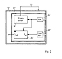
- Fig. 2 eine Draufsicht einer Lagermaschine mit aufgesetztem Gehäuse und darin installierter Identifikationscode-Lesevorrichtung, Speicher und Steuereinheit.
- Das in Fig. 1 schematisch dargestellte Lager weist eine Vielzahl von Lagerplätzen 10 auf, die zu einem Hochregal 11 zusammengesetzt sind. Jeder Lagerplatz 10 ist durch eine fest zugeordnete Lagerplatzadresse eindeutig definiert. Vor dem Hochregal 11 ist eine Lagermaschine 12 installiert, die in Horizontal- und Vertikalrichtung verfahrbar ist und einen nicht dargestellten Greifer zum Einfahren in die einzelnen Lagerplätze 10 trägt. Die Lagermaschine 12 wird von einer mit ihr über eine Steuerleitung 32 verbundene Steuervorrichtung 13 derart gesteuert, daß sie aufgrund von Lagerplatzadressen-Vorgaben den jeweiligen Lagerplatz 10 mit übereinstimmender Lagerplatzadresse aufsucht und dort auf einen entsprechenden Steuerbefehl hin eine Ein- oder Auslagerung einer Lagereinheit l4 mittels ihres Greifers vornimmt.
- An jedem Lagerplatz 10 kann maximal eine mobile Lagereinheit l4 eingelagert werden. Die mobilen Lagereinheiten 14 können als Behälter, Paletten oder sonstige Aufnahmebehältnisse ausgebildet sein. Alle Lagereinheiten l4 weisen gleiche Abmessungen auf. In jeder Lagereinheit l4 kann eine unterschiedliche Anzahl von Lagerartikeln, je nach deren Größe, eingelegt werden. Zur Einbringung von Lagerartikeln in das Lager werden die Lagerartikel in Lagereinheiten 14 eingelegt und die Lagereinheiten 14 an einer Eintrittsstelle 15 - auch I-Punkt des Lagers genannt - einem Transportband 16 übergeben, das seinerseits die Lagereinheiten 14 der Lagermaschine 12 zuführt. Diese nimmt mit ihrem Greifer die jeweilige Lagereinheit 14 vom Transportband 16 und legt diese in dem vorgegebenen Lagerplatz 10 im Hochregal 11 ab. Üblicherweise sind im Lager eine Vielzahl von Hochregalen 11 und eine Mehrzahl von Lagermaschinen 12 vorhanden, wobei jeweils eine Lagermaschine 12 in einer Gasse zwischen zwei Hochregalen 11 verfahrbar ist und diese beiden Hochregale 11 bedient. Das Transportband 16 ist dann Teil eines taktgesteuerten Bandsystems.
- Die gesamte Steuerung des Lagers wird von einem zentralen Lagerverwaltungsrechner 17 durchgeführt, der nur in dem hier interessierenden Umfang im Blockschaltbild dargestellt ist. Wesentlicher Teil des Rechners 17 ist neben einem Steuerblock 18 zur Auslösung der einzelnen Steuerbefehle eine Adressiereinrichtung 19, welche einer an der Eintrittsstelle 15 des Lagers einzuschiebenden Lagereinheit 14 eine Lagerplatzadresse im Hochregal 11 zuweist. Diese Lagerplatzadresse wird aufgrund der vorhandenen Lagerbelegung unter Optimierungsgesichtspunkten, wie Beschaffenheit der in der Lagereinheit enthaltenen Artikel, kurzen Transportwege, Zugriffssicherheit etc. ausgewählt und der Steuervorrichtung 13 mitgeteilt.
- Die Adressiereinrichtung 19 arbeitet mit einer Identifikationsvorrichtung 20 zusammen, mittels welcher die beladenen Lagereinheiten 14 an der Eintrittsstelle 15 vor Übergabe an das Transportband 16 identifiziert werden. Die Identifikationsvorrichtung 20 gibt dabei entweder einen Identifikationscode aus, der z. B. als maschinell lesbarer Aufkleber an der Lagereinheit l4 befestigt wird, oder identifiziert eine bereits mit einem solchen Identifikationscode versehene Lagereinheit 14. In beiden Fällen wird der vorgegebene oder ausgelesene Identifikationscode von der Identifikationsvorrichtung 20 ausgegeben und einerseits der Adressiereinrichtung 19 zur Optimierung der Lagerplatzadressenzuweisung und andererseits einem ersten Speicher 21 zugeführt. Dieser Speicher 21 ist außerdem mit der Adressiereinrichtung 19 verbunden, wodurch diesem auch die der identifizierten Lagereinheit 14 zugewiesene Lagerplatzadresse zugeführt wird. Im Speicher 21 werden damit die Identifikationscodes aller in das Hochregal 11 eingelagerten Lagereinheiten 14 in Zuordnung zu den zugewiesenen Lagerplatzadressen abgespeichert. Der Datenausgang des ersten Speichers 21 ist mit einem ersten Eingang einer Vergleichseinheit 22 verbunden, deren zweiter Eingang aus dem Rechner 17 herausgeführt und als Anschlußbuchse 23 ausgebildet ist. Der Ausgang der Vergleichseinheit 22 ist mit einer Fehleranzeige 24 verbunden.
- Dem Hochregal 11 mit seinen Lagerplätzen 10 ist eine Identifikationscode-Lesevorrichtung 25 zugeordnet, die unabhängig von der Adressiereinrichtung 19 derart steuerbar ist, daß sie ausgehend von einem vorgegebenen Lagerplatz 10 alle weiteren Lagerplätze in vorgegebener Reihenfolge aufsucht und jeweils die Identitätscodes der in den Lagerplätzen 10 eingelagerten Lagereinheiten 14 ausliest. Zweckmäßigerweise wird dabei als Ausgangspunkt für die Steuerbewegung der Lesevorrichtung 25 der äußerste Lagerplatz 10 in der untersten oder obersten Regalreihe gewählt und die Lesevorrichtung 25 in einer nach den Gesichtspunkten der kürzesten Wegstrecke vorgegebenen Reihenfolge von Lagerplatz 10 zu Lagerplatz 10 gesteuert. Die an den einzelnen Lagerplätzen 10 durch die Lesevorrichtung 25 von den dort eingelagerten Lagereinheiten 14 abgelesenen Identifikationscodes werden in einem mit der Lesevorrichtung 25 verbundenen zweiten Speicher 26 in Zuordnung zu den Lagerplätzen abgespeichert. Nach kompletter Abtastung aller Lagerplätze 10 wird der Ausgang des zweiten Speichers 26 mit der Anschlußbuchse 23 der Vergleichseinheit 22 verbunden. Die Vergleichseinheit 22 vergleicht nunmehr die Identifikationscodes gleicher Lagerplatzzuordnungen in den beiden Speichern 21, 26. Stimmen diese nicht überein, so ist eine Fehl- oder Falschbelegung vorhanden. Die Vergleichseinheit 22 steuert dann die Fehleranzeige 24 an, und diese weist die Falschbelegung sichtbar aus.
- Durch die beschriebene Aufnahme des tatsächlichen Istbestandes an Lagereinheiten l4 in Zuordnung zu den Lagerplätzen 10 mit Hilfe der Identifikationscode-Lesevorrichtung 25 und durch den anschließenden Vergleich des Istbestandes mit dem an der Eintrittsstelle 15 des Lagers vorgegebenen Sollbestand mit Hilfe der Vergleichseinheit 25 wird jeder Einlagerungsfehler, unabhängig wodurch und an welcher Stelle er bewirkt worden ist, sofort festgestellt. Damit werden Fehler im Gesamtsystem bereits beim Füllen des Lagers erkennbar und nicht erst im späteren Betrieb aufgrund von Auslagere gen bzw. Rücklagerungen der Lagereinheiten 14. Diese beschriebene Lagerkontrolle wird zweckmäßigerweise in Zeitintervallen durchgeführt, in denen keine Lagerbewegungen erfolgen. also z. B. in den Nachtstunden.
- Wie in Fig. 1 schematisch angedeutet ist, ist es aus Kostengründen zweckmäßig, die Identifikationscode-Lesevorrichtung 25 und den zweiten Speicher 26 in einem Gehäuse 27 unterzubringen und dieses als mobiles Teil auf die Lagermaschine 12 manuell oder automatisch aufzusetzen. Die Steuerung der Lesevorrichtung 25 in der beschriebenen Weise von Lagerplatz 10 zu Lagerplatz 10 erfolgt dann durch entsprechende Steuerung der Lagermaschine 12. Zur Auslösung des beschriebenen Lagerbestandskontrollvorgangs ist eine Taste 28 "Lagerkontrolle" manuell zu betätigen. Der Steuerblock 18 löst dann das vorgegebene Steuerprogramm aus, bei welchem über die. Steuervorrichtung 13 und eine zweite Steuerleitung 29 zur Lagermaschine 12 letztere einen Lagerplatz 10 aufsucht, z. B. den äußersten oberen Lagerplatz im Hochregal 11, und dann schrittweise den jeweils benachbarten Lagerplatz 10 ansteuert. Die erste Steuerleitung 32 für die Adressensteuerung zwischen Steuervorrichtung 13 und Lagermaschine 12 ist dann gesperrt. Die Identifikationscode-Lesevorrichtung 25 ist dabei auf der Lagermaschine 12 so positioniert, daß sie in jeder Lagerplatzposition der Lagermaschine 12 den Identifikationscode einer im Lagerplatz 12 evtl. eingelagerten Lagereinheit 14 abzulesen vermag. Die gelesenen Identifikationscodes werden in dem zweiten Speicher 26, wie beschrieben, abgespeichert. Die Reihenfolge der Abspeicherung entspricht der Reihenfolge der angesteuerten Lagerplätze 10 im Hochregallager 11, so daß eine eindeutige Identifikationscode-Lagerplatz-Zuordnung gewährleistet ist.
- In dem in Fig. 2 dargestellten weiteren Ausführungsbeispiel ist in dem Gehäuse 27' noch eine separate Steuereinheit 30' zur Steuerung der Lagermaschine 12' während der Lagerkontrollphase vorgesehen. In diesem Fall wird die Steuerleitung 32' der Lagermaschine 12' zu der Steuervorrichtung 13 getrennt und an die Steuereinheit 30' angeschlossen. Die Steuereinheit 30' steuert die Lagermaschine 12' in der gleiche Weise wie vorstehend beschrieben.
- Zur Erhöhung der Aufzeichnungssicherheit beim Lagerkontrollvorgang ist in dem Gehäuse 27' noch ein Positionsmelder 31' angeordnet, der eine exakte Position der Lagermaschine 12' an den einzelnen Lagerplätzen 12 detektiert und einen Rückmeldeimpuls an die Steuereinheit 30' und ggf. einen Einschreibbefehl an den zweiten Speicher 26' gibt. Ein solcher Positionsmelder 31' kann z. B. als fotoelektrischer Abtaster ausgebildet sein, der mit Reflexionsflächen am Hochregal 11, die jeweils einem Lagerplatz 10 räumlich zugeordnet sind, zusammenwirkt. Als Reflexionsflächen können z.B. die vertikalen Regalstreben des Hochregals 11 Verwendung finden.
- Wie eingangs erwähnt, werden üblicherweise von einer Lagermaschine Lagerplätze bedient, die beiderseits einer Lagergasse zu einander gegenüberliegenden Hochregalen zusammengestellt sind. Um hier die Zeit für die Lagerbestandskontrolle zu verkürzen, werden in diesem Fall die Identifikationscode-Lesevorrichtung - und der mit dieser verbundene zweiter Speicher dupliziert, so daß bei jeder Positionierung der Lagermaschine während des Lagerbestandskontrollvorgang gleichzeitig an zwei zueinander gegenüberliegenden Lagerplätzen die Identifikationscodes eingelagerter Lagereinheiten getrennt eingelesen und abgespeichert werden.
Claims (5)
Priority Applications (1)
| Application Number | Priority Date | Filing Date | Title |
|---|---|---|---|
| AT86104819T ATE38504T1 (de) | 1985-04-18 | 1986-04-09 | Lager mit vollautomatischer ein- und auslagerung von lagerartikeln. |
Applications Claiming Priority (2)
| Application Number | Priority Date | Filing Date | Title |
|---|---|---|---|
| DE3513959 | 1985-04-18 | ||
| DE19853513959 DE3513959A1 (de) | 1985-04-18 | 1985-04-18 | Lager mit vollautomatischer ein- und auslagerung von lagerartikeln |
Publications (3)
| Publication Number | Publication Date |
|---|---|
| EP0198402A2 true EP0198402A2 (de) | 1986-10-22 |
| EP0198402A3 EP0198402A3 (en) | 1987-07-01 |
| EP0198402B1 EP0198402B1 (de) | 1988-11-09 |
Family
ID=6268424
Family Applications (1)
| Application Number | Title | Priority Date | Filing Date |
|---|---|---|---|
| EP86104819A Expired EP0198402B1 (de) | 1985-04-18 | 1986-04-09 | Lager mit vollautomatischer Ein- und Auslagerung von Lagerartikeln |
Country Status (3)
| Country | Link |
|---|---|
| EP (1) | EP0198402B1 (de) |
| AT (1) | ATE38504T1 (de) |
| DE (2) | DE3513959A1 (de) |
Cited By (8)
| Publication number | Priority date | Publication date | Assignee | Title |
|---|---|---|---|---|
| EP0349433A1 (de) * | 1988-07-01 | 1990-01-03 | SOCIETE GENERALE POUR LES TECHNIQUES NOUVELLES S.G.N. Société anonyme dite: | Verfahren und Einrichtung zum Steuern von Lagern |
| AU597193B1 (en) * | 1987-04-22 | 1990-05-24 | Outboard Marine Corporation | Apparatus and method for parts assembly |
| EP0431823A1 (de) * | 1989-12-02 | 1991-06-12 | Sumitomo Rubber Industries Limited | Verfahren und Vorrichtung zum Ein- und Auslagern von Artikeln |
| EP0466004A1 (de) * | 1990-07-10 | 1992-01-15 | Daifuku Co., Ltd. | Steuerungssystem für automatische Warenhauseinrichtungen |
| GB2251241A (en) * | 1991-01-18 | 1992-07-01 | Johnson Brothers Developments | A warehouse control apparatus |
| DE19838319A1 (de) * | 1998-08-24 | 2000-03-09 | Quelle Schickedanz Ag & Co | Verfahren zum Behandeln von Artikeln im Versandhandel |
| DE102004035819B4 (de) * | 2004-07-23 | 2009-05-28 | Dematic Gmbh | Verfahren zur automatischen Lagerguterfassung in einem Warenlager |
| WO2015107313A1 (fr) * | 2014-01-17 | 2015-07-23 | Scallog | Système de gestion d'un entrepôt pour la préparation de commandes et son procédé de mise en oeuvre |
Citations (1)
| Publication number | Priority date | Publication date | Assignee | Title |
|---|---|---|---|---|
| US4219296A (en) * | 1977-03-15 | 1980-08-26 | Itoki Kosakusho Co., Ltd. | Automatic storage and retrieval apparatus for individual file folders |
-
1985
- 1985-04-18 DE DE19853513959 patent/DE3513959A1/de not_active Withdrawn
-
1986
- 1986-04-09 EP EP86104819A patent/EP0198402B1/de not_active Expired
- 1986-04-09 DE DE8686104819T patent/DE3661134D1/de not_active Expired
- 1986-04-09 AT AT86104819T patent/ATE38504T1/de not_active IP Right Cessation
Patent Citations (1)
| Publication number | Priority date | Publication date | Assignee | Title |
|---|---|---|---|---|
| US4219296A (en) * | 1977-03-15 | 1980-08-26 | Itoki Kosakusho Co., Ltd. | Automatic storage and retrieval apparatus for individual file folders |
Cited By (13)
| Publication number | Priority date | Publication date | Assignee | Title |
|---|---|---|---|---|
| AU597193B1 (en) * | 1987-04-22 | 1990-05-24 | Outboard Marine Corporation | Apparatus and method for parts assembly |
| US5175690A (en) * | 1988-07-01 | 1992-12-29 | Societe Generale Pour Les Techniques Nouvelles-S.G.N. | Process for managing stores and device for carrying it out |
| FR2633595A1 (fr) * | 1988-07-01 | 1990-01-05 | Sgn Soc Gen Tech Nouvelle | Procede de gestion de magasins |
| EP0349433A1 (de) * | 1988-07-01 | 1990-01-03 | SOCIETE GENERALE POUR LES TECHNIQUES NOUVELLES S.G.N. Société anonyme dite: | Verfahren und Einrichtung zum Steuern von Lagern |
| EP0431823A1 (de) * | 1989-12-02 | 1991-06-12 | Sumitomo Rubber Industries Limited | Verfahren und Vorrichtung zum Ein- und Auslagern von Artikeln |
| EP0466004A1 (de) * | 1990-07-10 | 1992-01-15 | Daifuku Co., Ltd. | Steuerungssystem für automatische Warenhauseinrichtungen |
| GB2251241A (en) * | 1991-01-18 | 1992-07-01 | Johnson Brothers Developments | A warehouse control apparatus |
| GB2251241B (en) * | 1991-01-18 | 1994-04-27 | Johnson Brothers Developments | A warehouse control apparatus |
| DE19838319A1 (de) * | 1998-08-24 | 2000-03-09 | Quelle Schickedanz Ag & Co | Verfahren zum Behandeln von Artikeln im Versandhandel |
| DE19838319B4 (de) * | 1998-08-24 | 2006-11-23 | Quelle Neckermann Logistik Gmbh | Verfahren zum Behandeln von Artikeln im Versandhandel |
| DE102004035819B4 (de) * | 2004-07-23 | 2009-05-28 | Dematic Gmbh | Verfahren zur automatischen Lagerguterfassung in einem Warenlager |
| WO2015107313A1 (fr) * | 2014-01-17 | 2015-07-23 | Scallog | Système de gestion d'un entrepôt pour la préparation de commandes et son procédé de mise en oeuvre |
| FR3016718A1 (fr) * | 2014-01-17 | 2015-07-24 | Scallog | Systeme de gestion d'un entreprot pour la preparation de commandes et son procede de mise en oeuvre |
Also Published As
| Publication number | Publication date |
|---|---|
| DE3513959A1 (de) | 1986-10-30 |
| ATE38504T1 (de) | 1988-11-15 |
| DE3661134D1 (en) | 1988-12-15 |
| EP0198402A3 (en) | 1987-07-01 |
| EP0198402B1 (de) | 1988-11-09 |
Similar Documents
| Publication | Publication Date | Title |
|---|---|---|
| DE4015935C2 (de) | Kommissioniervorrichtung für Artikel | |
| EP1812321B1 (de) | Warenumschlaglager und verfahren zu dessen betrieb | |
| EP2421774B1 (de) | Lager- und kommissioniersystem und verfahren zum betreiben desselben im batch-betrieb | |
| DE112006001872B4 (de) | Kommissionierverfahren sowie Kommissionierfördervorrichtung für ein Lager | |
| EP1598291B1 (de) | Verfahren und Vorrichtung zur automatisierten Einlagerung von Waren | |
| EP3265406B1 (de) | Verfahren zum einlagern von stückgütern in ein lagerregal und lagersystem | |
| EP2173644B1 (de) | System und verfahren zum handling von retourwaren in eine kommissionieranlage | |
| EP2186754B1 (de) | Kommissionieranlage und Verfahren zum Betreiben derselben mit einem Kommissionierwagen | |
| DE10136354A1 (de) | Verfahren und Anlage zum Kommissionieren mit einem Behälterregal und zugeordnetem Regalbediengerät | |
| EP0847939B1 (de) | Verfahren und Vorrichtung zum Kommissionieren | |
| DE4233688A1 (de) | Lagerregal | |
| EP1243349A1 (de) | Verfahren und Vorrichtung zur Befüllung und zum automatischen Abtransport von Sortiergutaufnahmebehältern | |
| EP0198402B1 (de) | Lager mit vollautomatischer Ein- und Auslagerung von Lagerartikeln | |
| DE1947208A1 (de) | Stapelkranlager mit Bestimmungsortsteueranlage | |
| AT520860B1 (de) | Kommissioniersystem zum Lagern und Kommissionieren von Packeinheiten sowie Ladungsträger für die Packeinheiten | |
| DE1802700A1 (de) | Automatische Artikelbearbeitungs- und Aufbewahrungsanlage | |
| DE19838319B4 (de) | Verfahren zum Behandeln von Artikeln im Versandhandel | |
| EP2011747A2 (de) | Kombiniertes Warenlager | |
| DE4011823C2 (de) | ||
| EP1035046B1 (de) | Verfahren zum Betrieb eines automatisierten Regallagers | |
| AT511598B1 (de) | Automatisiertes warenumschlaglager | |
| DE3010637A1 (de) | Zielsteuersystem fuer eine foerderanlage zur seriellen kommissionierung von waren oder dergleichen nach vorgegebenen kommissionieranweisungen | |
| DE102004035819B4 (de) | Verfahren zur automatischen Lagerguterfassung in einem Warenlager | |
| EP4043366A1 (de) | Transfervorrichtung zur übergabe von bauteilen an eine sicherheitskritische produktionsseite | |
| EP1780149B1 (de) | Automatische Erfassung von Waren im Hochregallager mit Hilfe von Transpondern |
Legal Events
| Date | Code | Title | Description |
|---|---|---|---|
| PUAI | Public reference made under article 153(3) epc to a published international application that has entered the european phase |
Free format text: ORIGINAL CODE: 0009012 |
|
| AK | Designated contracting states |
Kind code of ref document: A2 Designated state(s): AT BE CH DE FR GB IT LI LU NL SE |
|
| PUAL | Search report despatched |
Free format text: ORIGINAL CODE: 0009013 |
|
| AK | Designated contracting states |
Kind code of ref document: A3 Designated state(s): AT BE CH DE FR GB IT LI LU NL SE |
|
| 17P | Request for examination filed |
Effective date: 19870701 |
|
| 17Q | First examination report despatched |
Effective date: 19880407 |
|
| GRAA | (expected) grant |
Free format text: ORIGINAL CODE: 0009210 |
|
| AK | Designated contracting states |
Kind code of ref document: B1 Designated state(s): AT BE CH DE FR GB IT LI LU NL SE |
|
| REF | Corresponds to: |
Ref document number: 38504 Country of ref document: AT Date of ref document: 19881115 Kind code of ref document: T |
|
| GBT | Gb: translation of ep patent filed (gb section 77(6)(a)/1977) | ||
| REF | Corresponds to: |
Ref document number: 3661134 Country of ref document: DE Date of ref document: 19881215 |
|
| ET | Fr: translation filed | ||
| ITF | It: translation for a ep patent filed |
Owner name: STUDIO JAUMANN |
|
| PG25 | Lapsed in a contracting state [announced via postgrant information from national office to epo] |
Ref country code: LU Free format text: LAPSE BECAUSE OF NON-PAYMENT OF DUE FEES Effective date: 19890430 |
|
| PLBI | Opposition filed |
Free format text: ORIGINAL CODE: 0009260 |
|
| 26 | Opposition filed |
Opponent name: MANNESMANN AKTIENGESELLSCHAFT Effective date: 19890803 |
|
| NLR1 | Nl: opposition has been filed with the epo |
Opponent name: MANNESMANN AG |
|
| PLBN | Opposition rejected |
Free format text: ORIGINAL CODE: 0009273 |
|
| STAA | Information on the status of an ep patent application or granted ep patent |
Free format text: STATUS: OPPOSITION REJECTED |
|
| PGFP | Annual fee paid to national office [announced via postgrant information from national office to epo] |
Ref country code: GB Payment date: 19910226 Year of fee payment: 6 |
|
| PGFP | Annual fee paid to national office [announced via postgrant information from national office to epo] |
Ref country code: SE Payment date: 19910228 Year of fee payment: 6 |
|
| PGFP | Annual fee paid to national office [announced via postgrant information from national office to epo] |
Ref country code: FR Payment date: 19910319 Year of fee payment: 6 |
|
| 27O | Opposition rejected |
Effective date: 19901110 |
|
| PGFP | Annual fee paid to national office [announced via postgrant information from national office to epo] |
Ref country code: BE Payment date: 19910410 Year of fee payment: 6 |
|
| PGFP | Annual fee paid to national office [announced via postgrant information from national office to epo] |
Ref country code: AT Payment date: 19910429 Year of fee payment: 6 |
|
| ITTA | It: last paid annual fee | ||
| PGFP | Annual fee paid to national office [announced via postgrant information from national office to epo] |
Ref country code: NL Payment date: 19910430 Year of fee payment: 6 Ref country code: CH Payment date: 19910430 Year of fee payment: 6 |
|
| PGFP | Annual fee paid to national office [announced via postgrant information from national office to epo] |
Ref country code: DE Payment date: 19910524 Year of fee payment: 6 |
|
| NLR2 | Nl: decision of opposition | ||
| PG25 | Lapsed in a contracting state [announced via postgrant information from national office to epo] |
Ref country code: GB Effective date: 19920409 Ref country code: AT Effective date: 19920409 |
|
| PG25 | Lapsed in a contracting state [announced via postgrant information from national office to epo] |
Ref country code: SE Effective date: 19920410 |
|
| PG25 | Lapsed in a contracting state [announced via postgrant information from national office to epo] |
Ref country code: LI Effective date: 19920430 Ref country code: CH Effective date: 19920430 Ref country code: BE Effective date: 19920430 |
|
| BERE | Be: lapsed |
Owner name: FRIED. KRUPP G.M.B.H. Effective date: 19920430 |
|
| PG25 | Lapsed in a contracting state [announced via postgrant information from national office to epo] |
Ref country code: NL Effective date: 19921101 |
|
| GBPC | Gb: european patent ceased through non-payment of renewal fee | ||
| NLV4 | Nl: lapsed or anulled due to non-payment of the annual fee | ||
| PG25 | Lapsed in a contracting state [announced via postgrant information from national office to epo] |
Ref country code: FR Effective date: 19921230 |
|
| REG | Reference to a national code |
Ref country code: CH Ref legal event code: PL |
|
| REG | Reference to a national code |
Ref country code: FR Ref legal event code: ST |
|
| PG25 | Lapsed in a contracting state [announced via postgrant information from national office to epo] |
Ref country code: DE Effective date: 19930302 |
|
| EUG | Se: european patent has lapsed |
Ref document number: 86104819.7 Effective date: 19921108 |
|
| PG25 | Lapsed in a contracting state [announced via postgrant information from national office to epo] |
Ref country code: IT Free format text: LAPSE BECAUSE OF NON-PAYMENT OF DUE FEES Effective date: 20050409 |