EP0197547B1 - Hot plate for cooking - Google Patents
Hot plate for cooking Download PDFInfo
- Publication number
- EP0197547B1 EP0197547B1 EP86104796A EP86104796A EP0197547B1 EP 0197547 B1 EP0197547 B1 EP 0197547B1 EP 86104796 A EP86104796 A EP 86104796A EP 86104796 A EP86104796 A EP 86104796A EP 0197547 B1 EP0197547 B1 EP 0197547B1
- Authority
- EP
- European Patent Office
- Prior art keywords
- wire
- hot plate
- spokes
- cup
- refractory
- Prior art date
- Legal status (The legal status is an assumption and is not a legal conclusion. Google has not performed a legal analysis and makes no representation as to the accuracy of the status listed.)
- Expired - Lifetime
Links
- 238000010411 cooking Methods 0.000 title description 6
- 239000011521 glass Substances 0.000 claims description 29
- YXTPWUNVHCYOSP-UHFFFAOYSA-N bis($l^{2}-silanylidene)molybdenum Chemical compound [Si]=[Mo]=[Si] YXTPWUNVHCYOSP-UHFFFAOYSA-N 0.000 claims description 23
- 229910021343 molybdenum disilicide Inorganic materials 0.000 claims description 23
- 230000035939 shock Effects 0.000 claims description 8
- 238000002834 transmittance Methods 0.000 claims description 7
- 238000009434 installation Methods 0.000 claims description 6
- 230000005540 biological transmission Effects 0.000 claims description 2
- 238000006073 displacement reaction Methods 0.000 claims 2
- 238000010438 heat treatment Methods 0.000 description 15
- 230000005855 radiation Effects 0.000 description 9
- 229910001092 metal group alloy Inorganic materials 0.000 description 6
- 229910052751 metal Inorganic materials 0.000 description 5
- 239000002184 metal Substances 0.000 description 5
- 239000000123 paper Substances 0.000 description 5
- 239000000919 ceramic Substances 0.000 description 4
- 239000000835 fiber Substances 0.000 description 3
- 239000000463 material Substances 0.000 description 3
- VYPSYNLAJGMNEJ-UHFFFAOYSA-N Silicium dioxide Chemical compound O=[Si]=O VYPSYNLAJGMNEJ-UHFFFAOYSA-N 0.000 description 2
- QVGXLLKOCUKJST-UHFFFAOYSA-N atomic oxygen Chemical compound [O] QVGXLLKOCUKJST-UHFFFAOYSA-N 0.000 description 2
- 230000015572 biosynthetic process Effects 0.000 description 2
- 238000003780 insertion Methods 0.000 description 2
- 230000037431 insertion Effects 0.000 description 2
- 238000004519 manufacturing process Methods 0.000 description 2
- 229910052760 oxygen Inorganic materials 0.000 description 2
- 239000001301 oxygen Substances 0.000 description 2
- 229910010293 ceramic material Inorganic materials 0.000 description 1
- 238000006243 chemical reaction Methods 0.000 description 1
- 239000004020 conductor Substances 0.000 description 1
- 238000010276 construction Methods 0.000 description 1
- 238000001816 cooling Methods 0.000 description 1
- 230000008030 elimination Effects 0.000 description 1
- 238000003379 elimination reaction Methods 0.000 description 1
- 239000004744 fabric Substances 0.000 description 1
- 239000011087 paperboard Substances 0.000 description 1
- 230000000284 resting effect Effects 0.000 description 1
- 230000000717 retained effect Effects 0.000 description 1
- 229910010271 silicon carbide Inorganic materials 0.000 description 1
- 239000000377 silicon dioxide Substances 0.000 description 1
Images



Classifications
-
- F—MECHANICAL ENGINEERING; LIGHTING; HEATING; WEAPONS; BLASTING
- F24—HEATING; RANGES; VENTILATING
- F24C—DOMESTIC STOVES OR RANGES ; DETAILS OF DOMESTIC STOVES OR RANGES, OF GENERAL APPLICATION
- F24C15/00—Details
- F24C15/10—Tops, e.g. hot plates; Rings
- F24C15/102—Tops, e.g. hot plates; Rings electrically heated
-
- H—ELECTRICITY
- H05—ELECTRIC TECHNIQUES NOT OTHERWISE PROVIDED FOR
- H05B—ELECTRIC HEATING; ELECTRIC LIGHT SOURCES NOT OTHERWISE PROVIDED FOR; CIRCUIT ARRANGEMENTS FOR ELECTRIC LIGHT SOURCES, IN GENERAL
- H05B3/00—Ohmic-resistance heating
- H05B3/68—Heating arrangements specially adapted for cooking plates or analogous hot-plates
- H05B3/74—Non-metallic plates, e.g. vitroceramic, ceramic or glassceramic hobs, also including power or control circuits
- H05B3/748—Resistive heating elements, i.e. heating elements exposed to the air, e.g. coil wire heater
-
- H—ELECTRICITY
- H05—ELECTRIC TECHNIQUES NOT OTHERWISE PROVIDED FOR
- H05B—ELECTRIC HEATING; ELECTRIC LIGHT SOURCES NOT OTHERWISE PROVIDED FOR; CIRCUIT ARRANGEMENTS FOR ELECTRIC LIGHT SOURCES, IN GENERAL
- H05B2203/00—Aspects relating to Ohmic resistive heating covered by group H05B3/00
- H05B2203/016—Heaters using particular connecting means
Definitions
- This invention relates to hot plates for cooking and particularly the type comprising a shallow sheet metal cup containing a ceramic support positioning a horizontal flat spiral of electric resistance heating wire which when supplied with current produces heat.
- Such hot plates are used under the bottoms of the glass plates of glass top cooking ranges.
- Hot plates particularly when installed in glass top ranges have used metal alloy electric resistance wire as a heating element (e.g. see US patent specification 3,348,025).
- the metal alloy wire is elastic at room temperature and is not easily damaged by rough handling of the hot plate such as occurs during shipment and installation in the range. On the other hand, it is slow to heat and cool and operates at low efficiency because the heat is transmitted to cooking utensils on the glass top largely by convection to the glass.
- Metal alloy resistance heating wire operates at usual temperatures between 1500°F and 2100°F (815°C and 1150°C) and has a maximum operating temperature of 2200°F (1200°C). At these temperatures the metal wire heat radiation is low. Public reaction against the low efficiency and slow heating and cooling of glass top electric ranges have resulted in some loss of their initial popularity.
- the high transmittance glass would have a great advantage if the heating element could be operated at the high temperatures where the heat radiation becomes substantial.
- the wire heat radiation would become more than twice that at the 2200°F (1200°C) maximum operating temperature of metal alloy wire.
- the heat radiation at 2200°F (1200°C) is only 44.3% of that obtained at 2800°F (1540°C), and at the more usual metal wire operating temperature of 1500°F (850°C) the heat radiation is only 13.1% of that provided at 2800°F (1540°C).
- MoSi2 molybdenum disilicide
- the prior art e.g. US patent 3,912,905 and 4,262,192, has made efforts to develop a hot plate using MoSi2 wire as the heating element, because of its apparent advantages.
- the US patent 3,912,905 design was not commercially successful because the refractory fibers holding the wire were subject to breakage and the US patent 4,262,192 construction was unsuccessful because of the cost for fabrication and installing the wire staples supporting the heating wire.
- MoSi2 wire is glasslike and very brittle and is easily broken by the shock of rough handling such as occurs during hot plate shipping and installation in a glass top range. This has so far also prevented commercial production of hot plates using MoSi2 heating elements.
- the object of the present invention is to provide a hot plate using a MoSi2 wire heating element and which solves the prior art wire breakage problem that has prevented commercialization of MoSi2 hot plates.
- Fig. 1 is a top plan view of the hot plate
- Fig. 2 is a vertical cross section taken on the line 2-2 in Fig. 1
- Fig. 3 is a segmental vertical cross section taken on the line 3-3 in Fig. 1
- Fig. 4 is a plan view showing a segment of the bottom of the hot plate and looking upwardly
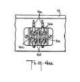
- Fig. 4a is a side view of Fig. 4, taken on the line 4a-4a in Fig. 4
- Fig. 5 is an exploded view showing in perspective how the hot plate parts are assembled
- Fig. 6 is a segment showing in elevation the MoSi2 wire after insertion in the paper slits.
- the refractory hub 1 is shown as being in the form of a cup which can be made of rigid or semi-rigid ceramic material and is formed with a circumferential series of interspaced vertical slots 2 as illustrated particularly well by Fig. 5.
- the refractory strip spokes are formed as pairs of two spokes each as shown by Fig. 5, by a single length of the strip folded to form the spokes 3 joined together by arcuate back portions 4, their radially inner ends being inserted in the slots 2 of the hub 1.
- Suitable refractory strip material is commercially available under registered trademarks FIBERFAX paper or paper board by the Carborundum Company, CERAMIC paper available from the Cortronics Company, or KAOWOOL paper or Vertel ceramic fiber woven tape and fabric, possibly rigidized by Babcox and Wilcox "3000" material which can be used up to a temperature of 3000°F (1650°C).
- the upper edges of all of the spokes, of which eight are shown, are formed with the slots 5 having V-shaped upper portions and horizontally elongated lower portions 6, these portions being interjoined by slits 7.
- the flat horizontal spiral of MoSi2 wire 8 has its portions registering with the slots pressed downwardly through the slits 7 so as to nest in the portions 6, the slits 7 pressing open to permit the passage of the wire and therefore reclosing completely or substantially so.
- the interspacing of the slots radially along the spokes 3 is made to match the pitch of the wire spiral 8 keeping in mind that the MoSi2 wire when cold is brittle and glass-like and should be free from mechanical stress both during and after insertion in the slots of the spokes.
- the MoSi2 wire is ductile at high temperatures, permitting its formation into the spiral, but it is very brittle when cold.
- the radial interspacing of the wire convolutions is kept as uniform as possible and this may require the elimination of the slots close to the axis of the spiral, leaving flat shelves 9 on which the innermost convolution rests.
- This convolution is of small diameter and does not require positive positioning in the radial direction.
- Figs. 1 and 2 show the heat element and strip assembly with the strip spokes having their bottom edges resting on a plate formed by relatively soft fibrous flat refractory discs 10 and circumferentially encircled by a soft fibrous refractory ring 11, these fibrous parts being encased by a shallow sheet metal cup 12.
- the hub or center post 1 is rigidly positioned by a tubular bolt 13 which extends through the cup bottom, the discs 10 and the bottom of the hub 1, a nut 14 being screwed on the bolt 13 and against the bottom of the cup-shaped hub 1 so as to fix the latter rigidly in position.
- the flat disc or plate rests flatly on the flat bottom wall of the cup so a firm assembly is obtained.
- the terminating ends of the MoSi2 wire spiral extend downwardly through the upper one of the discs 10 and into a pocket 15 formed in the lower one of the discs and in which the terminating ends 8a are connected via flexible wire 16 with a terminal block 17 on the outside of the wall of the sheet metal cup or casing.
- the wires 16 should be flexible enough to prevent the transmission of mechanical motion or shock from the terminal 17 to the terminating ends of the MoSi2 wire.
- the wires 16 are stranded from fine wires for maximum flexibility and are of substantial length for great flexibility, their outer ends 16a having terminals 16b screwed to flat conductor strip 16c on the terminal block. All of these parts are installed at the heater factory so that the unit as a whole can be roughly handled without damage to the MoSi2 wire.
- the terminal block has screw terminals 16d permitting installation at the stove factory.
- the hot top is installed by being provided with brackets 18 of which there are 3 although only one is shown in the drawings. These brackets are adhesively secured to the bottom of the glass plate 19 so that the hot plate is supported entirely by the glass plate.
- the brackets can be releasably connected to the hot plate by releasable screws 20, permitting removal of the hot plate for servicing. In a typical range there would be four of these hot plates, possibly of different diameters.
- the new hot plate is to be used as a small single or double heating element unit, it should still use a glass plate cover for protection of the MoSi2 wire against mechanical damage by dropped objects for example. Also, the glass plate holds down the spokes which are otherwise held in all positions excepting upside down.
- MoSi2 wire owes its ability to operate at very high temperatures to the formation of a silica or glass-like layer on its surface when exposed to oxygen at the high temperatures.
- openings 21 are formed through the side wall and the fibrous ring 11. Therefore, when the heating element is operated air is sucked in through the hollow bolt 12 and over the top edge of the cup-like hub 1 so as to flow around the wire convolution and exit through the exhause opening 21. If during initial heating of the element a slight deposit is thrown off it will be carried away by the air flow so as not to contaminate the bottom of the glass plate.
- MoSi2 wire has its lowest electrical resistivity when cold. Therefore, the instant current is applied to the heating element via the terminals 17, it immediately lights up to its incandescent state providing the 2800°F (1540°C) operating temperature producing a large amount of heat in the form of radiation. Assuming the glass plate 19 is made of the high transmittance glass a cooking utensil is heating very largely directly by radiation. Also, MoSi2 wire has a very low thermal mass and stores very little energy, so it drops quickly below incandescense when the current is discontinued.
- the strips used are relatively thin and can have a thickness only sufficient for structural stability of the wire element. They can be cut from wider material if necessary.
- the strips can be said to be made of refractory fibers as in the case of paper, or as woven from refractory threads. An optimum balance between softness and stiffness should be the objective.
- resistance wire other than MoSi2 may be developed, having the high temperature operating capability and the cold-brittle characteristics of the MoSi2 wire. If so, such wire is considered to be an equivalent of MoSi2 wire.
Landscapes
- Engineering & Computer Science (AREA)
- Chemical & Material Sciences (AREA)
- Combustion & Propulsion (AREA)
- Mechanical Engineering (AREA)
- General Engineering & Computer Science (AREA)
- Ceramic Engineering (AREA)
- Resistance Heating (AREA)
Description
- This invention relates to hot plates for cooking and particularly the type comprising a shallow sheet metal cup containing a ceramic support positioning a horizontal flat spiral of electric resistance heating wire which when supplied with current produces heat. Such hot plates are used under the bottoms of the glass plates of glass top cooking ranges.
- Hot plates particularly when installed in glass top ranges have used metal alloy electric resistance wire as a heating element (e.g. see US patent specification 3,348,025). The metal alloy wire is elastic at room temperature and is not easily damaged by rough handling of the hot plate such as occurs during shipment and installation in the range. On the other hand, it is slow to heat and cool and operates at low efficiency because the heat is transmitted to cooking utensils on the glass top largely by convection to the glass. Metal alloy resistance heating wire operates at usual temperatures between 1500°F and 2100°F (815°C and 1150°C) and has a maximum operating temperature of 2200°F (1200°C). At these temperatures the metal wire heat radiation is low. Public reaction against the low efficiency and slow heating and cooling of glass top electric ranges have resulted in some loss of their initial popularity.
- Recent development of ceramic glass with a high transmittance of infrared radiation in the range of 0.6 to 4.5 microns wavelength has not helped in solving the above indicated problem, because at the operating temperature range of metal alloy resistance wire there is only a small amount of heat radiation provided for transmittance through the high transmittance glass if it is applied as a glass top range installation.
- The high transmittance glass would have a great advantage if the heating element could be operated at the high temperatures where the heat radiation becomes substantial. For example, at 2800°F (1540°C) the wire heat radiation would become more than twice that at the 2200°F (1200°C) maximum operating temperature of metal alloy wire. The heat radiation at 2200°F (1200°C) is only 44.3% of that obtained at 2800°F (1540°C), and at the more usual metal wire operating temperature of 1500°F (850°C) the heat radiation is only 13.1% of that provided at 2800°F (1540°C).
- In the metal alloy wire is replaced by molybdenum disilicide (MoSi₂) wire the operating temperature of 2800°F (1540°C) becomes possible without requiring protection from the ambient atmosphere. The prior art, e.g. US patent 3,912,905 and 4,262,192, has made efforts to develop a hot plate using MoSi₂ wire as the heating element, because of its apparent advantages. The US patent 3,912,905 design was not commercially successful because the refractory fibers holding the wire were subject to breakage and the US patent 4,262,192 construction was unsuccessful because of the cost for fabrication and installing the wire staples supporting the heating wire.
- Unfortunately, at room temperature MoSi₂ wire is glasslike and very brittle and is easily broken by the shock of rough handling such as occurs during hot plate shipping and installation in a glass top range. This has so far also prevented commercial production of hot plates using MoSi₂ heating elements.
- The object of the present invention is to provide a hot plate using a MoSi₂ wire heating element and which solves the prior art wire breakage problem that has prevented commercialization of MoSi₂ hot plates.
- A hot plate, solving this problem is defined by the appendant claims.
- The accompanying drawings show one presently preferred form of the invention, the various figures being as follows:
Fig. 1 is a top plan view of the hot plate;
Fig. 2 is a vertical cross section taken on the line 2-2 in Fig. 1;
Fig. 3 is a segmental vertical cross section taken on the line 3-3 in Fig. 1;
Fig. 4 is a plan view showing a segment of the bottom of the hot plate and looking upwardly;
Fig. 4a is a side view of Fig. 4, taken on theline 4a-4a in Fig. 4;
Fig. 5 is an exploded view showing in perspective how the hot plate parts are assembled; and
Fig. 6 is a segment showing in elevation the MoSi₂ wire after insertion in the paper slits. - The
refractory hub 1 is shown as being in the form of a cup which can be made of rigid or semi-rigid ceramic material and is formed with a circumferential series of interspacedvertical slots 2 as illustrated particularly well by Fig. 5. The refractory strip spokes are formed as pairs of two spokes each as shown by Fig. 5, by a single length of the strip folded to form thespokes 3 joined together byarcuate back portions 4, their radially inner ends being inserted in theslots 2 of thehub 1. Suitable refractory strip material is commercially available under registered trademarks FIBERFAX paper or paper board by the Carborundum Company, CERAMIC paper available from the Cortronics Company, or KAOWOOL paper or Vertel ceramic fiber woven tape and fabric, possibly rigidized by Babcox and Wilcox "3000" material which can be used up to a temperature of 3000°F (1650°C). - The upper edges of all of the spokes, of which eight are shown, are formed with the slots 5 having V-shaped upper portions and horizontally elongated lower portions 6, these portions being interjoined by
slits 7. The flat horizontal spiral ofMoSi₂ wire 8 has its portions registering with the slots pressed downwardly through theslits 7 so as to nest in the portions 6, theslits 7 pressing open to permit the passage of the wire and therefore reclosing completely or substantially so. The interspacing of the slots radially along thespokes 3 is made to match the pitch of thewire spiral 8 keeping in mind that the MoSi₂ wire when cold is brittle and glass-like and should be free from mechanical stress both during and after insertion in the slots of the spokes. The MoSi₂ wire is ductile at high temperatures, permitting its formation into the spiral, but it is very brittle when cold. - The radial interspacing of the wire convolutions is kept as uniform as possible and this may require the elimination of the slots close to the axis of the spiral, leaving flat shelves 9 on which the innermost convolution rests. This convolution is of small diameter and does not require positive positioning in the radial direction.
- Figs. 1 and 2 show the heat element and strip assembly with the strip spokes having their bottom edges resting on a plate formed by relatively soft fibrous flat
refractory discs 10 and circumferentially encircled by a soft fibrous refractory ring 11, these fibrous parts being encased by a shallowsheet metal cup 12. The hub orcenter post 1 is rigidly positioned by atubular bolt 13 which extends through the cup bottom, thediscs 10 and the bottom of thehub 1, anut 14 being screwed on thebolt 13 and against the bottom of the cup-shaped hub 1 so as to fix the latter rigidly in position. The flat disc or plate rests flatly on the flat bottom wall of the cup so a firm assembly is obtained. - The terminating ends of the MoSi₂ wire spiral extend downwardly through the upper one of the
discs 10 and into apocket 15 formed in the lower one of the discs and in which the terminating ends 8a are connected via flexible wire 16 with aterminal block 17 on the outside of the wall of the sheet metal cup or casing. The wires 16 should be flexible enough to prevent the transmission of mechanical motion or shock from theterminal 17 to the terminating ends of the MoSi₂ wire. Preferably the wires 16 are stranded from fine wires for maximum flexibility and are of substantial length for great flexibility, their outer ends 16a having terminals 16b screwed toflat conductor strip 16c on the terminal block. All of these parts are installed at the heater factory so that the unit as a whole can be roughly handled without damage to the MoSi₂ wire. The terminal block hasscrew terminals 16d permitting installation at the stove factory. - Prior art hot plates have been installed in glass top ranges by being spring pressed against the bottom of the glass plate top. With the inherent flexibility of the glass restrained in this manner the glass tops have had a tendency to break under the impact of a carelessly placed cooking utensil.
- In the present case the hot top is installed by being provided with
brackets 18 of which there are 3 although only one is shown in the drawings. These brackets are adhesively secured to the bottom of theglass plate 19 so that the hot plate is supported entirely by the glass plate. The brackets can be releasably connected to the hot plate byreleasable screws 20, permitting removal of the hot plate for servicing. In a typical range there would be four of these hot plates, possibly of different diameters. With theglass plate 19 forming the glass top of the range and mounted as usual only by its periphery, the inherent flexibility of the glass is retained so that it is better able to absord downward shock. - If instead of a full range installation the new hot plate is to be used as a small single or double heating element unit, it should still use a glass plate cover for protection of the MoSi₂ wire against mechanical damage by dropped objects for example. Also, the glass plate holds down the spokes which are otherwise held in all positions excepting upside down.
- MoSi₂ wire owes its ability to operate at very high temperatures to the formation of a silica or glass-like layer on its surface when exposed to oxygen at the high temperatures. To assure a supply of oxygen, at various circumferentially spaced locations around the side wall of the
cup 12,openings 21 are formed through the side wall and the fibrous ring 11. Therefore, when the heating element is operated air is sucked in through thehollow bolt 12 and over the top edge of the cup-like hub 1 so as to flow around the wire convolution and exit through the exhause opening 21. If during initial heating of the element a slight deposit is thrown off it will be carried away by the air flow so as not to contaminate the bottom of the glass plate. - It can be seen that the brittle and rather fragile MoSi₂ wire spiral is positively held in position but only by the shock absorbing strip spokes, themselves protected against shock by the fibrous discs or
plates 10 and the fibrous ring 11 encircling the radially outward ends of the strips. Shocks from rough handling are not transmitted to the heating element. - MoSi₂ wire has its lowest electrical resistivity when cold. Therefore, the instant current is applied to the heating element via the
terminals 17, it immediately lights up to its incandescent state providing the 2800°F (1540°C) operating temperature producing a large amount of heat in the form of radiation. Assuming theglass plate 19 is made of the high transmittance glass a cooking utensil is heating very largely directly by radiation. Also, MoSi₂ wire has a very low thermal mass and stores very little energy, so it drops quickly below incandescense when the current is discontinued. - A glass top electric range using these new hot plates, not only provides high efficiency but a spectacular performance capability. When a hot plate is switched on incandescense is immediately obtained and when switched off the incandescense is immediately terminated.
- The strips used are relatively thin and can have a thickness only sufficient for structural stability of the wire element. They can be cut from wider material if necessary. The strips can be said to be made of refractory fibers as in the case of paper, or as woven from refractory threads. An optimum balance between softness and stiffness should be the objective.
- Possibly resistance wire other than MoSi₂ may be developed, having the high temperature operating capability and the cold-brittle characteristics of the MoSi₂ wire. If so, such wire is considered to be an equivalent of MoSi₂ wire.
Claims (5)
- An electric hot plate for use in conjunction with a high transmittance glass top comprising
a molybdenum disilicide wire (8) in the form of a flat spiral having convolutions, suitable for being attached to a source of electrical current, and supported in spaced relationship to the glass plate
characterized by
a plurality of spokes (3) extending radially outwardly from a central hub (2) in a horizontal plane, the spokes being formed by refractory fibrous or woven flat strips each positioned in a vertical plane and having upper edges in which downwardly extending slots having upper portions and enlarged lower portions (6) interjoined by slits (7) are formed, wherein the lower portions (6) are adapted to physically retain a portion of the wire (8) inserted into the slot (5), the flat strips being stiff enough for resisting its displacement, while allowing movement of the wire (8) due to thermal expansion and displacement due to to mechanical shock imparted on the hot plate, but soft enough to absorb the transmission of mechanical shock imparted on the hot plate so as to resist breakage of the wire (8). - The hot plate of claim 1
characterized in that
the spokes are soft enough so as to elastically deform as the wire (8) is being pushed through the slit portion (7) of the slot (5) to the lower portion and then resume its original configuration after the installation of the wire (8) into the lower portion (6) for physically retaining the wire. - The hot plate according to claims 1 or 2
characterized in that
each two of said spokes is formed by a single length of said strip having outer ends joined together circumferentially by an arcuate section of the strip. - The hot plate according to claim 1 or 2 or 3
characterized by
a central refractory hub (1), a shallow cup (12), a flat refractory disc (10) within said cup (12) for supporting the spokes (3) and for urging the spokes (3) against the high transmittance glass top (19), and a central bolt (13) passing through the hub (1), disc (10) and cup (12). - The hot plate according to claim 4
characterized in that
the central bolt (13) includes a hollow axial portion, and the cup (12) includes portions (21) for allowing the passage of gas, especially heated air.
Applications Claiming Priority (2)
| Application Number | Priority Date | Filing Date | Title |
|---|---|---|---|
| US06/720,733 US4894515A (en) | 1985-04-08 | 1985-04-08 | Hot plate for cooking |
| US720733 | 1985-04-08 |
Publications (3)
| Publication Number | Publication Date |
|---|---|
| EP0197547A2 EP0197547A2 (en) | 1986-10-15 |
| EP0197547A3 EP0197547A3 (en) | 1988-08-17 |
| EP0197547B1 true EP0197547B1 (en) | 1991-07-17 |
Family
ID=24895086
Family Applications (1)
| Application Number | Title | Priority Date | Filing Date |
|---|---|---|---|
| EP86104796A Expired - Lifetime EP0197547B1 (en) | 1985-04-08 | 1986-04-08 | Hot plate for cooking |
Country Status (3)
| Country | Link |
|---|---|
| US (1) | US4894515A (en) |
| EP (1) | EP0197547B1 (en) |
| DE (1) | DE3680224D1 (en) |
Families Citing this family (7)
| Publication number | Priority date | Publication date | Assignee | Title |
|---|---|---|---|---|
| DE3812490A1 (en) * | 1988-04-15 | 1989-11-02 | Ego Elektro Blanc & Fischer | BEAM RADIATOR |
| DE3935031A1 (en) * | 1989-10-20 | 1991-04-25 | Wacker Chemie Gmbh | radiant heater |
| US5324920A (en) * | 1990-10-18 | 1994-06-28 | Tokyo Electron Sagami Limited | Heat treatment apparatus |
| EP0624997A3 (en) * | 1993-05-12 | 1995-01-11 | Belzig Elektrowaerme Gmbh | Radiant electric heaters for glass-ceramic cooking plates. |
| SE513409C2 (en) * | 1997-07-01 | 2000-09-11 | Kanthal Ab | IR source consisting of a high temperature helical element, which is placed in an open reflector |
| DE102005042799A1 (en) | 2005-09-08 | 2007-03-22 | BSH Bosch und Siemens Hausgeräte GmbH | Universal holder for hobs |
| US10251217B2 (en) * | 2013-06-14 | 2019-04-02 | Sandvik Kk | Molybdenum disilicide-based ceramic heating element holding structure |
Citations (1)
| Publication number | Priority date | Publication date | Assignee | Title |
|---|---|---|---|---|
| US4262192A (en) * | 1979-08-15 | 1981-04-14 | The Kanthal Corporation | Molybdenum disilicide resistance wire and support |
Family Cites Families (8)
| Publication number | Priority date | Publication date | Assignee | Title |
|---|---|---|---|---|
| US3346721A (en) * | 1965-02-01 | 1967-10-10 | Gen Motors Corp | Radiant heater with improved seal assembly |
| US3346720A (en) * | 1965-05-25 | 1967-10-10 | Gen Motors Corp | Infrared surface heating unit with corrugated ribbon-shaped filament |
| US3348025A (en) * | 1965-06-24 | 1967-10-17 | Gen Motors Corp | Spider supported electric heater |
| NL7100788A (en) * | 1971-01-21 | 1972-07-25 | ||
| DE2165569C3 (en) * | 1971-12-30 | 1986-05-28 | E.G.O. Elektro-Geräte Blanc u. Fischer, 7519 Oberderdingen | Electric cooker with a top plate made of highly heat-resistant glass-like or ceramic material |
| US3912905A (en) * | 1974-02-25 | 1975-10-14 | Kanthal Corp | Electric resistance heating device |
| US4221672A (en) * | 1978-02-13 | 1980-09-09 | Micropore International Limited | Thermal insulation containing silica aerogel and alumina |
| US4508961A (en) * | 1982-03-02 | 1985-04-02 | Micropore International Limited | Electric radiant heater units for glass ceramic top cookers |
-
1985
- 1985-04-08 US US06/720,733 patent/US4894515A/en not_active Expired - Fee Related
-
1986
- 1986-04-08 EP EP86104796A patent/EP0197547B1/en not_active Expired - Lifetime
- 1986-04-08 DE DE8686104796T patent/DE3680224D1/en not_active Expired - Lifetime
Patent Citations (1)
| Publication number | Priority date | Publication date | Assignee | Title |
|---|---|---|---|---|
| US4262192A (en) * | 1979-08-15 | 1981-04-14 | The Kanthal Corporation | Molybdenum disilicide resistance wire and support |
Also Published As
| Publication number | Publication date |
|---|---|
| EP0197547A2 (en) | 1986-10-15 |
| EP0197547A3 (en) | 1988-08-17 |
| DE3680224D1 (en) | 1991-08-22 |
| US4894515A (en) | 1990-01-16 |
Similar Documents
| Publication | Publication Date | Title |
|---|---|---|
| CA1066343A (en) | Flat plate heating unit with foil heating means | |
| US3987275A (en) | Glass plate surface heating unit with sheathed heater | |
| US5571434A (en) | Cooktop stamping having means for attaching heating elements and an integral trim ring | |
| EP0149267B1 (en) | Heating apparatus | |
| US4845340A (en) | Electric radiant heating element for heating a plate particularly a glass ceramic plate | |
| GB2213690A (en) | A temperature sensor assembly for an automatic surface unit | |
| US3733462A (en) | Heating element for flush top ranges | |
| US3346720A (en) | Infrared surface heating unit with corrugated ribbon-shaped filament | |
| US4894515A (en) | Hot plate for cooking | |
| JPS63500061A (en) | Improvement of infrared heater | |
| JPH04503887A (en) | Heating equipment for heat treating food, especially cooking hot plates | |
| US4357523A (en) | Electrical heating means for cookers or hot plates | |
| JPH06101850A (en) | Electric heating device for range for cooking | |
| US6067404A (en) | Radiant electric heater with fabric covering sheet | |
| US6120282A (en) | Glass-ceramic plate and its manufacturing process | |
| JPS6010579A (en) | Heater | |
| NO893018L (en) | HEATING PLATE / HEATING UNIT FOR COOKING. | |
| EP0174774A1 (en) | Heating apparatus | |
| GB2154405A (en) | Heating apparatus | |
| CA1228390A (en) | Heating apparatus | |
| US5994674A (en) | Hob | |
| JPH0372892B2 (en) | ||
| EP0162620A2 (en) | A cooking arrangement | |
| GB2277145A (en) | A hob | |
| EP0169643B1 (en) | Heating apparatus |
Legal Events
| Date | Code | Title | Description |
|---|---|---|---|
| PUAI | Public reference made under article 153(3) epc to a published international application that has entered the european phase |
Free format text: ORIGINAL CODE: 0009012 |
|
| AK | Designated contracting states |
Kind code of ref document: A2 Designated state(s): DE FR GB IT SE |
|
| PUAL | Search report despatched |
Free format text: ORIGINAL CODE: 0009013 |
|
| AK | Designated contracting states |
Kind code of ref document: A3 Designated state(s): DE FR GB IT SE |
|
| 17P | Request for examination filed |
Effective date: 19890125 |
|
| 17Q | First examination report despatched |
Effective date: 19890904 |
|
| GRAA | (expected) grant |
Free format text: ORIGINAL CODE: 0009210 |
|
| AK | Designated contracting states |
Kind code of ref document: B1 Designated state(s): DE FR GB IT SE |
|
| REF | Corresponds to: |
Ref document number: 3680224 Country of ref document: DE Date of ref document: 19910822 |
|
| ITF | It: translation for a ep patent filed | ||
| ET | Fr: translation filed | ||
| PGFP | Annual fee paid to national office [announced via postgrant information from national office to epo] |
Ref country code: GB Payment date: 19920406 Year of fee payment: 7 |
|
| PGFP | Annual fee paid to national office [announced via postgrant information from national office to epo] |
Ref country code: SE Payment date: 19920416 Year of fee payment: 7 |
|
| PGFP | Annual fee paid to national office [announced via postgrant information from national office to epo] |
Ref country code: FR Payment date: 19920424 Year of fee payment: 7 |
|
| PGFP | Annual fee paid to national office [announced via postgrant information from national office to epo] |
Ref country code: DE Payment date: 19920514 Year of fee payment: 7 |
|
| PLBE | No opposition filed within time limit |
Free format text: ORIGINAL CODE: 0009261 |
|
| STAA | Information on the status of an ep patent application or granted ep patent |
Free format text: STATUS: NO OPPOSITION FILED WITHIN TIME LIMIT |
|
| 26N | No opposition filed | ||
| PG25 | Lapsed in a contracting state [announced via postgrant information from national office to epo] |
Ref country code: GB Effective date: 19930408 |
|
| PG25 | Lapsed in a contracting state [announced via postgrant information from national office to epo] |
Ref country code: SE Effective date: 19930409 |
|
| GBPC | Gb: european patent ceased through non-payment of renewal fee |
Effective date: 19930408 |
|
| PG25 | Lapsed in a contracting state [announced via postgrant information from national office to epo] |
Ref country code: FR Effective date: 19931229 |
|
| PG25 | Lapsed in a contracting state [announced via postgrant information from national office to epo] |
Ref country code: DE Effective date: 19940101 |
|
| REG | Reference to a national code |
Ref country code: FR Ref legal event code: ST |
|
| EUG | Se: european patent has lapsed |
Ref document number: 86104796.7 Effective date: 19931110 |
|
| PG25 | Lapsed in a contracting state [announced via postgrant information from national office to epo] |
Ref country code: IT Free format text: LAPSE BECAUSE OF NON-PAYMENT OF DUE FEES;WARNING: LAPSES OF ITALIAN PATENTS WITH EFFECTIVE DATE BEFORE 2007 MAY HAVE OCCURRED AT ANY TIME BEFORE 2007. THE CORRECT EFFECTIVE DATE MAY BE DIFFERENT FROM THE ONE RECORDED. Effective date: 20050408 |