EP0196822B1 - Air-in-line detector - Google Patents
Air-in-line detector Download PDFInfo
- Publication number
- EP0196822B1 EP0196822B1 EP86302005A EP86302005A EP0196822B1 EP 0196822 B1 EP0196822 B1 EP 0196822B1 EP 86302005 A EP86302005 A EP 86302005A EP 86302005 A EP86302005 A EP 86302005A EP 0196822 B1 EP0196822 B1 EP 0196822B1
- Authority
- EP
- European Patent Office
- Prior art keywords
- light
- fluid
- detector
- air
- line
- Prior art date
- Legal status (The legal status is an assumption and is not a legal conclusion. Google has not performed a legal analysis and makes no representation as to the accuracy of the status listed.)
- Expired - Lifetime
Links
Images

Classifications
-
- A—HUMAN NECESSITIES
- A61—MEDICAL OR VETERINARY SCIENCE; HYGIENE
- A61M—DEVICES FOR INTRODUCING MEDIA INTO, OR ONTO, THE BODY; DEVICES FOR TRANSDUCING BODY MEDIA OR FOR TAKING MEDIA FROM THE BODY; DEVICES FOR PRODUCING OR ENDING SLEEP OR STUPOR
- A61M5/00—Devices for bringing media into the body in a subcutaneous, intra-vascular or intramuscular way; Accessories therefor, e.g. filling or cleaning devices, arm-rests
- A61M5/36—Devices for bringing media into the body in a subcutaneous, intra-vascular or intramuscular way; Accessories therefor, e.g. filling or cleaning devices, arm-rests with means for eliminating or preventing injection or infusion of air into body
- A61M5/365—Air detectors
-
- A—HUMAN NECESSITIES
- A61—MEDICAL OR VETERINARY SCIENCE; HYGIENE
- A61M—DEVICES FOR INTRODUCING MEDIA INTO, OR ONTO, THE BODY; DEVICES FOR TRANSDUCING BODY MEDIA OR FOR TAKING MEDIA FROM THE BODY; DEVICES FOR PRODUCING OR ENDING SLEEP OR STUPOR
- A61M2205/00—General characteristics of the apparatus
- A61M2205/12—General characteristics of the apparatus with interchangeable cassettes forming partially or totally the fluid circuit
-
- A—HUMAN NECESSITIES
- A61—MEDICAL OR VETERINARY SCIENCE; HYGIENE
- A61M—DEVICES FOR INTRODUCING MEDIA INTO, OR ONTO, THE BODY; DEVICES FOR TRANSDUCING BODY MEDIA OR FOR TAKING MEDIA FROM THE BODY; DEVICES FOR PRODUCING OR ENDING SLEEP OR STUPOR
- A61M5/00—Devices for bringing media into the body in a subcutaneous, intra-vascular or intramuscular way; Accessories therefor, e.g. filling or cleaning devices, arm-rests
- A61M5/14—Infusion devices, e.g. infusing by gravity; Blood infusion; Accessories therefor
-
- Y—GENERAL TAGGING OF NEW TECHNOLOGICAL DEVELOPMENTS; GENERAL TAGGING OF CROSS-SECTIONAL TECHNOLOGIES SPANNING OVER SEVERAL SECTIONS OF THE IPC; TECHNICAL SUBJECTS COVERED BY FORMER USPC CROSS-REFERENCE ART COLLECTIONS [XRACs] AND DIGESTS
- Y10—TECHNICAL SUBJECTS COVERED BY FORMER USPC
- Y10S—TECHNICAL SUBJECTS COVERED BY FORMER USPC CROSS-REFERENCE ART COLLECTIONS [XRACs] AND DIGESTS
- Y10S128/00—Surgery
- Y10S128/13—Infusion monitoring
Definitions
- This invention relates generally to air-in-line detectors.
- the present invention relates to an air-in-line detector which uses a series of optical sensors spaced axially along a fluid flow line and having selectively different light sensitivities and selectively different optical path arrangements to provide a sequence of signals for determining whether an air bubble is present in the fluid flow line. More specifically, the present invention relates to an air-in-line detector which is insensitive to changes in the level of ambient light and which can determine the presence of air bubbles in a fluid line regardless of the opacity or opalescence of the fluid. This invention is particularly, but not exclusively, suited for use with an I.V. infusion pump or controller to determine the presence of air bubbles in the I.V. administration fluid flow line.
- U.S. Patent No. 3,898,637 suggests using an electrical conductivity indicator to determine whether there is an air-in-line condition.
- U.S. Patent No. 2,573,390 suggests using a detector for compression wave propagation for this purpose.
- U.S. Patent No. 3,974,683 discloses use of an ultrasonic detector, and
- U.S. Patent No. 4,384,578 suggests the use of a temperature differential indicator to determine the presence of air in a fluid line.
- various arrangements have been proposed which use optical sensors to detect the presence of air in a fluid line.
- optical sensors will provide signals which can be interpreted by logic circuitry to indicate certain flow conditions.
- An example of such an arrangement is disclosed in U.S. Patent No. 4,366,384.
- U.S. Patent No. 4,114,144 which is assigned to the assignee of the present application discloses a device for detecting air-in-line conditions using optical sensors.
- These references both rely on the refractive properties of fluids and the ability of an opaque fluid to occlude a light path. For instance, it is well known that an optical sensor which comprises a light emitter that directs light diametrically through clear tubing to a light detector will discriminate between conditions which block the path of light and those that do not.
- Such a sensor can distinguish between an opaque fluid in the line which blocks the light beam and air in the line which allows light from the emitter to pass to the detector.
- This direct path arrangement would not differentiate between a clear fluid and air unless the detector is somehow sensitized to detect increased light intensity caused by the focus effect of clear fluid in the line.
- the focus effect becomes increasingly negligible with an increase in opalescence or opacity of the fluid. In fact, increased fluid opacity will eventually make the sensor ineffectual to distinguish between air and fluid in the tubing.
- an optical sensor can be structured to work with a refracted or indirect light path.
- the light from a light emitter is directed substantially tangential to the fluid column and a light detector, located diametrically opposite the emitter on the other side of the tube, will complete the optical path between emitter and detector only when a clear fluid is in the tube to refract the light beam.
- This refracted path arrangement unlike the direct path arrangement discussed previously, is capable of differentiating between clear fluid and air in the tubing.
- the refracted path arrangement does not differentiate between air and an opaque fluid since in either case light does not reach the detector. Further, like the direct path arrangement, the refracted path arrangement becomes unreliable at the point where a translucent or opalescent material is in the line and light is blocked rather than refracted.
- the present invention recognizes that there is a need for an air-in-line detector which can make the general distinction between air and fluid regardless of the opacity of the fluid. Additionally, the present invention recognizes that where optical sensors are used in an air-in-line detector, changes in the level of ambient light may activate or deactive a light detector to give a false indication of the actual condition.
- the present invention has addressed the problems of changing ambient light levels and opalescent fluid in line and has determined that the broad distinction between fluid and air in an I.V. line can be made, under any light condition and regardless of the opacity of the fluid, by selectively arranging optical sensors in series according to their sensitivity to light and according to their dependence on direct or refracted light for activation. Further, the present invention contemplates that a microprocessor logic program will provide information for an accurate indication of air-in-line in accordance with the sequencing of changes in the ON-OFF state of various individidual sensors.
- An object of the present invention is to provide a reliable air-in-line detector for an I.V. fluid line which provides an accurate indication of air-in-line regardless of the opacity or opalescence of the fluid being administered through the fluid line.
- Another object of the present invention is to provide an air-in-line detector which is insensitive to ambient light levels and will therefore continue to provide accurate indications of the absence or presence of air in the fluid line despite changes in the ambient light level. It is yet another object of the present invention to provide an air-in-line detector that is relatively inexpensivfe and easy to manufacture and which is simple to operate.
- a detector for automatically determining the presence of air in a fluid line comprising:
- a detector comprises a first ON-OFF optical sensor having a light emitter and a light detector which are operatively associated with an I.V. fluid line to produce ON-OFF signals according to whether light can travel a direct line optical path between the detector and the sensor.
- An ON signal is indicated when either air or a clear fluid is present in the fluid line.
- the detector of the present invention also includes a second ON-OFF optical sensor having a light emitter and a light detector which are operatively associated with the I.V. tube downstream from the first optical sensor.
- the second optical sensor has a relatively lower light threshold than the first optical sensor, and it produces ON-OFF signals according to whether light can travel a refracted optical path from its emitter to its detector.
- the automatic air-in-line detector of the present invention also includes a microprocessed logic circuitry which is operatively connected with the first and second optical sensors to alarm and stop operation of the fluid infusion apparatus in accordance with pre-programmed sequencing of ON-OFF signals from the first and second optical sensors.
- a plurality of optical sensors can be arranged axially along the fluid path in accordance with the present invention to provide for redundancy in the system.
- Pump 10 may include an automatic air-in-line fluid detector having a support portion 12 for receiving a fluid line 22.
- pump 10 is mounted on a pole 14 and a bottle of fluid 16 to be infused is supported above the pump 10. Fluid from the bottle 16 is allowed to flow downward through a fluid line 18 and enter a disposable cassette 20.
- pump 10 provides for an accurate pumping of the fluid from the cassette 20 to an outside fluid line 22.
- the pump 10 may include a pair of dials, such as dials 24 and 26, which control the rate of fluid flow to the fluid line 22 and the volume of fluid which is to flow through the line 22 to the patient.
- means 28 for allowing infusion of the fluid to the patient.
- means 28 may include a hypodermic needle which is used to infuse fluid into the vein of the patient.
- the pump 10 may be of the type disclosed in U.S. Patent No. 3,985,133, which is assigned to the same assignee as the instant application. It is to be appreciated, however, that the automatic air-in-line fluid detector of the present invention may be used with other types of fluid pumps. Further, the automatic air-in-line detector of the present invention may be used with any type of gravity feed means for infusing fluid to a patient, such as controller.
- the fluid line 22 passing from the cassette 20 is positioned within a channel 56 in the support portion 12.
- the support 12 includes a plurality of detector elements which in combination with appropriate electronic circuitry provide for an automatic detection of air-in-line.
- FIGS 2 through 7 show the details of the construction of the support 12.
- support 12 includes a base 50 having an open front with a pair of tapered sides 52 and 54 leading to circular channel 56 which channel receives the fluid line 22 in position for detection of the contents passing through line 22.
- a plurality of light emitters and light detectors are disposed along the channel 56 on opposite sides of the chaannel to provide for the detection of air-in-line regardless of the opacity of the fluid normally in the line 22.
- a plurality of light emitters 30, 32, 34, 36 and 38 are respectively positioned in a plurality of emitter openings 58, 60, 62, 64 and 66 in base 50 which optically communicate with one side of the channel 56.
- Base 50 is also provided with a recess portion 68 to provide access to the openings 58, 60, 62, 64 and 66 to properly position the light emitters 30, 32, 34, 36 and 38 and to provide for the necessary electrical wiring (not shown) to the light emitters.
- Light emitters of a type well known in the art, such as Model No. SE-5455-3 manufactured by Spectronics, can be used for the present invention.
- these light emitters may be light emitting diodes which provide for a light output spectrum in the infrared range. Although either visible or invisible light can be used, since certain drugs are light sensitive, the infrared light spectrum may be preferred in order to provide for a proper detection without damaging the drug solutions.
- a plurality of light detectors 40, 42, 44, 46 and 48 such as phototransistors having a light detection spectrum complementary to the light emitters are respectively positioned in a plurality of detector openings 70, 72, 74, 76 and 78 which optically communicate between a recessed area 80 in base 50 and the channel 56.
- Light detectors or photo transistors of a type well known in the art, such as Model No. SPX-2532 manufactured by Spectronics, will serve the purposes of the present invention.
- the detectors 42 and 44 positioned respectively in openings 72 and 74, are more sensitive to light than are the detectors 40, 46 and 48.
- detectors 42 and 44 will change from an OFF condition (absence of light) to an ON condition (detection of light), and vice versa, at a lower threshold of light intensity, or higher degree of fluid opacity, than required to change the ON-OFF condition of detectors 40, 46 and 48.
- the same result can be accomplished by effectively increasing the intensity of emitters 32 and 34 relative to emitters 30, 36 and 38. If this is done, the sensitivity of detectors 40, 42, 44, 46 and 48 may all be the same or varied as discussed above. There are several ways, all well known in the pertinent art, by which detector sensitivity and emitter intensity can be varied to accomplish the purposes of the present invention.
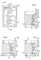
- the emitters 30, 36 and 38 and respective detectors 40, 46 and 48 are aligned along the same axis for providing a direct optical path substantially along the diameter of a cross-sectional area of the fluid line 22, such as shown for emitter 30 and detector 40 in Figure 7.
- a transparent fluid or air is present in the portion of fluid line 22 positioned in the channel 56, light energy freely passes from an emitter to its complementary detector arranged as shown in Figure 7.
- the emitters and detectors positioned in openings 64, 66, 76 and 78 are arranged along the same axis in the same way as that shown in Figure 7.
- emitters 32 and 34 and detectors 42 and 44 are offset from each other. Specifically, with reference to Figure 5, emitter 34 in opening 62 is arranged to direct light energy through the channel 56 but at a rearward position of the channel 56. In addition, the detector 44 is set at an angle. When there is a transparent fluid in the line 22, the light from emitter 34 is refracted by the fluid to pass to detector 44. However, if air is in tube 22, the light from emitter 34 is not refracted and it does not pass to the detector 44.
- the operation of the emitter 32 and detector 42 in the openings 60 and 72 shown in Figure 6 are essentially similar to that shown in Figure 5 and described above except they are located to the front of the channel 56. The positioning of these emitters and detectors ensures detection on both sides of the fluid line 22 and enables the detector to detect larger air bubbles but allow small air bubbles which are not harmful to pass.
- first optical sensor 90 is positioned upstream from second optical sensor 92. Accordingly, the leading edge of an air bolus in the fluid line 22 will pass first optical sensor 90 before passing second optical sensor 92.
- first optical sensor 90 is adjusted to a higher light intensity than is detector 42 of second optical sensor 92.
- first optical sensor 90 will change to an OFF condition (no detection of light) before optical sensor 92.
- first optical sensor 90 be arranged in a manner as shown in Figure 7 for a direct light path diametrically through the lumen of the I.V. tube 22. This direct path arrangement minimizes or eliminates any refraction of the light path by fluid in the line.
- second optical sensor 92 be arranged as shown in Figure 5 or Figure 6 so that the passage of light from emitter 32 to detector 42 is dependent upon a refracted light beam.
- second optical sensor 92 will not pass light when there is either air in fluid line 22, since air does not effectively refract light, or when there is a sufficiently opaque fluid in the line 22 which will not effectively pass the light ray.
- microprocessor (not shown) to accomplish the purposes of the present invention can be best understood by reference to Logic tables. It is understood that various microprocessor programs can be generated by the skilled artisan to accomplish the purposes of the present invention in accordance with the disclosed logic. Although several microprocessors are available, for the purposes of the preferred embodiment, microprocessors of the type 8051 manufactured by Intel Corporation and identified by MCS Series are preferred.
- Table I assumes an initial condition wherein a clear fluid is passing through the fluid line 22 in a direction indicated by the arrow 88 in Figures 8a, b, c and d. Under this condition, both first sensor 90 and second sensor 92 are in the ON condition indicating that light from the emitter of each optical sensor is being sensed by the detector of each sensor. Also shown in Table I is the effect of an increase in the opalescence or opacity of the fluid passing through the I.V. line 22. Under this situation, sensor 90 will change to the OFF condition before sensor 92 because sensor 92 requires less light intensity for the ON condition than does sensor 90. In this situation there should be no alarm.
- a logic program could be established in a microprocessor by a skilled artisan whereby an alarm is activated whenever sensors 90 and 92 are initially in an ON condition and then sensor 92 turns to an OFF condition.
- Logic circuitry can be established to ignore changes in sensor 90 from ON to OFF which would only indicate either increased opacity in fluid line 22 or decrease in ambient light. Indeed, even if operation is such that sensor 90 is OFF and sensor 92 is ON, the passage of an air bubble will first change sensor 90 to an ON condition before affecting sensor 92. Thus, for at least an instant, there will be a return to the initial ON-ON condition. In this manner, when an initially clear fluid is in the line, it can be seen that the apparatus is rendered insensitive to the opalescence of a fluid passing through the LV. tube and to a decrease in the ambient liqht level.
- Table 11 is arranged to show a situation wherein the inline fluid is initially opaque.
- a decrease in the opalescence or opacity of the fluid causes the second sensor, sensor 92, to turn ON before first sensor 90 because it requires less light to be activated.
- an effective increase in ambient light level may also cause sensor 92 to turn ON for the same reason.
- a decrease in the ambient light has no effect on sensors 90 and 92 since they are already in the OFF condition. In any of these situations, there is a safe operation and no alarm should be indicated.
- the sensor 90 changes to an ON condition because the air bolus or bubble allows for the passage of light on the direct optical path between emitter 30 and detector 40. As air passes sensor 92, it will remain OFF because the air will not refract the light from emitter 32 so as to be received by optical detector 42. Again, as in the situation with an initially clear fluid, air in the line causes sensor 90 to be ON and sensor 92 OFF. An alarm condition is indicated.
- Table III indicates the situation in which an opalescent or translucent fluid is initially present in the fluid line 22.
- the relative conditions of sensor 90 and 92 may be ON-ON, OFF-OFF or OFF-ON depending upon whether the fluid is relatively clear, relatively opaque or somewhere in between. Regardless, the same logic discussed above applies here in getting sensor 90 to the ON condition and sensor 92 to the OFF condition to alarm the system.
- Redundancy can be built into the system by selectively providing additional sensors arranged in a sequence to provide for the creation of signals in accordance with the logic discussed above. More specifically, in the preferred embodiment, a plurality of light emitters and their respective light detectors arranged as shown in Figures 8a, b, c and d comprise a series of optical sensors. Further, it can be appreciated that detectors 40, 46 and 48 are arranged to respectively receive direct light diametrically across the lumen of tube 22 from emitters 30,36 and 38. Also it should be appreciated that detectors 42 and 44 are positioned to receive refracted light from emitters 32 and 34 which are positioned to beam light at the periphery of the fluid flow path as fluid flows through the tube 22.
- detector 44 is selected to have higher light sensitivity. Accordingly, under the same lighting conditions detector 44 will detect light at lower intensity levels than detector 46. This, of course, permits a similar insensitivity for either fluid opacity or changes in ambient light levels to the insensitivities previously discussed for sensors 90 and 92.
- the logic circuitry always considers the ON-OFF conditions of any two adjacent detectors.
- standard I.V. tubes which have relatively small inner diameters, it has been determined that air bubbles that affect only one optical sensor at a time pose negligible risk to the patient.
- the spacing of the optical sensors along the fluid line 22 can be adjusted to detect larger or smaller air bubbles according to the desires of the operator.
Description
- This invention relates generally to air-in-line detectors.
- Specifically, the present invention relates to an air-in-line detector which uses a series of optical sensors spaced axially along a fluid flow line and having selectively different light sensitivities and selectively different optical path arrangements to provide a sequence of signals for determining whether an air bubble is present in the fluid flow line. More specifically, the present invention relates to an air-in-line detector which is insensitive to changes in the level of ambient light and which can determine the presence of air bubbles in a fluid line regardless of the opacity or opalescence of the fluid. This invention is particularly, but not exclusively, suited for use with an I.V. infusion pump or controller to determine the presence of air bubbles in the I.V. administration fluid flow line.
- During the infusin of LV. fluids to a patient, it is important that the fluid flow line be monitored to insure that a minimum amount of air is infused with the fluid. Although a small amount of air may inadvertently be infused to the patient without adverse effects, the infusion of relatively larger amounts of air can be extremely dangerous. Thus, as has been previously recognized, it is important to provide a means to determine whether air is present in the I.V. fluid flow line.
- Various apparatus and methods have been suggested to solve the air-in-line problem. For example, U.S. Patent No. 3,898,637 suggests using an electrical conductivity indicator to determine whether there is an air-in-line condition. U.S. Patent No. 2,573,390 suggests using a detector for compression wave propagation for this purpose. Further, U.S. Patent No. 3,974,683 discloses use of an ultrasonic detector, and U.S. Patent No. 4,384,578 suggests the use of a temperature differential indicator to determine the presence of air in a fluid line. Additionally, like the present invention, various arrangements have been proposed which use optical sensors to detect the presence of air in a fluid line.
- Four separate states or conditions of flow through the LV. tubing can be identified during the administration of I.V. fluid to a patient. Briefly, these conditions are: (c) fluid in line which is somewhere between being clear or opaque such as an opalescent or translucent fluid, and (d) air in line. Of course, the object of an accurate and reliable air-in-line detector is to distinguish any of the first three conditions from the air-in-line condition.
- If a clear plastic I.V. administration tubing set is used, optical sensors will provide signals which can be interpreted by logic circuitry to indicate certain flow conditions. An example of such an arrangement is disclosed in U.S. Patent No. 4,366,384. Also U.S. Patent No. 4,114,144 which is assigned to the assignee of the present application discloses a device for detecting air-in-line conditions using optical sensors. These references both rely on the refractive properties of fluids and the ability of an opaque fluid to occlude a light path. For instance, it is well known that an optical sensor which comprises a light emitter that directs light diametrically through clear tubing to a light detector will discriminate between conditions which block the path of light and those that do not. Thus, such a sensor can distinguish between an opaque fluid in the line which blocks the light beam and air in the line which allows light from the emitter to pass to the detector. This direct path arrangement, however, would not differentiate between a clear fluid and air unless the detector is somehow sensitized to detect increased light intensity caused by the focus effect of clear fluid in the line. The focus effect, however, becomes increasingly negligible with an increase in opalescence or opacity of the fluid. In fact, increased fluid opacity will eventually make the sensor ineffectual to distinguish between air and fluid in the tubing.
- The earlier references have also found that an optical sensor can be structured to work with a refracted or indirect light path. In such a sensor the light from a light emitter is directed substantially tangential to the fluid column and a light detector, located diametrically opposite the emitter on the other side of the tube, will complete the optical path between emitter and detector only when a clear fluid is in the tube to refract the light beam. This refracted path arrangement, unlike the direct path arrangement discussed previously, is capable of differentiating between clear fluid and air in the tubing. The refracted path arrangement, however, does not differentiate between air and an opaque fluid since in either case light does not reach the detector. Further, like the direct path arrangement, the refracted path arrangement becomes unreliable at the point where a translucent or opalescent material is in the line and light is blocked rather than refracted.
- The present invention recognizes that there is a need for an air-in-line detector which can make the general distinction between air and fluid regardless of the opacity of the fluid. Additionally, the present invention recognizes that where optical sensors are used in an air-in-line detector, changes in the level of ambient light may activate or deactive a light detector to give a false indication of the actual condition.
- Accordingly, the present invention has addressed the problems of changing ambient light levels and opalescent fluid in line and has determined that the broad distinction between fluid and air in an I.V. line can be made, under any light condition and regardless of the opacity of the fluid, by selectively arranging optical sensors in series according to their sensitivity to light and according to their dependence on direct or refracted light for activation. Further, the present invention contemplates that a microprocessor logic program will provide information for an accurate indication of air-in-line in accordance with the sequencing of changes in the ON-OFF state of various individidual sensors.
- An object of the present invention is to provide a reliable air-in-line detector for an I.V. fluid line which provides an accurate indication of air-in-line regardless of the opacity or opalescence of the fluid being administered through the fluid line. Another object of the present invention is to provide an air-in-line detector which is insensitive to ambient light levels and will therefore continue to provide accurate indications of the absence or presence of air in the fluid line despite changes in the ambient light level. It is yet another object of the present invention to provide an air-in-line detector that is relatively inexpensivfe and easy to manufacture and which is simple to operate.
- According to one aspect of the present invention we provide a detector for automatically determining the presence of air in a fluid line comprising:
- means for supporting a portion of the fluid line in a position to be detected;
- a first light-sensitive ON-OFF means operatively associated with the fluid line to generate an ON signal when air or a relatively transparent fluid is in the fluid line;
- a second light-sensitive ON-OFF means requiring less light intensity for its ON condition than said first ON-OFF means and being operatively associated with the fluid line to generate an OFF signal when air or a relatively opaque fluid is in the fluid line; and
- means operatively coupled to said first and second means to alarm when simultaneously said first means indicates ON and said second means indicates OFF.
- In one arrangement according to the invention there is provided a third light-sensitive ON-OFF means operatively associated with the fluid line, downstream from said second means, for producing an ON signal when air or a relatively transparent fluid is in the fluid line and the means operatively coupled to said first and second means are coupled to the third ON-OFF means to alarm whenever said second means indicates OFF simultaneously when either said first or said third means indicates ON.
- In a further arrangement according to the invention there is provided a third light-sensitive ON-OFF means adjacent said second ON-OFF means and axially opposite said first ON-OFF means and operatively associated with the fluid line to generate an OFF signal when air or a relatively opaque fluid is in the fluid line;
- a fourth light-sensitive ON-OFF means adjacent said third ON-OFF means and axially opposite said second ON-OFF means and operatively associated with the fluid line to generate an ON signal when air or a relatively clear fluid is in the fluid line; and
- means operatively coupled to said third and fourth ON-OFF means to alarm and indicate air in the fluid line when simultaneously said third means indicates OFF and said fourth means indicates ON.
- In a particular preferred embodiment according to the invention a detector comprises a first ON-OFF optical sensor having a light emitter and a light detector which are operatively associated with an I.V. fluid line to produce ON-OFF signals according to whether light can travel a direct line optical path between the detector and the sensor. An ON signal is indicated when either air or a clear fluid is present in the fluid line. The detector of the present invention also includes a second ON-OFF optical sensor having a light emitter and a light detector which are operatively associated with the I.V. tube downstream from the first optical sensor. The second optical sensor has a relatively lower light threshold than the first optical sensor, and it produces ON-OFF signals according to whether light can travel a refracted optical path from its emitter to its detector. An ON signal is indicated for the second sensor when a relatively clear fluid is in the line which will refract light from the emitter and direct it to the detector. Accordingly, an OFF signal is indicated when light from the emitter is not refracted toward the detector, as when air is in the line, or a relatively opaque fluid is in the fluid line to block the light from reaching the detector. The automatic air-in-line detector of the present invention also includes a microprocessed logic circuitry which is operatively connected with the first and second optical sensors to alarm and stop operation of the fluid infusion apparatus in accordance with pre-programmed sequencing of ON-OFF signals from the first and second optical sensors. As will be appreciated by the skilled artisan, a plurality of optical sensors can be arranged axially along the fluid path in accordance with the present invention to provide for redundancy in the system.
- Reference is now made to the accompanying drawings, in which:
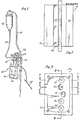
- Figure 1 illustrates an I.V. administration system including a volumetric infusion pump with an automatic air-in-line fluid detector of the present invention;
- Figure 2 illustrates a front view of an external portion of the automatic detector of the present invention which portion receives the fluid line;
- Figure 3 illustrates a left side view of the portion of the automatic detector of Figure 2;
- Figure 4 illustrates a right side view of the portion of the automatic detector of Figure 2;
- Figure 5 illustrates a cross-sectional view of the portion of the automatic detector taken along lines 5-5 of Figure 3;
- Figure 6 illustrates a cross-sectional view of the portion of the automatic detector taken along lines 6-6 of Figure 3;
- Figure 7 illustrates a cross-sectional view of the portion of the automatic detector taken along lines 7-7 of Figure 3; and
- Figure 8a, b, c and d successively illustrate a cross-sectional view of the portion of the automatic detector taken along lines 8-8 of Figure 3 or Figure 4 as an air bubble progresses through an associated fluid line.
- In Figure 1 a
volumetric pump 10 is shown.Pump 10 may include an automatic air-in-line fluid detector having asupport portion 12 for receiving afluid line 22. As seen in Figure 1, pump 10 is mounted on apole 14 and a bottle offluid 16 to be infused is supported above thepump 10. Fluid from thebottle 16 is allowed to flow downward through afluid line 18 and enter adisposable cassette 20. Duringnormal operation pump 10 provides for an accurate pumping of the fluid from thecassette 20 to anoutside fluid line 22. - The
pump 10 may include a pair of dials, such asdials fluid line 22 and the volume of fluid which is to flow through theline 22 to the patient. At the end of theline 22 is provided means 28 for allowing infusion of the fluid to the patient. For example, means 28 may include a hypodermic needle which is used to infuse fluid into the vein of the patient. Thepump 10 may be of the type disclosed in U.S. Patent No. 3,985,133, which is assigned to the same assignee as the instant application. It is to be appreciated, however, that the automatic air-in-line fluid detector of the present invention may be used with other types of fluid pumps. Further, the automatic air-in-line detector of the present invention may be used with any type of gravity feed means for infusing fluid to a patient, such as controller. - The
fluid line 22 passing from thecassette 20 is positioned within achannel 56 in thesupport portion 12. Thesupport 12 includes a plurality of detector elements which in combination with appropriate electronic circuitry provide for an automatic detection of air-in-line. - Figures 2 through 7 show the details of the construction of the
support 12. As illustrated,support 12 includes a base 50 having an open front with a pair of taperedsides circular channel 56 which channel receives thefluid line 22 in position for detection of the contents passing throughline 22. A plurality of light emitters and light detectors are disposed along thechannel 56 on opposite sides of the chaannel to provide for the detection of air-in-line regardless of the opacity of the fluid normally in theline 22. - As best seen in Figure 4 and Figures 8a, b, c and d, a plurality of
light emitters emitter openings base 50 which optically communicate with one side of thechannel 56.Base 50 is also provided with arecess portion 68 to provide access to theopenings light emitters - On the opposite side of the
channel 56, as seen in Figure 4 and Figures 8a, b, c and d, a plurality oflight detectors detector openings area 80 inbase 50 and thechannel 56. Light detectors or photo transistors of a type well known in the art, such as Model No. SPX-2532 manufactured by Spectronics, will serve the purposes of the present invention. - Important to the present invention is that the
detectors openings detectors detectors detectors emitters emitters detectors - It should also be noted that the
emitters respective detectors fluid line 22, such as shown foremitter 30 anddetector 40 in Figure 7. Thus, as previously discussed, if an opaque fluid is present in the portion offluid line 22 positioned in thechannel 56, little or no light energy passes from one of the emitters to one of the detectors. If, on the other hand, a transparent fluid or air is present in the portion offluid line 22 positioned in thechannel 56, light energy freely passes from an emitter to its complementary detector arranged as shown in Figure 7. The emitters and detectors positioned inopenings - For purposes discussed previously,
emitters detectors emitter 34 in opening 62 is arranged to direct light energy through thechannel 56 but at a rearward position of thechannel 56. In addition, thedetector 44 is set at an angle. When there is a transparent fluid in theline 22, the light fromemitter 34 is refracted by the fluid to pass todetector 44. However, if air is intube 22, the light fromemitter 34 is not refracted and it does not pass to thedetector 44. The operation of theemitter 32 anddetector 42 in theopenings channel 56. The positioning of these emitters and detectors ensures detection on both sides of thefluid line 22 and enables the detector to detect larger air bubbles but allow small air bubbles which are not harmful to pass. - The operation of the present invention is best understood by initially considering the operation of only two optical ON-OFF sensors included in the preferred embodiment of the present invention. For this purpose, the
light emitters detectors light emitter 30 andlight detector 40 together comprise a firstoptical sensor 90. Also, as seen in Figure 8b,light emitter 32 andlight detector 42 together comprise a secondoptical sensor 92. As shown in Figures 8a, b, c and d, firstoptical sensor 90 is positioned upstream from secondoptical sensor 92. Accordingly, the leading edge of an air bolus in thefluid line 22 will pass firstoptical sensor 90 before passing secondoptical sensor 92. - As previously stated,
detector 40 of firstoptical sensor 90 is adjusted to a higher light intensity than isdetector 42 of secondoptical sensor 92. In other words, as light intensity dims,optical sensor 90 will change to an OFF condition (no detection of light) beforeoptical sensor 92. Also, as previously disclosed, it is necessary that firstoptical sensor 90 be arranged in a manner as shown in Figure 7 for a direct light path diametrically through the lumen of the I.V.tube 22. This direct path arrangement minimizes or eliminates any refraction of the light path by fluid in the line. Additionally, it is important that secondoptical sensor 92 be arranged as shown in Figure 5 or Figure 6 so that the passage of light fromemitter 32 todetector 42 is dependent upon a refracted light beam. As can be appreciated by the skilled artisan, secondoptical sensor 92 will not pass light when there is either air influid line 22, since air does not effectively refract light, or when there is a sufficiently opaque fluid in theline 22 which will not effectively pass the light ray. - The logic circuitry required in a microprocessor (not shown) to accomplish the purposes of the present invention can be best understood by reference to Logic tables. It is understood that various microprocessor programs can be generated by the skilled artisan to accomplish the purposes of the present invention in accordance with the disclosed logic. Although several microprocessors are available, for the purposes of the preferred embodiment, microprocessors of the type 8051 manufactured by Intel Corporation and identified by MCS Series are preferred.

- Table I assumes an initial condition wherein a clear fluid is passing through the
fluid line 22 in a direction indicated by thearrow 88 in Figures 8a, b, c and d. Under this condition, bothfirst sensor 90 andsecond sensor 92 are in the ON condition indicating that light from the emitter of each optical sensor is being sensed by the detector of each sensor. Also shown in Table I is the effect of an increase in the opalescence or opacity of the fluid passing through the I.V.line 22. Under this situation,sensor 90 will change to the OFF condition beforesensor 92 becausesensor 92 requires less light intensity for the ON condition than doessensor 90. In this situation there should be no alarm. Another situation which can affectsensors fluid line 22 is a change in the ambient light. An increase in ambient light will have no effect upon eithersensor 90 orsensor 92 since bothdetectors sensor 90 will be the first to change to the OFF position. It should be appreciated that this may happen although there is still fluid within the fluid line. Again, there should be no alarm. In the situation where there is an air bubble in the clear fluid in theline 22,sensor 90 will remain ON as the bubble passes because the presence of air in theline 22 does not disrupt its light path. On the other hand, as the bubble passessensor 92, light from itsemitter 32 is no longer refracted due to the absence of fluid in the line. Sincedetector 42 no longer senses light from theemitter 32,sensor 92 turns OFF. In this situation, i.e.,sensor 90 ON andsensor 92 OFF, there is air in the line and an alarm should be indicated. - Using this information, a logic program could be established in a microprocessor by a skilled artisan whereby an alarm is activated whenever
sensors sensor 92 turns to an OFF condition. Logic circuitry can be established to ignore changes insensor 90 from ON to OFF which would only indicate either increased opacity influid line 22 or decrease in ambient light. Indeed, even if operation is such thatsensor 90 is OFF andsensor 92 is ON, the passage of an air bubble will first changesensor 90 to an ON condition before affectingsensor 92. Thus, for at least an instant, there will be a return to the initial ON-ON condition. In this manner, when an initially clear fluid is in the line, it can be seen that the apparatus is rendered insensitive to the opalescence of a fluid passing through the LV. tube and to a decrease in the ambient liqht level.
- Table 11 is arranged to show a situation wherein the inline fluid is initially opaque. When starting with an opaque fluid, a decrease in the opalescence or opacity of the fluid causes the second sensor,
sensor 92, to turn ON beforefirst sensor 90 because it requires less light to be activated. As also seen in Table II, an effective increase in ambient light level may also causesensor 92 to turn ON for the same reason. As expected, when opaque fluid is inline 22, a decrease in the ambient light has no effect onsensors sensor 90 changes to an ON condition because the air bolus or bubble allows for the passage of light on the direct optical path betweenemitter 30 anddetector 40. As air passessensor 92, it will remain OFF because the air will not refract the light fromemitter 32 so as to be received byoptical detector 42. Again, as in the situation with an initially clear fluid, air in the line causessensor 90 to be ON andsensor 92 OFF. An alarm condition is indicated. - A comparison of Table I and Table II indicates that from either an ON-ON or an OFF-OFF condition for
sensors sensor 90 and an OFF condition forsensor 92 indicates air-in-line. As will be appreciated by those skilled in the art, all other sequences of changes in the sensors can be neglected by the logic circuitry in a manner that only the air-in-line condition activates an alarm or stops operation of the infusion apparatus.
- For completeness, Table III indicates the situation in which an opalescent or translucent fluid is initially present in the
fluid line 22. As seen in Table III, the relative conditions ofsensor sensor 90 to the ON condition andsensor 92 to the OFF condition to alarm the system. - Redundancy can be built into the system by selectively providing additional sensors arranged in a sequence to provide for the creation of signals in accordance with the logic discussed above. More specifically, in the preferred embodiment, a plurality of light emitters and their respective light detectors arranged as shown in Figures 8a, b, c and d comprise a series of optical sensors. Further, it can be appreciated that
detectors tube 22 fromemitters detectors emitters tube 22. - A discussion of the switching logic for
light emitters respective detectors detectors detector 44 is selected to have higher light sensitivity. Accordingly, under the samelighting conditions detector 44 will detect light at lower intensity levels thandetector 46. This, of course, permits a similar insensitivity for either fluid opacity or changes in ambient light levels to the insensitivities previously discussed forsensors - For the present invention, the logic circuitry always considers the ON-OFF conditions of any two adjacent detectors. With standard I.V. tubes which have relatively small inner diameters, it has been determined that air bubbles that affect only one optical sensor at a time pose negligible risk to the patient. As will be appreciated by the skilled artisan, for any given size of I.V. fluid line the spacing of the optical sensors along the
fluid line 22 can be adjusted to detect larger or smaller air bubbles according to the desires of the operator.
Claims (12)
Applications Claiming Priority (2)
| Application Number | Priority Date | Filing Date | Title |
|---|---|---|---|
| US716862 | 1985-03-28 | ||
| US06/716,862 US4658244A (en) | 1985-03-28 | 1985-03-28 | Air-in-line detector |
Publications (3)
| Publication Number | Publication Date |
|---|---|
| EP0196822A2 EP0196822A2 (en) | 1986-10-08 |
| EP0196822A3 EP0196822A3 (en) | 1987-07-29 |
| EP0196822B1 true EP0196822B1 (en) | 1990-09-19 |
Family
ID=24879755
Family Applications (1)
| Application Number | Title | Priority Date | Filing Date |
|---|---|---|---|
| EP86302005A Expired - Lifetime EP0196822B1 (en) | 1985-03-28 | 1986-03-19 | Air-in-line detector |
Country Status (6)
| Country | Link |
|---|---|
| US (1) | US4658244A (en) |
| EP (1) | EP0196822B1 (en) |
| JP (1) | JPS61270641A (en) |
| AU (1) | AU582634B2 (en) |
| CA (1) | CA1237795A (en) |
| DE (1) | DE3674230D1 (en) |
Families Citing this family (49)
| Publication number | Priority date | Publication date | Assignee | Title |
|---|---|---|---|---|
| GB8424101D0 (en) * | 1984-09-24 | 1984-10-31 | Vi Tal Hospital Products Ltd | Air-in-line detector |
| FR2599496B1 (en) * | 1986-05-28 | 1992-02-14 | Mms | BUBBLE DETECTOR IN A LIQUID CIRCUIT |
| US4859864A (en) * | 1987-05-07 | 1989-08-22 | Becton, Dickinson And Company | Sensor and method for detecting the presence of air bubbles in liquid |
| US4884065A (en) * | 1988-06-13 | 1989-11-28 | Pacesetter Infusion, Ltd. | Monitor for detecting tube position and air bubbles in tube |
| JPH0638853B2 (en) * | 1988-07-04 | 1994-05-25 | シャープ株式会社 | Bubble detector for infusion pump |
| US4931774A (en) * | 1988-08-17 | 1990-06-05 | Dickey-John Corporation | Liquid-vapor change of phase detector |
| US4981467A (en) * | 1990-02-27 | 1991-01-01 | Baxter International Inc. | Apparatus and method for the detection of air in fluid delivery systems |
| US5382232A (en) * | 1992-03-13 | 1995-01-17 | Ivac Corporation | Infusion system with air-in-line clear function |
| FR2710538B1 (en) * | 1993-09-30 | 1995-12-01 | Becton Dickinson Co | Method and device for detecting bubbles in an infusion line. |
| GB9402256D0 (en) * | 1994-02-05 | 1994-03-30 | Danby Medical Ltd | Dual sensor air-in-line detector |
| DE19500154C1 (en) * | 1995-01-04 | 1996-10-17 | Fritz Giebler Gmbh | Infusion tube for an infusion device with a bubble detector |
| US5868710A (en) | 1996-11-22 | 1999-02-09 | Liebel Flarsheim Company | Medical fluid injector |
| DE69833367T2 (en) | 1997-04-29 | 2006-08-03 | Medtronic, Inc., Minneapolis | OPTICAL DETECTION AND QUANTIFICATION OF MICROBUBBLES IN BLOOD |
| US6070761A (en) * | 1997-08-22 | 2000-06-06 | Deka Products Limited Partnership | Vial loading method and apparatus for intelligent admixture and delivery of intravenous drugs |
| US6616633B1 (en) * | 1997-09-19 | 2003-09-09 | Alaris Medical Systems, Inc. | Apparatus and method for air-in-line detection |
| DE19813629A1 (en) * | 1998-03-27 | 1999-10-07 | Alexander Kosellek | Safety arrangement for electrical water heater, and its air and water flows |
| US6162194A (en) * | 1998-05-20 | 2000-12-19 | Apollo Camera, Llc | Surgical irrigation apparatus and methods for use |
| US6142008A (en) * | 1998-06-12 | 2000-11-07 | Abbott Laboratories | Air bubble sensor |
| US6231320B1 (en) | 1998-06-12 | 2001-05-15 | Abbott Laboratories | Drug infusion pumping cassette latching mechanism |
| ITMI20031715A1 (en) * | 2003-09-05 | 2005-03-06 | Dideco Spa | CONTROL DEVICE IN THE DIFFERENTIATED COLLECTION OF THE |
| US7661294B2 (en) * | 2007-09-21 | 2010-02-16 | Cosense, Inc. | Non-invasive multi-function sensor system |
| KR101861192B1 (en) | 2007-02-27 | 2018-05-28 | 데카 프로덕츠 리미티드 파트너쉽 | Hemodialysis apparatus and methods |
| US9028691B2 (en) | 2007-02-27 | 2015-05-12 | Deka Products Limited Partnership | Blood circuit assembly for a hemodialysis system |
| US7981082B2 (en) * | 2007-08-21 | 2011-07-19 | Hospira, Inc. | System and method for reducing air bubbles in a fluid delivery line |
| CA2698947C (en) * | 2007-10-11 | 2017-12-12 | Ecolab Inc. | Optical product detection sensor |
| US7924424B2 (en) * | 2007-10-11 | 2011-04-12 | Ecolab Usa Inc. | Optical product detection sensor |
| US8517990B2 (en) | 2007-12-18 | 2013-08-27 | Hospira, Inc. | User interface improvements for medical devices |
| KR101863753B1 (en) | 2008-01-23 | 2018-06-04 | 데카 프로덕츠 리미티드 파트너쉽 | Pump cassette and methods for use in medical treatment system using a plurality of fluid lines |
| US11833281B2 (en) | 2008-01-23 | 2023-12-05 | Deka Products Limited Partnership | Pump cassette and methods for use in medical treatment system using a plurality of fluid lines |
| CA3024418A1 (en) * | 2010-07-07 | 2012-01-12 | Matthew J. Finch | Medical treatment system and methods using a plurality of fluid lines |
| US9724458B2 (en) | 2011-05-24 | 2017-08-08 | Deka Products Limited Partnership | Hemodialysis system |
| CA2844807C (en) | 2011-08-19 | 2022-07-26 | Hospira, Inc. | Systems and methods for a graphical interface including a graphical representation of medical data |
| US10022498B2 (en) | 2011-12-16 | 2018-07-17 | Icu Medical, Inc. | System for monitoring and delivering medication to a patient and method of using the same to minimize the risks associated with automated therapy |
| JP6306566B2 (en) | 2012-03-30 | 2018-04-04 | アイシーユー・メディカル・インコーポレーテッド | Air detection system and method for detecting air in an infusion system pump |
| ES2743160T3 (en) | 2012-07-31 | 2020-02-18 | Icu Medical Inc | Patient care system for critical medications |
| WO2014190264A1 (en) | 2013-05-24 | 2014-11-27 | Hospira, Inc. | Multi-sensor infusion system for detecting air or an occlusion in the infusion system |
| ES2838450T3 (en) | 2013-05-29 | 2021-07-02 | Icu Medical Inc | Infusion set that uses one or more sensors and additional information to make an air determination relative to the infusion set |
| AU2014274122A1 (en) | 2013-05-29 | 2016-01-21 | Icu Medical, Inc. | Infusion system and method of use which prevents over-saturation of an analog-to-digital converter |
| JP6636442B2 (en) | 2014-02-28 | 2020-01-29 | アイシーユー・メディカル・インコーポレーテッド | Infusion systems and methods utilizing dual wavelength optical in-pipe air detection |
| AU2015266706B2 (en) | 2014-05-29 | 2020-01-30 | Icu Medical, Inc. | Infusion system and pump with configurable closed loop delivery rate catch-up |
| US11344668B2 (en) | 2014-12-19 | 2022-05-31 | Icu Medical, Inc. | Infusion system with concurrent TPN/insulin infusion |
| US10850024B2 (en) | 2015-03-02 | 2020-12-01 | Icu Medical, Inc. | Infusion system, device, and method having advanced infusion features |
| EP3454922B1 (en) | 2016-05-13 | 2022-04-06 | ICU Medical, Inc. | Infusion pump system with common line auto flush |
| CA3027176A1 (en) | 2016-06-10 | 2017-12-14 | Icu Medical, Inc. | Acoustic flow sensor for continuous medication flow measurements and feedback control of infusion |
| US10089055B1 (en) | 2017-12-27 | 2018-10-02 | Icu Medical, Inc. | Synchronized display of screen content on networked devices |
| US11278671B2 (en) | 2019-12-04 | 2022-03-22 | Icu Medical, Inc. | Infusion pump with safety sequence keypad |
| WO2022020184A1 (en) | 2020-07-21 | 2022-01-27 | Icu Medical, Inc. | Fluid transfer devices and methods of use |
| US11135360B1 (en) | 2020-12-07 | 2021-10-05 | Icu Medical, Inc. | Concurrent infusion with common line auto flush |
| AU2022226664A1 (en) * | 2021-02-26 | 2023-09-07 | Bayer Healthcare Llc | Air detection and measurement system for fluid injector |
Family Cites Families (21)
| Publication number | Priority date | Publication date | Assignee | Title |
|---|---|---|---|---|
| US2835252A (en) * | 1955-06-06 | 1958-05-20 | James B Mcfadyen | Monitor apparatus for blood transfusions |
| BE162295A (en) * | 1967-02-13 | |||
| US3812482A (en) * | 1973-02-26 | 1974-05-21 | Primary Childrens Hospital | Air emboli detector |
| US3898637A (en) * | 1973-07-27 | 1975-08-05 | Eugene B Wolstenholme | Detection means for gas entering human blood system from extra-corporeal tubing |
| GB1482350A (en) * | 1973-09-17 | 1977-08-10 | Atomic Energy Authority Uk | Ultra sonic testing |
| US3935876A (en) * | 1974-11-15 | 1976-02-03 | Renal Systems, Inc. | Air leak detector |
| US3993061A (en) * | 1975-02-28 | 1976-11-23 | Ivac Corporation | Syringe pump drive system and disposable syringe cartridge |
| US4126132A (en) * | 1975-07-28 | 1978-11-21 | Andros Incorporated | Intravenous and intra arterial delivery system |
| US4114144A (en) * | 1976-08-12 | 1978-09-12 | Imed Corporation | Automatic air-in-line fluid detector |
| GB1556461A (en) * | 1976-09-13 | 1979-11-28 | Atomic Energy Authority Uk | Detection of bubbles in a liquid |
| US4138879A (en) * | 1977-08-22 | 1979-02-13 | Tif Instruments, Inc. | Sightless bubble detector |
| US4210138A (en) * | 1977-12-02 | 1980-07-01 | Baxter Travenol Laboratories, Inc. | Metering apparatus for a fluid infusion system with flow control station |
| US4256437A (en) * | 1978-02-01 | 1981-03-17 | Stewart Naumann Laboratories, Inc. | Peristaltic infusion pump and method |
| US4280495A (en) * | 1978-11-24 | 1981-07-28 | Sarns, Inc. | Air emboli detection |
| US4265240A (en) * | 1979-04-16 | 1981-05-05 | Imed Corporation | Apparatus for providing a controlled introduction of intravenous fluid to a patient |
| US4344429A (en) * | 1979-12-13 | 1982-08-17 | Baxter Travenol Laboratories, Inc. | Bubble detector with feedback circuit for improved sensitivity |
| US4312341A (en) * | 1979-12-13 | 1982-01-26 | Baxter Travenol Laboratories, Inc. | Bubble detector |
| US4366384A (en) * | 1980-06-18 | 1982-12-28 | Cutter Laboratories, Inc. | Air bubble detector |
| US4367736A (en) * | 1980-08-25 | 1983-01-11 | Baxter Travenol Laboratories, Inc. | System for detecting bubble formation in clear and opaque fluids |
| US4384578A (en) * | 1981-04-16 | 1983-05-24 | The United States Of America As Represented By The Administrator Of The National Aeronautics And Space Administration | Bio-medical flow sensor |
| GB8424101D0 (en) * | 1984-09-24 | 1984-10-31 | Vi Tal Hospital Products Ltd | Air-in-line detector |
-
1985
- 1985-03-28 US US06/716,862 patent/US4658244A/en not_active Expired - Lifetime
-
1986
- 1986-02-24 CA CA000502538A patent/CA1237795A/en not_active Expired
- 1986-03-19 DE DE8686302005T patent/DE3674230D1/en not_active Expired - Fee Related
- 1986-03-19 EP EP86302005A patent/EP0196822B1/en not_active Expired - Lifetime
- 1986-03-24 AU AU55054/86A patent/AU582634B2/en not_active Ceased
- 1986-03-27 JP JP61069712A patent/JPS61270641A/en active Granted
Also Published As
| Publication number | Publication date |
|---|---|
| DE3674230D1 (en) | 1990-10-25 |
| JPS61270641A (en) | 1986-11-29 |
| AU582634B2 (en) | 1989-04-06 |
| EP0196822A3 (en) | 1987-07-29 |
| CA1237795A (en) | 1988-06-07 |
| EP0196822A2 (en) | 1986-10-08 |
| AU5505486A (en) | 1986-10-02 |
| JPH0545176B2 (en) | 1993-07-08 |
| US4658244A (en) | 1987-04-14 |
Similar Documents
| Publication | Publication Date | Title |
|---|---|---|
| EP0196822B1 (en) | Air-in-line detector | |
| US4114144A (en) | Automatic air-in-line fluid detector | |
| US4857050A (en) | Ratiometric air-in-line detector | |
| US6531708B1 (en) | Optical bubble detection system | |
| US4496346A (en) | Infusion monitoring apparatus | |
| US4559454A (en) | Bubble detecting infusion apparatus | |
| US4829448A (en) | Air-in-line detector | |
| CA2102424C (en) | Drop detection method and apparatus | |
| JP4261774B2 (en) | Fluid conduit monitoring device | |
| KR0157986B1 (en) | Apparatus and method for the detection of air in fluid delivery systems | |
| US8052642B2 (en) | Pumping apparatus with secure loading features | |
| CA1240755A (en) | Empty container detector with drop sensor | |
| CA1157291A (en) | Air bubble detector | |
| US8142404B2 (en) | Controller for pumping apparatus | |
| US8052643B2 (en) | Enteral feeding set and interlock device therefor | |
| EP2736564B1 (en) | An infrared reflective air-in-line sensor system | |
| US5200627A (en) | Apparatus and method for monitoring flow of infusion liquid | |
| EP0042400A4 (en) | Bubble detector in a flow metering apparatus. | |
| KR100344609B1 (en) | Dual Sensor Line Air Detector | |
| EP0125122A2 (en) | Parenteral solution delivery system | |
| JPH0642180Y2 (en) | Liquid level detector |
Legal Events
| Date | Code | Title | Description |
|---|---|---|---|
| PUAI | Public reference made under article 153(3) epc to a published international application that has entered the european phase |
Free format text: ORIGINAL CODE: 0009012 |
|
| AK | Designated contracting states |
Kind code of ref document: A2 Designated state(s): DE FR GB |
|
| PUAL | Search report despatched |
Free format text: ORIGINAL CODE: 0009013 |
|
| AK | Designated contracting states |
Kind code of ref document: A3 Designated state(s): DE FR GB |
|
| 17P | Request for examination filed |
Effective date: 19871007 |
|
| RAP1 | Party data changed (applicant data changed or rights of an application transferred) |
Owner name: FISHER SCIENTIFIC GROUP INC. |
|
| 17Q | First examination report despatched |
Effective date: 19890704 |
|
| GRAA | (expected) grant |
Free format text: ORIGINAL CODE: 0009210 |
|
| AK | Designated contracting states |
Kind code of ref document: B1 Designated state(s): DE FR GB |
|
| REF | Corresponds to: |
Ref document number: 3674230 Country of ref document: DE Date of ref document: 19901025 |
|
| ET | Fr: translation filed | ||
| RAP2 | Party data changed (patent owner data changed or rights of a patent transferred) |
Owner name: IMED CORPORATION |
|
| PLBE | No opposition filed within time limit |
Free format text: ORIGINAL CODE: 0009261 |
|
| STAA | Information on the status of an ep patent application or granted ep patent |
Free format text: STATUS: NO OPPOSITION FILED WITHIN TIME LIMIT |
|
| 26N | No opposition filed | ||
| REG | Reference to a national code |
Ref country code: FR Ref legal event code: GC |
|
| REG | Reference to a national code |
Ref country code: GB Ref legal event code: 732E |
|
| REG | Reference to a national code |
Ref country code: FR Ref legal event code: TP Ref country code: FR Ref legal event code: CD |
|
| PGFP | Annual fee paid to national office [announced via postgrant information from national office to epo] |
Ref country code: FR Payment date: 20000310 Year of fee payment: 15 |
|
| PGFP | Annual fee paid to national office [announced via postgrant information from national office to epo] |
Ref country code: GB Payment date: 20000315 Year of fee payment: 15 |
|
| PGFP | Annual fee paid to national office [announced via postgrant information from national office to epo] |
Ref country code: DE Payment date: 20000318 Year of fee payment: 15 |
|
| PG25 | Lapsed in a contracting state [announced via postgrant information from national office to epo] |
Ref country code: GB Free format text: LAPSE BECAUSE OF NON-PAYMENT OF DUE FEES Effective date: 20010319 |
|
| GBPC | Gb: european patent ceased through non-payment of renewal fee |
Effective date: 20010319 |
|
| PG25 | Lapsed in a contracting state [announced via postgrant information from national office to epo] |
Ref country code: FR Free format text: LAPSE BECAUSE OF NON-PAYMENT OF DUE FEES Effective date: 20011130 |
|
| REG | Reference to a national code |
Ref country code: FR Ref legal event code: ST |
|
| PG25 | Lapsed in a contracting state [announced via postgrant information from national office to epo] |
Ref country code: DE Free format text: LAPSE BECAUSE OF NON-PAYMENT OF DUE FEES Effective date: 20020301 |