EP0195842B1 - Spray cleaning device - Google Patents
Spray cleaning device Download PDFInfo
- Publication number
- EP0195842B1 EP0195842B1 EP85106922A EP85106922A EP0195842B1 EP 0195842 B1 EP0195842 B1 EP 0195842B1 EP 85106922 A EP85106922 A EP 85106922A EP 85106922 A EP85106922 A EP 85106922A EP 0195842 B1 EP0195842 B1 EP 0195842B1
- Authority
- EP
- European Patent Office
- Prior art keywords
- nozzle
- cleaning
- cylinder
- drum
- water
- Prior art date
- Legal status (The legal status is an assumption and is not a legal conclusion. Google has not performed a legal analysis and makes no representation as to the accuracy of the status listed.)
- Expired
Links
Images




Classifications
-
- G—PHYSICS
- G05—CONTROLLING; REGULATING
- G05B—CONTROL OR REGULATING SYSTEMS IN GENERAL; FUNCTIONAL ELEMENTS OF SUCH SYSTEMS; MONITORING OR TESTING ARRANGEMENTS FOR SUCH SYSTEMS OR ELEMENTS
- G05B19/00—Program-control systems
- G05B19/02—Program-control systems electric
- G05B19/18—Numerical control [NC], i.e. automatically operating machines, in particular machine tools, e.g. in a manufacturing environment, so as to execute positioning, movement or co-ordinated operations by means of program data in numerical form
- G05B19/19—Numerical control [NC], i.e. automatically operating machines, in particular machine tools, e.g. in a manufacturing environment, so as to execute positioning, movement or co-ordinated operations by means of program data in numerical form characterised by positioning or contouring control systems, e.g. to control position from one programmed point to another or to control movement along a programmed continuous path
- G05B19/40—Open loop systems, e.g. using stepping motor
-
- E—FIXED CONSTRUCTIONS
- E03—WATER SUPPLY; SEWERAGE
- E03D—WATER-CLOSETS OR URINALS WITH FLUSHING DEVICES; FLUSHING VALVES THEREFOR
- E03D9/00—Sanitary or other accessories for lavatories ; Devices for cleaning or disinfecting the toilet room or the toilet bowl; Devices for eliminating smells
- E03D9/08—Devices in the bowl producing upwardly-directed sprays; Modifications of the bowl for use with such devices ; Bidets; Combinations of bowls with urinals or bidets; Hot-air or other devices mounted in or on the bowl, urinal or bidet for cleaning or disinfecting
-
- G—PHYSICS
- G05—CONTROLLING; REGULATING
- G05B—CONTROL OR REGULATING SYSTEMS IN GENERAL; FUNCTIONAL ELEMENTS OF SUCH SYSTEMS; MONITORING OR TESTING ARRANGEMENTS FOR SUCH SYSTEMS OR ELEMENTS
- G05B2219/00—Program-control systems
- G05B2219/30—Nc systems
- G05B2219/37—Measurements
- G05B2219/37322—Derive position from frequency power supply
Definitions
- This invention relates to a device for moving a nozzle in a spray cleaning device for washing the anus and functioning as a bidet.
- spray cleaning device as herein used means an apparatus including a tank for cleaning water, a cleaning nozzle which is movable between its retracted position and its cleaning position, a system for heating the cleaning water, a system for supplying the heated cleaning water, a system for moving the nozzle and devices for controlling those systems, and provided at the rear end of a water closet for directing a jet of heated cleaning water toward the private parts through the nozzle in its cleaning position.
- the nozzle has two cleaning positions, i.e., the position for cleaning the anus and the position for functioning as a bidet.
- the nozzle is slidably disposed in a cylinder and the cleaning water is introduced into the cylinder to push the nozzle out of the cylinder to either of its cleaning positions.
- a spring is connected to the nozzle for urging the nozzle back to its retracted position in the cylinder.
- the other arrangement employs a motor which is rotatable in either direction for moving the nozzle out of, or into, a cylinder. This arrangement will hereunder be described with reference to FIGURE 16.
- the cylinder 101 is secured in a casing 100 located adjacent to the rear end of a toilet stool (not shown).
- the nozzle 102 which comprises a tubular body, is axially slidable in the cylinder 101.
- the electric motor 103 is provided adjacent to the proximal end of the cylinder 101 for moving the nozzle 102 forward or backward.
- the motor 103 has an output shaft 104to which a cylindrical drum 105 is secured.
- a leaf spring 106 has one end wound on, and fastened to, the outer cylindrical surface of the drum 105. The other end of the spring 106 is connected to the proximal end of the nozzle 102.
- the output shaft 104 of the motor 103 is rotatable in two directions and the manner of the rotations of the output shaft 104 causes the reciprocal motion of the nozzle 102 in the cylinder 101.
- the nozzle 102 When the nozzle 102 is brought to its cleaning position, it directs a jet of cleaning water toward the private parts of a person using the toilet through its end openings 107.
- the positioning of the conventional nozzle 102 structure is effected by a feedback control system including a sensor of, for example, the magnetic or optical type which is located in a position for monitoring the motion of the nozzle 102. The sensor detects the amount of motion of the nozzle 102 and transmits a corresponding signal to the motor 103 to turn the power circuit of the motor 103 on or off.
- the system relying on the pressure of the cleaning water for positioning the nozzle has the disadvantage that if the water pressure is lower than a predetermined level, the nozzle fails to reach its designated cleaning position and accomplish its proper cleaning function. If the nozzle is of thetype having two cleaning positionsforthe anus and for the use as a bidet, respectively, its internal water passages formed in the nozzle 102 itself are complicated and the size of the nozzle 102 is undesirably enlarged.
- the system employing the motor 103 for moving the nozzle 102 and the sensor for detecting and positioning it has the disadvantage that its nozzle positioning accuracy depends on the performance of the sensor. If the sensor fails to function accurately, the nozzle 102 fails to reach its designated cleaning position and also to accomplish its proper cleaning operation as mentioned above.
- the sensor requires a complicated job of assembly including wiring connection between the motor 103 and the control system and mounting in a predetermined narrow space, and the control system also becomes complicated.
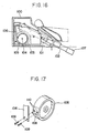
- the drum 105 has, as shown in FIGURE 17, formed on its outer cylindrical surface a shoulder 108 and threaded holes 110 provided in the vicinity of the shoulder 108 for receiving screws 109 for securing the leaf spring 106.
- the outer cylindrical surface of the drum 105 on which the leaf spring 106 is wound does not have a uniform curvature.
- the leaf spring 106 is wound on the surface of the drum 105 and unwound therefrom repeatedly.
- Another problem that the conventional part cleaning device involves is due to the fact that the distal end portion of the nozzle 102 which is provided with the openings 107 projects from the cylinder 101 even when the nozzle 102 is in its retracted position.
- the projecting distal end portion of the nozzle 102 is always liable to contamination by dirty liquid or matter, whether the nozzle 102 may be in its cleaning or retracted position.
- the dirty liquid and matter are likely to form powder on the projecting end portion of the nozzle 102 and in its openings 107 and thereby to block the openings 107. They have an objectionable odour, and contaminate cleaning water.
- EP-A-0,074,883 relates to a mechanism for rectilinear translation of a slidable body comprising two pulleys and two driving beltswherein each belt with one end is fixed to a pulley and with the other end is fixed to the slidable body.
- the belts are driven by an electric motor.
- the first object is attained by an improved device for driving a slidable nozzle in a spray cleaning device which comprises a cylinder, a nozzle having at a distal end thereof openings through which cleaning water is directed outwardly, an electric motor for moving the nozzle axially in either direction in the cylinder, a drum secured to the output shaft of the motor and a leaf spring connecting the drum and the nozzle, and characterized in that the drum comprises a main body portion having a sectoral recess and a sectoral insert portion fitted in the sectoral recess and having an arcuate outer peripheral surface defining precision cylindrical drum surface with the outer peripheral surface of the main body portion, and that one end of the leaf spring is secured between the mutually fitting surfaces of the main body and sectoral insert portions.
- the amount of the spring which is wound or unwound reflects the amount and angle of the rotation of the output shaft of the motor correctly, and the amount and angle of the rotation of the output shaft are transmitted to the nozzle highly accurately.
- the second object is attained by a device including a nozzle having a flattened nozzle head and adapted for its complete retraction into a cylinder, a first packing member provided in the cylinder for sealing the peripheral surface of the nozzle when it is in its retracted position, a second packing member provided between the first packing member and the distal end of the cylinder and surrounding the nozzle head portion, and a cleaning water feed line connected to the cylinder between the first and second packing members, the nozzle head being temporarily stopped in a position projecting out of the distal end portion of the cylinder immediately before its arrival at its cleaning position and immediately after its departure therefrom so that the cleaning water may be discharged through an annular passage between the second packing member and the nozzle head portion for cleaning the distal end portion of the cylinder and the nozzle head.
- Switches for starting the cleaning operation of the anus and the function as a bidet are provided in a control panel for a part cleaning device. If either of those switches is turned on, the nozzle is temporarily stopped in a position suitable for the 'self-cleaning of the nozzle head.
- the efec- tromagnetic valve or pump disposed in the cleaning water feed line works for a brief period of time to supply water from a hot water storage tank to the annular passage so that it may clean the nozzle head and the distal end of portion the cylinder before it is discharged into a toilet.
- the stop switch provided in the control panel is turned on, the nozzle starts retracting into the cylinder and stops temporarily at its self-cleaning position on its way again.
- the electromagnetic valve or pump works briefly and water is supplied from the hot water storage tank to the annular passage for cleaning the nozzle head itself and the distal end portion of the cylinder before the nozzle is moved to its completely retracted position in the cylinder.
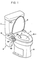
- FIGURE 1 A water closet provided with a part cleaning device A embodying this invention is shown in FIGURE 1 and comprises a toilet stool B, a flushing water tank C, a lavatory seat D and a lid E.
- the part cleaning device A comprises a base 1, a tank F for heating and storing cleaning water, a valve unit G for supplying the cleaning water, a hot air fan H for drying after cleaning and a nozzle device N located approximately in the center of the device and connected to the tank F by a cleaning water supply pipe P.
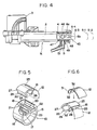
- the nozzle device N comprises a cylinder 2 secured on the base 1 and having a base end to which an electric motor 3 is integrally mounted, and a tubular nozzle body 4 provided axially movably in the cylinder 2, as shown in FIGURES 3 and 4.
- the motor 3 is a synchronous motor having an output shaft adapted for rotation synchronously with the frequency of a power source.
- the cylinder 2 is provided at the distal end thereof with an elbow 5 for connection to the cleaning water supply pipe P.
- the elbow 5 communicates with a water passage formed in the nozzle body 4 so that a jet of cleaning water may be directed outwardly through a plurality of first and second end openings 6a and 6b.
- a cylindrical drum 10 is secured to the output shaft 11 of the motor 3.
- a thin leaf spring 12 has its proximal end fastened to the drum 10 and the distal end of the leaf spring 12 is connected to the proximal end portion of the nozzle body 4.
- the drum 10 is formed from a synthetic resin. It comprises a main body portion 15 and an insert portion 16 for securing the leaf spring 12 integrally to the main body portion 15, as shown in FIGURE 5.
- the main body portion 15 has a central boss 17 secured about the output shaft 11, and a major arc-shaped cylindrical outer peripheral or rim surface 18 formed with a sectoral recess 19.
- the recess 19 defines a pair of radial walls 20 and 21 which is substantially equal in length to the width of the rim surface 18.
- the wall 20 has a groove 22 and the wall 21 also has a groove 23. Both of the grooves 22 and 23 are in parallel to the axis of the drum 10.
- the groove 23 has a positioning projection 24 approximately at the middle thereof.
- the insert portion 16 has a sectoral cross section and can be fitted in the sectoral recess 19.
- the insert portion 16 has an arcuate outer peripheral or rim surface 25 and a pair of radial walls 26 and 27.
- the rim surface 25 has a radius of curvature which is equal to that of the rim surface 18 of the main body portion 15, and the rim surfaces 18 and 25 form a precision cylindrical surface when the insert portion 16 is fitted in the main body portion 15.
- the wall 26 is formed on its outer surface with a pair of projections 28 for engaging the leaf spring 12, as shown in FIGURE 6.
- the wall 27 is provided at its radially inner edge with an outwardly directed flange 29 having approximately at the middle thereof a recess 30 in which the positioning projection 24 can be received.
- the leaf spring 12 is so bent prior to assembly as to closely fit the wall 26 of the insert portion 16 and the rim surfaces 18 and 25, and has the bent end portion 31 formed with a pair of holes 32 for receiving the projections 28 on the wall 26, as shown in FIGURE 6.
- the projections 28 extending through the holes 32 are fitted in the groove 22 of the wall 20 and the flange 29 is fitted in the groove 23 of the wall 21, as is obvious from FIGURE 5.
- the other end of the leaf spring 12 is connected by a pin 33 to the proximal end portion of the nozzle body 4, as shown in FIGURE 3.
- the leaf spring 12 is unwound from the rim surfaces 18 and 25 of the drum 10 to enable the nozzle body 4 to move forward to its cleaning position, and if the output shaft 11 of the motor 3 is rotated in the reverse direction, the leaf spring 12 is wound on the drum to enable the nozzle body 4 to return to its retracted position.
- the drum 10 has a precision cylindrical surface defined by the rim surfaces 18 and 25, the leaf spring 12 is subjected to uniform compression or tensile stress along its entire length when it is being either wound or unwound around the drum 10.
- the leaf spring 12 always works smoothly without being subjected to any localization of stress concentration or buckling, and therefore has long life and good durability.
- the leaf spring 12 is easy to be secured to the drum 10, as it is sufficient to fit the insert portion 16 in the main body portion 15.
- the nozzle body 4 is of the double-walled construction and comprises an outer tube 40 and an inner tube 41 disposed in the outer tube 40 coaxially therewith. Therefore, the nozzle body 4 has a first water passage 44 defined between the outer and inner tubes 40 and 41, having an annular cross section and leading to a nozzle head 43 at the outer end of the outer tube 40, and a second water passage 45 extending through the inner tube 41 and leading to the nozzle head 43.
- the nozzle head 43 is provided at its top with three or five first jet openings 6a and second jet openings 6b, though the number of those openings may have to be selected to provide the force of water required for cleaning the anus or the function for a bidet.
- the nozzle head 43 is flattened on the top and the bottom by a pair of shoulders 46 dividing it from the rest of the nozzle body 4.
- the cylinder 2 is provided inwardly of its outer distal end portion with a first packing member 47 and a second packing member 48 both having a Y-shaped cross section and surrounding the nozzle head 43 therebetween when the nozzle body 4 is in its completely retracted position.
- the packing members 47 and 48 and the shoulders 46 on the nozzle head 43 define an annular passage 49 in the cylinder 2.
- the annular passage 49 is connected to the passage 51 in the elbow 5 which is connected to the cleaning water supply pipe P leading to the tank F.
- the outer tube 40 has first and second water inlet openings (not shown) through which the annular passage 49 is connected to the first and second water passages 44 and 45 to supply cleaning water into the nozzle body 4 when it is in its cleaning position.
- the nozzle device N including the nozzle body 4 is secured to the base 1 in a casing W in such a way that the nozzle body 4 may be axially movable into the bowl B-1 of the toilet stool B.
- the jetting of the cleaning water from the nozzle device N is started by a cleaning start switch 53 and a start switch for a bidet 55 provided on a control panel 52 and stopped by a stop switch 54 also provided on the control panel 52.
- the nozzle body 4 can be stopped at three cleaning positions, i.e., the anus cleaning position S-1, the position for functioning as a bidet S-2 and self-cleaning position S-3.
- the nozzle body 4 When the nozzle body 4 is in its first stop position S-1 by the operation of the cleaning start switch 53, cleaning water flows from the annular passage 49 to the first jet openings 6a through the first inlet opening (not shown) and the first water passage 44 for cleaning the anus.
- the nozzle body 4 is in its second stop position S-2 by the operation of the start switch for a bidet 55, water flows from the annular passage 49 to the second jet openings 6b through the second inlet opening (not shown) and the second water passage 45 for the use as a bidet.
- the supply of cleaning water from the tank F may be effected by a known device, i.e., by an electromagnetic valve in the valve unit G if water is supplied directly, or by an electromagnetic pump (not shown) if it is supplied indirectly.
- the electromagnetic valve or pump is in operation for a brief period of time immediately after the nozzle body 4 has been temporarily stopped at its self-cleaning position S ⁇ 3, and immediately after it has been retracted toward the cylinder 2 and stopped temporarily at its self-cleaning position S-3 again.
- This is a very short period of, say, one to several seconds required for cleaning the nozzle head 43 and the adjacent end of the cylinder 2.
- the nozzle head 43 is displaced outwardly relative to the packing members 47 and 48 and projects from the cylinder 2, as shown in FIGURE 7.
- the second packing member 48 leaves the shoulders 46 on the nozzle head 43.
- the annular passage 49 communicates to the atmosphere through the annular opening between the second packing member 48 and the nozzle head 43 and water is discharged at a reduced pressure for cleaning the nozzle head 43 and the adjacent end of the cylinder 2 to keep them clean both before and after the toilet is used.
- the nozzle body 4 does not necessarily need to be of the type having two water supply routes for cleaning the anus and for the use as a bidet, respectively, as hereinabove described.
- the first and second packing members 47 and 48 defining the annular passage 49 in the cylinder 2 do not necessarily need to have a Y-shaped cross section, but may have another cross sectional shape, for example, a U-shaped cross section.
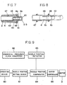
- FIGURE 9 includes a pushbutton or other operating device 60 provided in the vicinity of the part cleaning device, a nozzle position setting device 61 connected to the operating device 60, a commercial frequency clock converter 62. provided in the vicinity of the power source for the motor 3, a nozzle position detector 63 connected to the converter 62 and a nozzle position comparator 64 connected to the devices 62 and 63.
- the anus cleaning position S-1, the functioning position as a bidet S-2 and the self-cleaning position S-3 of the nozzle body 4 are stored in the nozzle position setting device 61 and each compared with the actual position of the nozzle body 4 which is detected by the nozzle position detector 63.
- the power circuit for the motor 3 is connected to the nozzle position comparator 64 through a motor controller 65 which turns on or off the supply of power to the motor 3 in response to the output of the comparator 64.
- the flow chart of FIGURE 10 showing a system for controlling the movement of the nozzle body 4 includes an actual nozzle position timer MT and a set nozzle position timer PT. If the operating device 60 is actuated to turn on the power circuit for the motor 3, its output shaft 11 is rotated to unwind the leaf spring 12 from the drum 10 and move the nozzle body 4 forward to its cleaning position. The number of cycles of the frequency of the power source starts to be counted simultaneously with the turning on of the power circuit. When the nozzle body 4 has reached one of its cleaning positions, the power circuit is turned off to discontinue the rotation of the motor 3 and stop the nozzle body 4 at its designated anus cleaning position S-1 or functioning position as a bidet S-2, as shown in FIGURE 3.
- the motor 3 is a synchronous type and therefore, the nozzle body 4 may be accurately positioned if the frequency of the power source is counted. However, because incorrect positioning is possible, a pair of stop members 70 and 71 are provided in the cylinder 2 to ensure that the nozzle body 4 is stopped at its retracted position S-4 or at its functioning position as a bidet S-2.
- a semiconductor control device may be employed to enable the motor 3 to start when the voltage of the power source is zero. This arrangement eliminates any error in the counting of the number of cycles and improves the accuracy of nozzle positioning control.
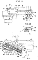
- a frame 72 is secured along one side of the cylinder 2 and has an inner surface on which lead switches 73, 74 and 75 are provided for detecting each position of the nozzle body 4 when it is in its anus cleaning position S-1, functioning position as a bidet S-2, and retracted position S-4, respectively.
- the cylinder 2 is formed on the one side thereof with a recess 76.
- a magnet 77 which faces one of the lead switches 73 to 75 depending on the position of the nozzle body 4 is secured to the nozzle body 4 and exposed through the recess 76. When the magnet 77 has come to one of the lead switches 73 to 75 during the movement of the nozzle body 4, a corresponding signal is transmitted to the control system for the motor 3 to enable the detection of the nozzle position and its accurate positioning.
- FIGURES 13 and 14 Another arrangement for positioning the nozzle body 4 is shown in FIGURES 13 and 14. It employs Hall ICs for detecting the position of the nozzle body 4 in motion instead of the lead switches as mentioned above.
- Such arrangement includes a magnet 80 mounted on the proximal end of the nozzle body 4 in such a way that the directions of both poles thereof may be perpendicular to the direction of axial movement of the nozzle body 4.
- Three Hall ICs H i , H 2 and H 3 are provided for detecting the position of the nozzle body 4 in cooperation with the magnet 80.
- the Hall ICs H 1 to H 3 are mounted on the inner surface of the upper plate 81 of the cylinder 2 in parallel to the nozzle body 4 and in a way forming a perpendicular magnetic field with the magnet 80.
- the first to third Hall ICs H1 to H 1 to H 3 are so situated as to face the magnet 80 when the nozzle body 4 has reached its retracted position S-4, anus cleaning position S-1, and functioning
- the Hall ICs are turned on or off by a magnetic field as is known in the art.
- the Hall ICs H 1 to H 3 are switched on or off when the magnet 80 creates a magnetic field of intensity above a certain level. They produce a low output voltage when switched on, and a high output voltage when switched off.
- FIGURE 15 shows the principle of nozzle position control by the Hall ICs H 1 to H 3 and the magnet 80.
- the system of FIGURE 15 includes a central processing unit (CPU) 82 in a system 83 provided in the part cleaning device A for controlling all of the electrical components thereof, and a solid-state relay 84 for controlling the supply of power to the motor 3, a cleaning water heater, a heater for warming the toi let seat, a heater for the hot air fan H and the electromagnetic valve in the piping.
- the Hall ICs H 1 to H 3 are connected to the CPU 82 by position signal lines 85 to 87, respectively.
- Lead wires 88 and 89 are connected to the upper plate 81 of the cylinder 2 for supplying an electric current to the Hall ICs H, to H 3 .
- the cleaning start switch 53 on the control panel 52 is turned on and the motor 3 is started in response to a signal from the CPU 82 to release the leaf spring 12 from the drum 10, whereby the nozzle body 4 is moved forward. If the nozzle body 4 reaches its anus cleaning position S-1, the second Hall IC H 2 faces the magnet 80 and is turned on at a low output voltage as shown by graph (2) in FIGURE 15. Its output is fed back to the CPU 82 and the CPU 82 determines the Hall IC from which it has received the output signal.
- the CPU 82 transmits a signal to the motor 3 to rotate it in the opposite direction to retract the nozzle body 4 into the cylinder 2.
- the magnet 80 has come to face the first Hall IC H 1 , it produces a low output voltage as shown by graph (1) in FIGURE 15 and in response to the output of the Hall IC H i , the CPU 82 stops the rotation of the motor 3, whereby the nozzle body 4 is held in its retracted position within the cylinder 2.
- the start switch for a bidet 55 is turned on to move the nozzle body 4 to its functioning position as a bidet S-2.
- the magnet 80 cooperates with the third Hall IC H 3 to position the nozzle body 4 in its functioning position as a bidet S-2.
- the stop switch 54 may be depressed to retract the nozzle body 4 into the cylinder 2.
- An additional Hall IC or ICs may be employed to provide an additional cleaning position or positions.
- the use of Hall ICs is convenient for enabling the detection of the nozzle body in a plurality of cleaning positions.
- the Hall ICs which do not have any contact, are easier to handle, assemble and mount than the lead switches.
- the use of lead switches 10 or Hall ICs does not present any problem in the position control of the nozzle body 4, since the leaf spring 12 on the precision cylindrical surface of the drum 10 converts the rotation of the output shaft 11 of the motor 3 accurately to the axial movement of the nozzle body 4.
Landscapes
- Engineering & Computer Science (AREA)
- Health & Medical Sciences (AREA)
- Public Health (AREA)
- Hydrology & Water Resources (AREA)
- Life Sciences & Earth Sciences (AREA)
- Epidemiology (AREA)
- Molecular Biology (AREA)
- Water Supply & Treatment (AREA)
- Human Computer Interaction (AREA)
- Manufacturing & Machinery (AREA)
- Physics & Mathematics (AREA)
- General Physics & Mathematics (AREA)
- Automation & Control Theory (AREA)
- Bidet-Like Cleaning Device And Other Flush Toilet Accessories (AREA)
Description
- This invention relates to a device for moving a nozzle in a spray cleaning device for washing the anus and functioning as a bidet. The term "spray cleaning device" as herein used means an apparatus including a tank for cleaning water, a cleaning nozzle which is movable between its retracted position and its cleaning position, a system for heating the cleaning water, a system for supplying the heated cleaning water, a system for moving the nozzle and devices for controlling those systems, and provided at the rear end of a water closet for directing a jet of heated cleaning water toward the private parts through the nozzle in its cleaning position.
- In the spray cleaning device, it is usually the case that the nozzle has two cleaning positions, i.e., the position for cleaning the anus and the position for functioning as a bidet.
- There are known two arrangements for moving the nozzle forward from its retracted position to its cleaning positions and backward.
- One of them relies on the pressure of cleaning water for moving the nozzle forward. The nozzle is slidably disposed in a cylinder and the cleaning water is introduced into the cylinder to push the nozzle out of the cylinder to either of its cleaning positions. A spring is connected to the nozzle for urging the nozzle back to its retracted position in the cylinder.
- The other arrangement employs a motor which is rotatable in either direction for moving the nozzle out of, or into, a cylinder. This arrangement will hereunder be described with reference to FIGURE 16.
- The
cylinder 101 is secured in acasing 100 located adjacent to the rear end of a toilet stool (not shown). Thenozzle 102, which comprises a tubular body, is axially slidable in thecylinder 101. Theelectric motor 103 is provided adjacent to the proximal end of thecylinder 101 for moving thenozzle 102 forward or backward. Themotor 103 has an output shaft 104to which acylindrical drum 105 is secured. Aleaf spring 106 has one end wound on, and fastened to, the outer cylindrical surface of thedrum 105. The other end of thespring 106 is connected to the proximal end of thenozzle 102. Theoutput shaft 104 of themotor 103 is rotatable in two directions and the manner of the rotations of theoutput shaft 104 causes the reciprocal motion of thenozzle 102 in thecylinder 101. When thenozzle 102 is brought to its cleaning position, it directs a jet of cleaning water toward the private parts of a person using the toilet through itsend openings 107. The positioning of theconventional nozzle 102 structure is effected by a feedback control system including a sensor of, for example, the magnetic or optical type which is located in a position for monitoring the motion of thenozzle 102. The sensor detects the amount of motion of thenozzle 102 and transmits a corresponding signal to themotor 103 to turn the power circuit of themotor 103 on or off. - The system relying on the pressure of the cleaning water for positioning the nozzle has the disadvantage that if the water pressure is lower than a predetermined level, the nozzle fails to reach its designated cleaning position and accomplish its proper cleaning function. If the nozzle is of thetype having two cleaning positionsforthe anus and for the use as a bidet, respectively, its internal water passages formed in the
nozzle 102 itself are complicated and the size of thenozzle 102 is undesirably enlarged. - The system employing the
motor 103 for moving thenozzle 102 and the sensor for detecting and positioning it has the disadvantage that its nozzle positioning accuracy depends on the performance of the sensor. If the sensor fails to function accurately, thenozzle 102 fails to reach its designated cleaning position and also to accomplish its proper cleaning operation as mentioned above. - The sensor requires a complicated job of assembly including wiring connection between the
motor 103 and the control system and mounting in a predetermined narrow space, and the control system also becomes complicated. Thedrum 105 has, as shown in FIGURE 17, formed on its outer cylindrical surface ashoulder 108 and threadedholes 110 provided in the vicinity of theshoulder 108 for receivingscrews 109 for securing theleaf spring 106. Thus, the outer cylindrical surface of thedrum 105 on which theleaf spring 106 is wound does not have a uniform curvature. As the .drum 105 is rotated alternately in the opposite directions, theleaf spring 106 is wound on the surface of thedrum 105 and unwound therefrom repeatedly. Insofar as the surface of thedrum 105 does not have a uniform curvature, with the passage of time the fatigue of theleaf spring 106 is not uniform along its length, and this causes stress concentration or buckling in theleaf spring 106 which leads to failure in driving thenozzle 102. The fastening of theleaf spring 106 to thedrum 105 by thescrews 109 adds to the amount of labor required for the fabrication of the apparatus and hence the cost thereof. - Another problem that the conventional part cleaning device involves is due to the fact that the distal end portion of the
nozzle 102 which is provided with theopenings 107 projects from thecylinder 101 even when thenozzle 102 is in its retracted position. The projecting distal end portion of thenozzle 102 is always liable to contamination by dirty liquid or matter, whether thenozzle 102 may be in its cleaning or retracted position. The dirty liquid and matter are likely to form powder on the projecting end portion of thenozzle 102 and in itsopenings 107 and thereby to block theopenings 107. They have an objectionable odour, and contaminate cleaning water. - EP-A-0,074,883 relates to a mechanism for rectilinear translation of a slidable body comprising two pulleys and two driving beltswherein each belt with one end is fixed to a pulley and with the other end is fixed to the slidable body. The belts are driven by an electric motor.
- It is an object of this invention to improve a spray cleaning device which includes a drum secured to the output shaft of an electric motor and a leaf spring, so that the connection of the spring to the drum may be simplified, and so that the smooth and proper function of the spring may always be ensured.
- It is another object of this invention to enable the self-cleaning of the exposed distal end portion of the nozzle in a part cleaning device and at the same time the cleaning of the head of its extensible nozzle member both before and after its use to keep it always clean.
- The first object is attained by an improved device for driving a slidable nozzle in a spray cleaning device which comprises a cylinder, a nozzle having at a distal end thereof openings through which cleaning water is directed outwardly, an electric motor for moving the nozzle axially in either direction in the cylinder, a drum secured to the output shaft of the motor and a leaf spring connecting the drum and the nozzle, and characterized in that the drum comprises a main body portion having a sectoral recess and a sectoral insert portion fitted in the sectoral recess and having an arcuate outer peripheral surface defining precision cylindrical drum surface with the outer peripheral surface of the main body portion, and that one end of the leaf spring is secured between the mutually fitting surfaces of the main body and sectoral insert portions.
- As the drum surface is precision round, the amount of the spring which is wound or unwound reflects the amount and angle of the rotation of the output shaft of the motor correctly, and the amount and angle of the rotation of the output shaft are transmitted to the nozzle highly accurately.
- The second object is attained by a device including a nozzle having a flattened nozzle head and adapted for its complete retraction into a cylinder, a first packing member provided in the cylinder for sealing the peripheral surface of the nozzle when it is in its retracted position, a second packing member provided between the first packing member and the distal end of the cylinder and surrounding the nozzle head portion, and a cleaning water feed line connected to the cylinder between the first and second packing members, the nozzle head being temporarily stopped in a position projecting out of the distal end portion of the cylinder immediately before its arrival at its cleaning position and immediately after its departure therefrom so that the cleaning water may be discharged through an annular passage between the second packing member and the nozzle head portion for cleaning the distal end portion of the cylinder and the nozzle head.
- Switches for starting the cleaning operation of the anus and the function as a bidet are provided in a control panel for a part cleaning device. If either of those switches is turned on, the nozzle is temporarily stopped in a position suitable for the 'self-cleaning of the nozzle head. The efec- tromagnetic valve or pump disposed in the cleaning water feed line works for a brief period of time to supply water from a hot water storage tank to the annular passage so that it may clean the nozzle head and the distal end of portion the cylinder before it is discharged into a toilet. Then, if the stop switch provided in the control panel is turned on, the nozzle starts retracting into the cylinder and stops temporarily at its self-cleaning position on its way again. The electromagnetic valve or pump works briefly and water is supplied from the hot water storage tank to the annular passage for cleaning the nozzle head itself and the distal end portion of the cylinder before the nozzle is moved to its completely retracted position in the cylinder.
- FIGURE 1 is a perspective view of a water closet provided with a part cleaning device embodying this invention;
- FIGURE 2 is a schematic top plan view showing the interior of the device shown in FIGURE 1;
- FIGURE 3 is a sectional view taken along the line I-I of FIGURE 2 and showing the longitudinal section of a nozzle device in a retracted position;
- FIGURE 4 is a top plan view, partly in section, of the nozzle device;
- FIGURE 5 is an exploded perspective view of a drum and a leaf spring;
- FIGURE 6 is a perspective view showing the proximal end of the leaf spring secured to the drum;
- FIGURE 7 is a fragmentary longitudinal sectional view of the nozzle in its self-cleaning position;
- FIGURE 8 is a perspective view showing a nozzle distal end and a first and a second packing members;
- FIGURE 9 is a block diagram showing a control circuit for an electric motor;
- FIGURE 10 is a flow chart showing the operation of the motor;
- FIGURE 11 is a top plan view, partly in section, of the nozzle device of which the positioning is effected by lead switches and a magnet;
- FIGURE 12 is a sectional view taken along the line II-II of FIGURE 11;
- FIGURE 13 is a longitudinal sectional view of the nozzle device of which the positioning is effected by Hall ICs and a magnet;
- FIGURE 14 is a top plan view, partly in section, of the nozzle device shown in FIGURE 13;
- FIGURE 15 shows the principle of nozzle position detection by a magnet and Hall ICs;
- FIGURE 16 is a longitudinal sectional view of a conventional nozzle device; and
- FIGURE 17 is a perspective view of a conventional drum for driving the nozzle.
- A water closet provided with a part cleaning device A embodying this invention is shown in FIGURE 1 and comprises a toilet stool B, a flushing water tank C, a lavatory seat D and a lid E. The part cleaning device A comprises a
base 1, a tank F for heating and storing cleaning water, a valve unit G for supplying the cleaning water, a hot air fan H for drying after cleaning and a nozzle device N located approximately in the center of the device and connected to the tank F by a cleaning water supply pipe P. The nozzle device N comprises acylinder 2 secured on thebase 1 and having a base end to which anelectric motor 3 is integrally mounted, and atubular nozzle body 4 provided axially movably in thecylinder 2, as shown in FIGURES 3 and 4. Themotor 3 is a synchronous motor having an output shaft adapted for rotation synchronously with the frequency of a power source. - The
cylinder 2 is provided at the distal end thereof with anelbow 5 for connection to the cleaning water supply pipe P. When thenozzle body 4 has been moved forward to its cleaning position, theelbow 5 communicates with a water passage formed in thenozzle body 4 so that a jet of cleaning water may be directed outwardly through a plurality of first andsecond end openings - A
cylindrical drum 10 is secured to the output shaft 11 of themotor 3. Athin leaf spring 12 has its proximal end fastened to thedrum 10 and the distal end of theleaf spring 12 is connected to the proximal end portion of thenozzle body 4. Thedrum 10 is formed from a synthetic resin. It comprises amain body portion 15 and aninsert portion 16 for securing theleaf spring 12 integrally to themain body portion 15, as shown in FIGURE 5. Themain body portion 15 has acentral boss 17 secured about the output shaft 11, and a major arc-shaped cylindrical outer peripheral orrim surface 18 formed with asectoral recess 19. Therecess 19 defines a pair ofradial walls rim surface 18. Thewall 20 has agroove 22 and thewall 21 also has agroove 23. Both of thegrooves drum 10. Thegroove 23 has apositioning projection 24 approximately at the middle thereof. - The
insert portion 16 has a sectoral cross section and can be fitted in thesectoral recess 19. Theinsert portion 16 has an arcuate outer peripheral orrim surface 25 and a pair ofradial walls rim surface 25 has a radius of curvature which is equal to that of therim surface 18 of themain body portion 15, and the rim surfaces 18 and 25 form a precision cylindrical surface when theinsert portion 16 is fitted in themain body portion 15. Thewall 26 is formed on its outer surface with a pair ofprojections 28 for engaging theleaf spring 12, as shown in FIGURE 6. Thewall 27 is provided at its radially inner edge with an outwardly directedflange 29 having approximately at the middle thereof arecess 30 in which thepositioning projection 24 can be received. - The
leaf spring 12 is so bent prior to assembly as to closely fit thewall 26 of theinsert portion 16 and the rim surfaces 18 and 25, and has thebent end portion 31 formed with a pair ofholes 32 for receiving theprojections 28 on thewall 26, as shown in FIGURE 6. - The
projections 28 extending through theholes 32 are fitted in thegroove 22 of thewall 20 and theflange 29 is fitted in thegroove 23 of thewall 21, as is obvious from FIGURE 5. The other end of theleaf spring 12 is connected by apin 33 to the proximal end portion of thenozzle body 4, as shown in FIGURE 3. - If the output shaft 11 of the
motor 3 is rotated in one direction, theleaf spring 12 is unwound from the rim surfaces 18 and 25 of thedrum 10 to enable thenozzle body 4 to move forward to its cleaning position, and if the output shaft 11 of themotor 3 is rotated in the reverse direction, theleaf spring 12 is wound on the drum to enable thenozzle body 4 to return to its retracted position. Insofar as thedrum 10 has a precision cylindrical surface defined by the rim surfaces 18 and 25, theleaf spring 12 is subjected to uniform compression or tensile stress along its entire length when it is being either wound or unwound around thedrum 10. Theleaf spring 12 always works smoothly without being subjected to any localization of stress concentration or buckling, and therefore has long life and good durability. Theleaf spring 12 is easy to be secured to thedrum 10, as it is sufficient to fit theinsert portion 16 in themain body portion 15. - The
nozzle body 4 is of the double-walled construction and comprises anouter tube 40 and aninner tube 41 disposed in theouter tube 40 coaxially therewith. Therefore, thenozzle body 4 has afirst water passage 44 defined between the outer andinner tubes nozzle head 43 at the outer end of theouter tube 40, and asecond water passage 45 extending through theinner tube 41 and leading to thenozzle head 43. Thenozzle head 43 is provided at its top with three or fivefirst jet openings 6a andsecond jet openings 6b, though the number of those openings may have to be selected to provide the force of water required for cleaning the anus or the function for a bidet. Thenozzle head 43 is flattened on the top and the bottom by a pair ofshoulders 46 dividing it from the rest of thenozzle body 4. - The
cylinder 2 is provided inwardly of its outer distal end portion with afirst packing member 47 and asecond packing member 48 both having a Y-shaped cross section and surrounding thenozzle head 43 therebetween when thenozzle body 4 is in its completely retracted position. The packingmembers shoulders 46 on thenozzle head 43 define anannular passage 49 in thecylinder 2. Theannular passage 49 is connected to thepassage 51 in theelbow 5 which is connected to the cleaning water supply pipe P leading to the tank F. Theouter tube 40 has first and second water inlet openings (not shown) through which theannular passage 49 is connected to the first andsecond water passages nozzle body 4 when it is in its cleaning position. - The nozzle device N including the
nozzle body 4 is secured to thebase 1 in a casing W in such a way that thenozzle body 4 may be axially movable into the bowl B-1 of the toilet stool B. The jetting of the cleaning water from the nozzle device N is started by a cleaningstart switch 53 and a start switch for abidet 55 provided on acontrol panel 52 and stopped by astop switch 54 also provided on thecontrol panel 52. - The
nozzle body 4 can be stopped at three cleaning positions, i.e., the anus cleaning position S-1, the position for functioning as a bidet S-2 and self-cleaning position S-3. When thenozzle body 4 is in its first stop position S-1 by the operation of the cleaningstart switch 53, cleaning water flows from theannular passage 49 to thefirst jet openings 6a through the first inlet opening (not shown) and thefirst water passage 44 for cleaning the anus. When thenozzle body 4 is in its second stop position S-2 by the operation of the start switch for abidet 55, water flows from theannular passage 49 to thesecond jet openings 6b through the second inlet opening (not shown) and thesecond water passage 45 for the use as a bidet. The supply of cleaning water from the tank F may be effected by a known device, i.e., by an electromagnetic valve in the valve unit G if water is supplied directly, or by an electromagnetic pump (not shown) if it is supplied indirectly. - According to a salient feature of this invention, the electromagnetic valve or pump is in operation for a brief period of time immediately after the
nozzle body 4 has been temporarily stopped at its self-cleaning position S―3, and immediately after it has been retracted toward thecylinder 2 and stopped temporarily at its self-cleaning position S-3 again. This is a very short period of, say, one to several seconds required for cleaning thenozzle head 43 and the adjacent end of thecylinder 2. - If the
nozzle body 4 stops at its self-cleaning position S-3, thenozzle head 43 is displaced outwardly relative to thepacking members cylinder 2, as shown in FIGURE 7. Thesecond packing member 48 leaves theshoulders 46 on thenozzle head 43. Theannular passage 49 communicates to the atmosphere through the annular opening between thesecond packing member 48 and thenozzle head 43 and water is discharged at a reduced pressure for cleaning thenozzle head 43 and the adjacent end of thecylinder 2 to keep them clean both before and after the toilet is used. As the pressure of the discharged water for self-cleaning is reduced, water flows along thenozzle head 43 and the adjacent end of thecylinder 2 slowly and does not undesirably jet out from theannular passage 49 into the bowl B-1 or splash out of the water closet B. - The
nozzle body 4 does not necessarily need to be of the type having two water supply routes for cleaning the anus and for the use as a bidet, respectively, as hereinabove described. The first andsecond packing members annular passage 49 in thecylinder 2 do not necessarily need to have a Y-shaped cross section, but may have another cross sectional shape, for example, a U-shaped cross section. - A method of controlling the position of the
nozzle body 4 will now be described with reference to FIGURE 9. The block diagram of FIGURE 9 includes a pushbutton orother operating device 60 provided in the vicinity of the part cleaning device, a nozzleposition setting device 61 connected to the operatingdevice 60, a commercialfrequency clock converter 62. provided in the vicinity of the power source for themotor 3, anozzle position detector 63 connected to theconverter 62 and anozzle position comparator 64 connected to thedevices nozzle body 4 are stored in the nozzleposition setting device 61 and each compared with the actual position of thenozzle body 4 which is detected by thenozzle position detector 63. The power circuit for themotor 3 is connected to thenozzle position comparator 64 through amotor controller 65 which turns on or off the supply of power to themotor 3 in response to the output of thecomparator 64. - The flow chart of FIGURE 10 showing a system for controlling the movement of the
nozzle body 4 includes an actual nozzle position timer MT and a set nozzle position timer PT. If the operatingdevice 60 is actuated to turn on the power circuit for themotor 3, its output shaft 11 is rotated to unwind theleaf spring 12 from thedrum 10 and move thenozzle body 4 forward to its cleaning position. The number of cycles of the frequency of the power source starts to be counted simultaneously with the turning on of the power circuit. When thenozzle body 4 has reached one of its cleaning positions, the power circuit is turned off to discontinue the rotation of themotor 3 and stop thenozzle body 4 at its designated anus cleaning position S-1 or functioning position as a bidet S-2, as shown in FIGURE 3. - When the
nozzle body 4 is moved back to its retracted position S―4 in thecylinder 2, themotor 3 is kept in operation for several more cycles even after the counted number of cycles indicating the actual position of thenozzle body 4 has coincided with a set value representing its retracted position S-4. This ensures the return of thenozzle body 4 to its completely retracted position S-4 and eliminates its inaccurate positioning which might otherwise result from the repeated operation of themotor 3. A similar control system is used for positioning thenozzle body 4 relative to its self-cleaning position S―3. - The
motor 3 is a synchronous type and therefore, thenozzle body 4 may be accurately positioned if the frequency of the power source is counted. However, because incorrect positioning is possible, a pair ofstop members cylinder 2 to ensure that thenozzle body 4 is stopped at its retracted position S-4 or at its functioning position as a bidet S-2. - if required, a semiconductor control device may be employed to enable the
motor 3 to start when the voltage of the power source is zero. This arrangement eliminates any error in the counting of the number of cycles and improves the accuracy of nozzle positioning control. - The use of the precision.
cylindrical drum 10 and theleaf spring 12 for converting the rotation of themotor 3 to the axial reciprocating movement of thenozzle body 4 enables the accurate conversion of the amount and angle of rotation of the output shaft 11 to the amount of movement of thenozzle body 4. This feature permits the use of a nozzle position sensor for the accurate positioning of thenozzle body 4 as shown in FIGURE 11. - Referring to FIGURE 11, a
frame 72 is secured along one side of thecylinder 2 and has an inner surface on which lead switches 73, 74 and 75 are provided for detecting each position of thenozzle body 4 when it is in its anus cleaning position S-1, functioning position as a bidet S-2, and retracted position S-4, respectively. Thecylinder 2 is formed on the one side thereof with arecess 76. Amagnet 77 which faces one of the lead switches 73 to 75 depending on the position of thenozzle body 4 is secured to thenozzle body 4 and exposed through therecess 76. When themagnet 77 has come to one of the lead switches 73 to 75 during the movement of thenozzle body 4, a corresponding signal is transmitted to the control system for themotor 3 to enable the detection of the nozzle position and its accurate positioning. - Another arrangement for positioning the
nozzle body 4 is shown in FIGURES 13 and 14. It employs Hall ICs for detecting the position of thenozzle body 4 in motion instead of the lead switches as mentioned above. Such arrangement includes amagnet 80 mounted on the proximal end of thenozzle body 4 in such a way that the directions of both poles thereof may be perpendicular to the direction of axial movement of thenozzle body 4. Three Hall ICs Hi, H2 and H3 are provided for detecting the position of thenozzle body 4 in cooperation with themagnet 80. The Hall ICs H1 to H3 are mounted on the inner surface of theupper plate 81 of thecylinder 2 in parallel to thenozzle body 4 and in a way forming a perpendicular magnetic field with themagnet 80. The first to third Hall ICs H1 to H1 to H3 are so situated as to face themagnet 80 when thenozzle body 4 has reached its retracted position S-4, anus cleaning position S-1, and functioning position as a bidet S-2, respectively. - The Hall ICs are turned on or off by a magnetic field as is known in the art. The Hall ICs H1 to H3 are switched on or off when the
magnet 80 creates a magnetic field of intensity above a certain level. They produce a low output voltage when switched on, and a high output voltage when switched off. - FIGURE 15 shows the principle of nozzle position control by the Hall ICs H1 to H3 and the
magnet 80. The system of FIGURE 15 includes a central processing unit (CPU) 82 in asystem 83 provided in the part cleaning device A for controlling all of the electrical components thereof, and a solid-state relay 84 for controlling the supply of power to themotor 3, a cleaning water heater, a heater for warming the toi let seat, a heater for the hot air fan H and the electromagnetic valve in the piping. The Hall ICs H1 to H3 are connected to theCPU 82 by position signal lines 85 to 87, respectively. Leadwires upper plate 81 of thecylinder 2 for supplying an electric current to the Hall ICs H, to H3. - In order to move the
nozzle body 4 forward from its retracted position S-4 as shown in FIGURE 13 to its anus cleaning position S-1, the cleaningstart switch 53 on thecontrol panel 52 is turned on and themotor 3 is started in response to a signal from theCPU 82 to release theleaf spring 12 from thedrum 10, whereby thenozzle body 4 is moved forward. If thenozzle body 4 reaches its anus cleaning position S-1, the second Hall IC H2 faces themagnet 80 and is turned on at a low output voltage as shown by graph (2) in FIGURE 15. Its output is fed back to theCPU 82 and theCPU 82 determines the Hall IC from which it has received the output signal. If it determines the signal as having been received from the second Hall IC H2, it discontinues the supply of power to themotor 3. Thenozzle body 4 is held at its anus cleaning position S-1 and the electromagnetic valve, or the like is opened to jet out cleaning water. If the anus has been cleaned, thestop switch 54 is operated. TheCPU 82 transmits a signal to themotor 3 to rotate it in the opposite direction to retract thenozzle body 4 into thecylinder 2. When themagnet 80 has come to face the first Hall IC H1, it produces a low output voltage as shown by graph (1) in FIGURE 15 and in response to the output of the Hall IC Hi, theCPU 82 stops the rotation of themotor 3, whereby thenozzle body 4 is held in its retracted position within thecylinder 2. - The start switch for a
bidet 55 is turned on to move thenozzle body 4 to its functioning position as a bidet S-2. Themagnet 80 cooperates with the third Hall IC H3 to position thenozzle body 4 in its functioning position as a bidet S-2. Thestop switch 54 may be depressed to retract thenozzle body 4 into thecylinder 2. - An additional Hall IC or ICs may be employed to provide an additional cleaning position or positions. The use of Hall ICs is convenient for enabling the detection of the nozzle body in a plurality of cleaning positions. Moreover, the Hall ICs, which do not have any contact, are easier to handle, assemble and mount than the lead switches.
- According to this invention, the use of lead switches 10 or Hall ICs does not present any problem in the position control of the
nozzle body 4, since theleaf spring 12 on the precision cylindrical surface of thedrum 10 converts the rotation of the output shaft 11 of themotor 3 accurately to the axial movement of thenozzle body 4. - In addition to the various advantages of this invention as hereinabove set forth, it is also useful to remove cold water from the cleaning water supply pipe and wet the first and
second packing members nozzle body 4 and prolong the life of thepacking members
Claims (3)
Applications Claiming Priority (6)
| Application Number | Priority Date | Filing Date | Title |
|---|---|---|---|
| JP4181785U JPH0338301Y2 (en) | 1985-03-23 | 1985-03-23 | |
| JP41817/84U | 1985-03-23 | ||
| JP67885/84 | 1985-03-31 | ||
| JP60067885A JPS61229038A (en) | 1985-03-31 | 1985-03-31 | Front and rear cleaning equipment |
| JP67886/84 | 1985-03-31 | ||
| JP6788685A JPS61229039A (en) | 1985-03-31 | 1985-03-31 | sanitary cleaning equipment |
Related Child Applications (2)
| Application Number | Title | Priority Date | Filing Date |
|---|---|---|---|
| EP89200604.0 Division-Into | 1985-06-04 | ||
| EP89200604A Division EP0330291B1 (en) | 1985-03-23 | 1985-06-04 | A method of controlling the position of a slidable body |
Publications (3)
| Publication Number | Publication Date |
|---|---|
| EP0195842A2 EP0195842A2 (en) | 1986-10-01 |
| EP0195842A3 EP0195842A3 (en) | 1987-08-26 |
| EP0195842B1 true EP0195842B1 (en) | 1990-01-10 |
Family
ID=27290960
Family Applications (1)
| Application Number | Title | Priority Date | Filing Date |
|---|---|---|---|
| EP85106922A Expired EP0195842B1 (en) | 1985-03-23 | 1985-06-04 | Spray cleaning device |
Country Status (3)
| Country | Link |
|---|---|
| US (1) | US4628548A (en) |
| EP (1) | EP0195842B1 (en) |
| DE (2) | DE3575321D1 (en) |
Families Citing this family (49)
| Publication number | Priority date | Publication date | Assignee | Title |
|---|---|---|---|---|
| FR2614448B1 (en) * | 1987-04-23 | 1989-07-13 | Logilift Sarl | METHOD FOR REGULATING THE ROTATION SPEED OF AN ELECTRIC MOTOR, MEANS EMPLOYING THIS METHOD AND MOTORS PROVIDED WITH SUCH MEANS |
| US4903347A (en) * | 1987-05-20 | 1990-02-27 | Garcia Gilbert C | Automated cleansing apparatus adaptable to a commode |
| FR2627916B1 (en) * | 1988-02-25 | 1990-08-17 | Jaeger | DIRECT CURRENT MOTOR CONTROL DEVICE |
| US4987617A (en) * | 1989-03-16 | 1991-01-29 | Aisin Seiki Kabushiki Kaisha | Nozzle mechanism in a sanitary device |
| ATE128203T1 (en) * | 1989-09-18 | 1995-10-15 | Geberit Ag | INSTALLATION BLOCK FOR A WATER TOILET. |
| JP2516190Y2 (en) * | 1990-06-18 | 1996-11-06 | アイシン精機株式会社 | Human body cleaning device |
| KR940000125B1 (en) * | 1990-12-14 | 1994-01-07 | 삼성전자 주식회사 | Blower device of human local washer |
| USD355246S (en) | 1992-05-01 | 1995-02-07 | Toto Ltd. | Combined bidet, bidet control, toilet seat and cover |
| AU1590895A (en) * | 1994-02-10 | 1995-08-29 | Toto Ltd. | Toilet attachment with easily detachable seat |
| EP0819798A4 (en) * | 1995-02-28 | 1999-02-24 | Toto Ltd | Seat device |
| DE69628000T2 (en) * | 1995-02-28 | 2004-05-19 | Toto Ltd., Kita-Kyushu | HYGIENIC CLEANER |
| US5630234A (en) * | 1995-08-28 | 1997-05-20 | Childs; Jack D. | Bidet assembly |
| US5813060A (en) * | 1996-09-12 | 1998-09-29 | Klopocinski; Stanislaw | Multifunction toilet |
| US6073275A (en) * | 1996-09-12 | 2000-06-13 | Klopocinski; Stanislaw | Multifunction toilet |
| US5864895A (en) * | 1997-03-10 | 1999-02-02 | Toto Ltd | Handy body washer |
| US6470513B1 (en) * | 1998-06-01 | 2002-10-29 | Estle A. Cook | Easy rise hygienic toilet lift |
| WO2001092653A1 (en) * | 2000-06-01 | 2001-12-06 | Inax Corporation | Western-style water closet |
| CH694468A5 (en) * | 2000-09-13 | 2005-01-31 | Geberit Balena Ag | Water closet. |
| US20110209774A1 (en) * | 2003-01-24 | 2011-09-01 | American Biffy Company, Ltd. | Bidet device self cleaning nozzle |
| US7284285B2 (en) * | 2005-02-01 | 2007-10-23 | Saverio Scalzi | Toilet and bidet system |
| US7428758B2 (en) * | 2005-08-17 | 2008-09-30 | Hyug Park | Coin operating bidet response to user's selection |
| TW200738941A (en) * | 2006-02-10 | 2007-10-16 | Toto Ltd | Sanitary washing toilet seat device, and toilet device |
| EP2067901B2 (en) * | 2007-12-05 | 2018-07-25 | Geberit International AG | Device with a flushing device and a WC body, installation set for installation of such a device and method for installing the device |
| CN101634164A (en) * | 2008-07-23 | 2010-01-27 | 德昌电机(深圳)有限公司 | Closestool nozzle transmission structure |
| US9049970B2 (en) | 2010-06-25 | 2015-06-09 | Maximo Dorra | Auto cleaning toilet seat with anal cleaning device and blow dry |
| US8776278B1 (en) | 2013-04-16 | 2014-07-15 | Maximo Dorra | Auto cleaning toilet seat and drying system |
| US8060953B1 (en) | 2010-06-25 | 2011-11-22 | Auto Cleaning Toilet Seat, L.L.C. | Auto cleaning toilet seat with anal cleaning device and blow dry |
| US8365317B1 (en) | 2010-06-25 | 2013-02-05 | Maximo Dorra | Auto cleaning toilet seat with anal cleaning device and blow dry |
| US9044533B2 (en) * | 2010-12-09 | 2015-06-02 | Jiangmen Idear Hanyu Electrical Joint-Stock Co., Ltd. | Method for emptying rectum |
| CN102518195B (en) * | 2011-11-15 | 2014-06-04 | 上海科勒电子科技有限公司 | Driving device for spraying pipe and spraying pipe with same |
| CN102518197B (en) * | 2011-12-15 | 2013-12-25 | 上海科勒电子科技有限公司 | Spray tube device |
| CN102885594B (en) * | 2012-09-05 | 2015-04-29 | 王湘冀 | Toilet lid with flushing function |
| KR20150024779A (en) * | 2013-08-26 | 2015-03-09 | 코웨이 주식회사 | Nozzle assembly for bidet |
| CN105637155B (en) * | 2013-10-08 | 2017-08-11 | 松下知识产权经营株式会社 | Clean washing apparatus |
| WO2017193111A1 (en) | 2016-05-06 | 2017-11-09 | Whole Bath, Llc | A seat and cover system with dynamic spray nozzle |
| US10982422B2 (en) | 2016-08-11 | 2021-04-20 | Whole Bath, Llc | Wash system with a cleanser assembly |
| CA3060680A1 (en) | 2016-05-06 | 2017-11-09 | Whole Bath, Llc | A medicine delivery, wash, clean and air dry system |
| US10563390B2 (en) | 2017-12-19 | 2020-02-18 | Whole Bath, Llc | Wash and clean apparatus |
| CA3061046C (en) | 2016-05-06 | 2023-01-03 | Whole Bath, Llc | Seat and cover system with medical units |
| US10869583B2 (en) | 2016-07-16 | 2020-12-22 | Whole Bath, Llc | Wash, clean and dry system with removable spray canister device |
| US11253114B2 (en) | 2016-05-06 | 2022-02-22 | Whole Bath, Llc | Wash, clean and dry system with removable spray canister device |
| US11458260B2 (en) | 2016-07-16 | 2022-10-04 | Bemis Manufacturing Company | Spray canister device with removable sleeved cover |
| WO2017193112A1 (en) | 2016-05-06 | 2017-11-09 | Whole Bath, Llc | Dynamic drying mechanism for a wash and clean system |
| US12172178B2 (en) * | 2018-09-06 | 2024-12-24 | Universal City Studios Llc | Telescopic fountain nozzle with discrete extension and water activation |
| US11242192B2 (en) | 2019-05-30 | 2022-02-08 | Whole Bath, Llc | Spray canister device |
| US11739516B2 (en) | 2019-07-15 | 2023-08-29 | Bemis Manufacturing Company | Toilet seat assembly |
| US11445869B2 (en) | 2019-07-15 | 2022-09-20 | Bemis Manufacturing Company | Toilet seat assembly |
| KR102695508B1 (en) * | 2022-11-04 | 2024-08-14 | (주) 아이젠 | Nozzle drive device for bidet |
| US11913212B2 (en) * | 2023-09-29 | 2024-02-27 | Xiamen Shengborui Technology Co., Ltd. | Bidet folding structure |
Family Cites Families (13)
| Publication number | Priority date | Publication date | Assignee | Title |
|---|---|---|---|---|
| US1935201A (en) * | 1933-01-27 | 1933-11-14 | Callejo Modesto | Lavatory fixture |
| US2104271A (en) * | 1937-06-23 | 1938-01-04 | Parisini Primo | Spraying device for evacuation |
| US3575729A (en) * | 1969-08-21 | 1971-04-20 | Blue Haven Pools Inc | Automatically extensible and retractable suction and scouring action pool cleaner |
| DE2646021C3 (en) * | 1976-10-12 | 1979-05-23 | Hans Zollikerberg Zuerich Maurer (Schweiz) | Under-shower for toilets |
| DE2826059C3 (en) * | 1977-06-17 | 1981-06-25 | Aisin Seiki K.K., Kariya, Aichi | Shower device |
| JPS5937860Y2 (en) * | 1979-12-17 | 1984-10-20 | 日産自動車株式会社 | Dial type wire control device |
| US4438662A (en) * | 1981-04-02 | 1984-03-27 | Walton Eric K | Automatic control system having manual control engageable at will |
| FR2512909B1 (en) * | 1981-09-15 | 1987-02-20 | Renault | RECTILINEAR PULLEY AND BELT TRANSMISSION MECHANISM |
| US4449260A (en) * | 1982-09-01 | 1984-05-22 | Whitaker Brackston T | Swimming pool cleaning method and apparatus |
| DE3410590A1 (en) * | 1982-10-06 | 1985-01-10 | Aisin Seiki K.K., Kariya, Aichi | Washing device for body parts |
| JPS5965138A (en) * | 1982-10-06 | 1984-04-13 | アイシン精機株式会社 | Apparatus for cleaning puvic of human body |
| WO1984001973A1 (en) * | 1982-11-09 | 1984-05-24 | Matsushita Electric Industrial Co Ltd | Sanitary washing apparatus |
| US4564961A (en) * | 1983-03-29 | 1986-01-21 | Aisin Seiki Co., Ltd. | Appliance for washing parts of human body |
-
1985
- 1985-05-31 US US06/740,127 patent/US4628548A/en not_active Expired - Lifetime
- 1985-06-04 DE DE8585106922T patent/DE3575321D1/en not_active Expired - Fee Related
- 1985-06-04 EP EP85106922A patent/EP0195842B1/en not_active Expired
- 1985-06-04 DE DE8989200604T patent/DE3583946D1/en not_active Expired - Fee Related
Also Published As
| Publication number | Publication date |
|---|---|
| DE3583946D1 (en) | 1991-10-02 |
| EP0195842A3 (en) | 1987-08-26 |
| DE3575321D1 (en) | 1990-02-15 |
| EP0195842A2 (en) | 1986-10-01 |
| US4628548A (en) | 1986-12-16 |
Similar Documents
| Publication | Publication Date | Title |
|---|---|---|
| US4628548A (en) | Device and method of moving and controlling the position of a slidable body such as used for body cleansing | |
| CN1890510B (en) | Heat exchanger and cleaning device with same | |
| KR101104428B1 (en) | Sanitary washing device | |
| US3278974A (en) | Shampooing device including foam generating mechanism | |
| JPH0811983B2 (en) | Flow control system | |
| JPS63503232A (en) | automatic flow control device | |
| EP0330291B1 (en) | A method of controlling the position of a slidable body | |
| US4616368A (en) | Sanitary cleaning apparatus | |
| CN109881766A (en) | A floor drain with low energy consumption and easy to clean | |
| EP0167099A2 (en) | Sanitary cleaning apparatus | |
| CN107227777B (en) | Sterilizing water spray device and body wash equipped with the same | |
| KR900004247B1 (en) | Nozzle driving device of sanitary washing device and nozzle position control method in the nozzle driving device | |
| JP2005146554A (en) | Toilet equipment | |
| KR100909724B1 (en) | Bidet flushing device and method | |
| JP2010203162A (en) | Water leakage detector for warm water washing toilet seat | |
| JP3087471B2 (en) | Water spouting device | |
| JP5253231B2 (en) | Hot water toilet seat | |
| JPH0311487Y2 (en) | ||
| JPH0211500Y2 (en) | ||
| JPH0338301Y2 (en) | ||
| JPH0324698Y2 (en) | ||
| JPH11249393A (en) | Corona generator cleaning mechanism | |
| KR970005517Y1 (en) | Bidet | |
| JPH0311488Y2 (en) | ||
| JP3453835B2 (en) | Electric vacuum cleaner |
Legal Events
| Date | Code | Title | Description |
|---|---|---|---|
| PUAI | Public reference made under article 153(3) epc to a published international application that has entered the european phase |
Free format text: ORIGINAL CODE: 0009012 |
|
| AK | Designated contracting states |
Kind code of ref document: A2 Designated state(s): DE FR GB IT NL |
|
| PUAL | Search report despatched |
Free format text: ORIGINAL CODE: 0009013 |
|
| AK | Designated contracting states |
Kind code of ref document: A3 Designated state(s): DE FR GB IT NL |
|
| 17P | Request for examination filed |
Effective date: 19870914 |
|
| 17Q | First examination report despatched |
Effective date: 19881020 |
|
| GRAA | (expected) grant |
Free format text: ORIGINAL CODE: 0009210 |
|
| AK | Designated contracting states |
Kind code of ref document: B1 Designated state(s): DE FR GB IT NL |
|
| XX | Miscellaneous (additional remarks) |
Free format text: TEILANMELDUNG 89200604.0 EINGEREICHT AM 04/06/85. |
|
| ITF | It: translation for a ep patent filed | ||
| REF | Corresponds to: |
Ref document number: 3575321 Country of ref document: DE Date of ref document: 19900215 |
|
| ET | Fr: translation filed | ||
| PLBE | No opposition filed within time limit |
Free format text: ORIGINAL CODE: 0009261 |
|
| STAA | Information on the status of an ep patent application or granted ep patent |
Free format text: STATUS: NO OPPOSITION FILED WITHIN TIME LIMIT |
|
| 26N | No opposition filed | ||
| ITTA | It: last paid annual fee | ||
| PGFP | Annual fee paid to national office [announced via postgrant information from national office to epo] |
Ref country code: NL Payment date: 19930630 Year of fee payment: 9 |
|
| PG25 | Lapsed in a contracting state [announced via postgrant information from national office to epo] |
Ref country code: NL Effective date: 19950101 |
|
| NLV4 | Nl: lapsed or anulled due to non-payment of the annual fee | ||
| PGFP | Annual fee paid to national office [announced via postgrant information from national office to epo] |
Ref country code: GB Payment date: 19970603 Year of fee payment: 13 |
|
| PG25 | Lapsed in a contracting state [announced via postgrant information from national office to epo] |
Ref country code: GB Free format text: LAPSE BECAUSE OF NON-PAYMENT OF DUE FEES Effective date: 19980604 |
|
| GBPC | Gb: european patent ceased through non-payment of renewal fee |
Effective date: 19980604 |
|
| PGFP | Annual fee paid to national office [announced via postgrant information from national office to epo] |
Ref country code: DE Payment date: 20010528 Year of fee payment: 17 |
|
| PGFP | Annual fee paid to national office [announced via postgrant information from national office to epo] |
Ref country code: FR Payment date: 20010611 Year of fee payment: 17 |
|
| PG25 | Lapsed in a contracting state [announced via postgrant information from national office to epo] |
Ref country code: DE Free format text: LAPSE BECAUSE OF NON-PAYMENT OF DUE FEES Effective date: 20030101 |
|
| PG25 | Lapsed in a contracting state [announced via postgrant information from national office to epo] |
Ref country code: FR Free format text: LAPSE BECAUSE OF NON-PAYMENT OF DUE FEES Effective date: 20030228 |
|
| REG | Reference to a national code |
Ref country code: FR Ref legal event code: ST |