EP0195807B1 - Headbox system for a paper machine - Google Patents
Headbox system for a paper machine Download PDFInfo
- Publication number
- EP0195807B1 EP0195807B1 EP85904806A EP85904806A EP0195807B1 EP 0195807 B1 EP0195807 B1 EP 0195807B1 EP 85904806 A EP85904806 A EP 85904806A EP 85904806 A EP85904806 A EP 85904806A EP 0195807 B1 EP0195807 B1 EP 0195807B1
- Authority
- EP
- European Patent Office
- Prior art keywords
- width
- guide device
- distribution box
- headbox
- branch pipes
- Prior art date
- Legal status (The legal status is an assumption and is not a legal conclusion. Google has not performed a legal analysis and makes no representation as to the accuracy of the status listed.)
- Expired
Links
Images


Classifications
-
- D—TEXTILES; PAPER
- D21—PAPER-MAKING; PRODUCTION OF CELLULOSE
- D21F—PAPER-MAKING MACHINES; METHODS OF PRODUCING PAPER THEREON
- D21F1/00—Wet end of machines for making continuous webs of paper
- D21F1/02—Head boxes of Fourdrinier machines
- D21F1/022—Means for injecting material into flow within the headbox
-
- D—TEXTILES; PAPER
- D21—PAPER-MAKING; PRODUCTION OF CELLULOSE
- D21F—PAPER-MAKING MACHINES; METHODS OF PRODUCING PAPER THEREON
- D21F1/00—Wet end of machines for making continuous webs of paper
- D21F1/02—Head boxes of Fourdrinier machines
-
- D—TEXTILES; PAPER
- D21—PAPER-MAKING; PRODUCTION OF CELLULOSE
- D21F—PAPER-MAKING MACHINES; METHODS OF PRODUCING PAPER THEREON
- D21F1/00—Wet end of machines for making continuous webs of paper
- D21F1/02—Head boxes of Fourdrinier machines
- D21F1/024—Details of the feed chamber
-
- D—TEXTILES; PAPER
- D21—PAPER-MAKING; PRODUCTION OF CELLULOSE
- D21F—PAPER-MAKING MACHINES; METHODS OF PRODUCING PAPER THEREON
- D21F1/00—Wet end of machines for making continuous webs of paper
- D21F1/02—Head boxes of Fourdrinier machines
- D21F1/026—Details of the turbulence section
-
- D—TEXTILES; PAPER
- D21—PAPER-MAKING; PRODUCTION OF CELLULOSE
- D21F—PAPER-MAKING MACHINES; METHODS OF PRODUCING PAPER THEREON
- D21F1/00—Wet end of machines for making continuous webs of paper
- D21F1/02—Head boxes of Fourdrinier machines
- D21F1/028—Details of the nozzle section
-
- D—TEXTILES; PAPER
- D21—PAPER-MAKING; PRODUCTION OF CELLULOSE
- D21F—PAPER-MAKING MACHINES; METHODS OF PRODUCING PAPER THEREON
- D21F1/00—Wet end of machines for making continuous webs of paper
- D21F1/06—Regulating pulp flow
Definitions
- the invention relates to a headbox device for a paper machine with a distribution box for distributing a stock suspension fed over the web width of the paper machine, a guide device for the stock suspension having a plurality of holes or channels and a subsequent nozzle space with an adjustable outlet gap for distributing the stock suspension over the Web width of the paper machine, the mass distribution over the web width of the paper machine being adjustable to a predetermined basis weight over the width of the paper machine and for which purpose branches and a collecting container for the adjustable removal of the stock suspension and optionally branches for the adjustable feeding of the suspension in the distribution box are provided on the distribution box.
- Headbox devices of this type are known, for example, from US Pat. No. 4,087,321. They are used to feed a prepared pulp suspension to a paper machine and to distribute it over its entire web width in a certain way. This distribution of the stock suspension should take place in such a way that the paper web produced with the paper machine has certain properties across the web width, whereby usually an even basis weight (mass per unit area) after drying, an even moisture content, and an even fiber orientation over the entire web width are aimed for .
- DE-A-2151 906 it is proposed to achieve a uniform speed and quantity of material also in the edge area by providing a gap that can be individually adjusted over the width on the distributor. Differences in pressure and cross flows in the outlet gap are also present here.
- a device shows the inflow of additional liquid into a high-consistency headbox.
- additional fibrous material is fed through a slot located at the bottom across the entire width.
- German design step DE-AS 11 65 397 it is described how the air which separates at the top of the perforated roller headbox can also be discharged in a controlled manner.
- the invention sets itself the task of eliminating the aforementioned disadvantages of the prior art and, in particular, of creating a headbox device for a paper machine with which, despite the change in the local mass flow rate necessary to set the desired transverse profiles of the basis weight, a flow state in the nozzle chamber and reached at the outlet gap, which is free of cross flows.
- a paper web produced in this way should have a uniform fiber orientation across the web width.
- the headbox device shown in Figure 1 has a distribution box 1, the cross section of which decreases in the direction of flow F of the stock suspension.
- the substance suspension is e.g. to understand a mixture of fibers with additives for paper or cardboard manufacture, but also filler suspensions for paper coating.
- a connecting pipe 2 is connected for supplying the stock suspension, and at the other, opposite end with the smaller cross section, a return line 3.
- the distributor preferably has an approximately conical shape or can be designed as a truncated pyramid.
- a guide device 5 is connected to a longitudinal side 4 of the distributor 1.
- this can be designed as any guiding device customary in paper machine technology, for example, as shown in detail in the figure, as a step diffuser with step-widening parallel channels 6, e.g. according to CH 518406 (US 3725197).
- a nozzle chamber 29 with an outlet gap 8 This being formed by two lips 7 or by a lip and a diaphragm mounted on the lip but freely movable relative to it.
- the stock suspension now passes through the channels 6, the nozzle chamber 29 and the outlet gap 8 to the wire section of the paper machine.
- At least one of the lips 7 or an orifice attached to it is provided with a plurality of adjustment devices 30 distributed over the width, with which the gap width can be adjusted individually over the width manually or by means of a regulating device in order to flow with the material suspension flow rate flowing out of the gap 8 Set the desired oven-dry basis weight profile of the paper web thus produced over the width.
- the gap width is changed locally via adjusting devices 30 at the outlet gap 8
- the local flow conditions such as pressure and Ge, also change in addition to the local mass flow and the basis weight profile speed in the nozzle area.
- the result of the pressure differences are cross flows in the nozzle space, which are present up to the outlet gap 8 and act on the fiber storage on the sieve of the paper machine until the entire fiber structure is fixed in the sheet.
- Pressure compensation can be carried out individually or in combination with various measures.
- One possibility for pressure compensation over the web width of the machine is that, as shown in FIG. 1, on a longitudinal side of the distribution box 1, distributed over its length, a plurality of branches formed as branch lines 11, 12, 13 and 14 are connected to the inside of distributor 1 are connected.
- controllable valves 15, 16, 17, 18, 19 are provided, by means of which the flow of the branch lines and the return line can be changed.
- the branch lines 11, 12, 13 and 14 and the return line 3 are e.g. connected to a common manifold 20.
- the material suspension branched off at the individual connection points of the branch lines and via the return line can be discharged via this.
- the hydrostatic pressure profile in the distributor 1 changes from the location of the connection of the relevant branch lines.
- the extent of the change in pressure can be adjusted by means of the valves 15, 16, 17, 18 and 19, so that by actuating these valves it is possible to set the required pressure curve over the length of the distributor or the width of the paper machine.
- the shape of the distributor 1 can initially roughly predefine a specific pressure profile in the distributor, so that only the remaining deviations need to be corrected by actuating the valves.
- the pressure setting at the various setting points can either be done manually, by means of a visual pressure indicator or after observing the paper web generated or according to the measurement results for certain paper properties, which were determined with suitable sensors across the width of the paper web, e.g. the basis weight, or the fiber orientation, or, as indicated in FIG. 1, with the aid of a control device 26 connected to the various measuring devices.
- pressure measuring devices 21, 22, 23, 24 and 25 are provided along the flow direction F on the distributor 1, with which the hydrostatic pressure of the suspension in the distributor 1 or its course in the longitudinal direction is determined.
- such pressure measuring devices can be designed and arranged as desired, wherein the pressure measurement can also take place in the nozzle area.
- the measuring devices can be assigned to the individual valves and control them directly, or the measuring devices can supply their measured values to the control device 26 independently of the valves, which controls and adjusts the individual valves in a suitable manner, for example by means of a process computer, until as long as the desired pressure prevails at all measuring points.
- the pressure profile specified by the control device 26 can be selected so that the pressure shows a desired course, for example is kept constant over the entire width, or certain edge corrections can be included, for example a somewhat higher pressure at both edges, to prevent pressure losses to compensate for the side walls.
- the control device 26 can also be controlled by further sensors, not shown, which, for example, determine or measure the thickness, the basis weight, the curl (curl) or the fiber orientation of the paper produced along the width of the paper web and deliver corresponding additional control signals 28 by means of an additional pressure correction can be carried out or a pressure profile can be specified. If suitable operating personnel are available, such a control can also be carried out in a simpler manner manually or semi-automatically by observing the measured values of the individual measuring devices and adjusting accordingly.
- the cross section of the branch lines 11, 12, 13 and 14 can be different, depending on the necessary correction. Likewise, the mutual distance between these branch lines can be selected differently. However, it is also readily possible to provide lines of the same diameter at the same distance from one another, in a number that ensures the necessary controllability.
- the branch lines can also be used to supply additional stock suspension.
- a feed line is to be provided instead of a return line 20.
- This can be connected to the supply line 2, which is present anyway, or else to a supply line separate therefrom, the devices for flow control 15, 16, 17, 18, 19 being designed as suitable, controllable pumps. If necessary, however, only a part of the branches can be used to remove stock suspension, while the other branches can supply stock suspension.
- the control members can be designed so that the flow direction and the flow rate can be controlled.
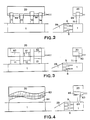
- FIG. 2 shows a variant in two vertical sections, in which the distribution box 1 is connected to a collecting container 20 via connecting lines 11-14.
- the height of the end of the connecting lines 11, 12, 13, 14, which goes into the collecting container 20, is adjustable, for example by sleeves 66 which can be displaced from the outside or by a telescopic design of the connecting lines which extends over at least part of the connecting lines. This creates a weir that is adjustable in height and thus makes the local pressure in the distributor individually adjustable.
- Figure 3 shows a modification in which the connecting lines 11, 12, 13 are designed as slots with underlying, adjustable surface elements 60, 61 and 62, which serve as overflow weirs. By adjusting these surface elements, the effective weir height can be changed locally, so that a local pressure correction in the distribution box 1 also takes place here.
- FIG. 4 Another possibility for influencing the pressure conditions is shown in FIG. 4, in which material is not drawn off via individual branch lines arranged across the machine width, but via an outlet slot 64 between distribution box 1 and collecting container 20, the outlet slot 64 covering the entire machine width goes.
- a vertical overflow weir 63 extending over the entire width is also provided in the collecting container 20, the height of which can be adjusted locally over the width from the outside.
- a change in the hydrostatic pressure in the distributor or in the nozzle can thereby be achieved simply by changing the weir height of the outlet slot 64.
- a displaceable screen 65 can also be provided, by means of which the outlet slot 64 can be individually adjusted over the width.
- branch lines or connecting slots can also be provided at other points of the headbox device, for example on the diffuser block 5, or in the nozzle chamber 29 immediately after the diffuser block or just before the outlet gap 8 or in between.
- FIG. 5 shows an analog headbox device in vertical section, in which a distributor 1, a diffuser 5 with a row of parallel channels 6, and a nozzle chamber 29 with an outlet gap 8 are again provided.
- the stock suspension flows from the nozzle chamber 29 onto the screen 32 of a paper machine which is guided over a breast roller 31.
- the front part 33 of the upper delimitation lip 7 of the nozzle chamber 29 can be individually adjusted over the width by means of a joint 34 and by adjusting device 35 distributed over the width of the outlet gap 8.
- the exit gap is delimited at the top by a diaphragm which is mounted on the upper lip, but is freely movable to a certain extent in relation to the upper lip. The gap width can then be changed using the adjustment devices attached to the panel.
- the amount of suspension emerging from the gap can be controlled locally independently over the width.
- the supply or discharge of fibrous suspension again takes place via branch lines 11 on the distributor 1 and also or optionally via branch lines 51 on the nozzle chamber 29, valves or pumps 36 or the designs shown in FIGS. 2-4 being provided for quantity regulation.
- branch lines are provided either selectively or in combination on the distributor 1, on the diffuser block 5 or on the nozzle chamber 29. Changes in the pressure curve can be compensated for as close as possible to the point of origin.
- the possibility is provided to provide branch lines 37 on the upper side of the distributor 1 or at another location. Instead, the branch lines can also be led directly out of the diffuser block 5.
- lines 39 are in the first diffuser stage, lines 40 into the second diffuser stage immediately after the paragraph to the first stage, or lines 41 into the third diffuser stage immediately after the paragraph to the second stage.
- supply lines can also be provided in the nozzle space 29 itself, for example lines 42 in the beginning of the nozzle space, directly behind the outlet openings 43 from the diffuser channels or lines 44, which are in the vicinity of the outlet gap 8 of the nozzle space 29 in the movable part 33 of the upper part Lippe flows out.
- these lines can be used to add or remove water or white water with a lower consistency or suspension, depending on the requirements for the purpose of pressure control or to change the consistency.
- Another possibility of regulating the pressure in the distributor 1 can be created by changing the distributor cross-section, e.g. through a movably designed rear wall 45 of the distributor.
- the mobility can be achieved in that the rear wall 45 can be adjusted either manually or by means of a control device over the width of the distribution box, as a result of which the pressure profile in the distributor can be set, or in that the rear wall 45 is designed as a flexible and deformable membrane which is automatic , for example with the help of a pressure pad on the back so that the same pressure prevails over the entire width of the distribution box.
- adjustment options 52 are necessary, which are to be provided immediately after the guide device, in front of the outlet gap or also in between, wherein the adjustment devices can also be attached at two and more positions in the machine direction.
- adjustable screens 46 in front of the inlet openings 38 of the diffuser channels 6 or corresponding adjustable screens 47 in front of the outlet openings 43 of the diffuser channels.
- adjustable screens 46 can consist of sliding elements, iris diaphragms, inflatable bodies or other elements.
- Suspension or water can also be supplied via lines 50 directly at the inlet 38 of the channels, or the channels can be narrowed by controllable pressure bodies 27.
- the increased pressure loss at the edges e.g. due to friction on the side walls 9 can be compensated for by changing the pressure loss of the guide device in the edge zones, e.g. is reduced, which is achieved by changing the passage cross section per unit width.
- FIG. 7 shows an example of a diffuser block 5 with a plurality of rows of stacked diffusers arranged one above the other.
- the cross section of the diffusers in the edge zone 48 on the side wall 9 is larger than in the adjoining central zone 49, so that the pressure loss in the stock suspension in the edge zone is somewhat smaller than in the middle and thus the increased Pressure losses in the peripheral zone can be compensated.
- the individual rows of step diffusers are offset from one another, which means that a lower nozzle pressure is created in the edge zone 48 due to the diffusers missing relative to the center 49.
- a larger material flow per unit of width is achieved in the edge zone by making additional bores or by reducing the pressure loss of the individual element of the guide device in the edge area, so that a pressure correction is also possible here.
- fundamental defects in the distribution board design or at another location on the paper machine can also be compensated for by changing and adapting the hole diameter or pressure loss across the web width.
- the branch lines 11 connected to the collecting line 20 can advantageously also be connected at the highest point of the distributor 1, which ensures that any air excretions can be safely removed.
- the connection for the diffuser 5 can be provided, so that the pressure control takes place in the immediate vicinity of the inlet of the diffuser.
- the collecting line can also be guided directly along the distributor 1, so that the branches 11 are formed by openings which connect the distributor 1 and the collecting line 20.
- FIG. 10 shows an example in which the diffuser is designed as a guide device which is known per se and which connects a distributor 1 with the lips 7 and an outlet gap 8 and which has two pipe systems 53 and which are connected in series and are separated by a space 55 bypassing the suspension 54 has.
- This intermediate space 55 is connected through branch openings 56 with an independently controllable or adjustable cross section to an overflow line 57, which at the same time shows a damping effect.
- FIG. 11 shows an analogous example in which controllability is achieved by means of slide 58. that change the cross section of the branch openings.
- the openings 59 can optionally also be brought forward to the beginning of the nozzle chamber 29.
Abstract
Description
Die Erfindung betrifft eine Stoffauflauf-Vorrichtung für eine Papiermaschine mit einem Verteilerkasten zur Verteilung einer zugeführten Stoffsuspension über die Bahnbreite der Papiermaschine, einer eine Vielzahl von Löchern oder Kanälen aufweisenden Führungsvorrichtung für die Stoffsuspension und einem anschliessenden Düsenraum mit einem einstellbaren Auslaufspalt zur Verteilung der Stoffsuspension über die Bahnbreite der Papiermaschine, wobei die Massenverteilung über die Bahnbreite der Papiermaschine auf ein vorgegebenes Flächengewicht über die Breite der Papiermaschine einstellbar ist und wozu am Verteilerkasten Abzweigungen und ein Sammelbehälter zum einstellbaren Abführen der Stoffsuspension und gegebenenfalls Abzweigungen zum einstellbaren Zuführen der Suspension in den Verteilerkasten vorgesehen sind.The invention relates to a headbox device for a paper machine with a distribution box for distributing a stock suspension fed over the web width of the paper machine, a guide device for the stock suspension having a plurality of holes or channels and a subsequent nozzle space with an adjustable outlet gap for distributing the stock suspension over the Web width of the paper machine, the mass distribution over the web width of the paper machine being adjustable to a predetermined basis weight over the width of the paper machine and for which purpose branches and a collecting container for the adjustable removal of the stock suspension and optionally branches for the adjustable feeding of the suspension in the distribution box are provided on the distribution box.
Solche Stoffauflauf-Vorrichtungen sind beispielsweise aus der US-4 087 321 bekannt. Sie dienen dazu, eine vorbereitete Faserstoff-Suspension einer Papiermaschine zuzuführen und über deren gesamte Bahnbreite in bestimmter Weise zu verteilen. Diese Verteilung der Stoffsuspension soll derart erfolgen, dass die mit der Papiermaschine erzeugte Papierbahn bestimmte Eigenschaften über die Bahnbreite hat, wobei meist ein gleichmässiges Flächengewicht (Masse pro Flächeneinheit) nach der Trocknung, eine gleichmässige Feuchte, sowie eine gleichmässige Faserorientierung über die gesamte Bahnbreite angestrebt wird.Headbox devices of this type are known, for example, from US Pat. No. 4,087,321. They are used to feed a prepared pulp suspension to a paper machine and to distribute it over its entire web width in a certain way. This distribution of the stock suspension should take place in such a way that the paper web produced with the paper machine has certain properties across the web width, whereby usually an even basis weight (mass per unit area) after drying, an even moisture content, and an even fiber orientation over the entire web width are aimed for .
Aus der US-3 556 935 oder US-4 089 739 ist es dazu bekannt, die Weite des Auslaufspaltes des Düsenraumes mittels mehrerer, über die Bahnbreite verteilter Einstelleinrichtungen verstellbar auszubilden. Hiermit lässt sich zwar die Stoffsuspensionsmenge über die Bahnbreite steuern, jedoch nicht die Faserorientierung.It is known from US Pat. No. 3,556,935 or US Pat. No. 4,089,739 to make the width of the outlet gap of the nozzle space adjustable by means of a plurality of adjusting devices distributed over the web width. This allows you to control the amount of material suspension over the web width, but not the fiber orientation.
Unzulänglichkeiten, die im Aufbau der Papiermaschine liegen, sowie physikalische Vorgänge während des Papierherstellungsprozesses sind der Grund dafür, dass meist nicht alle gewünschten Eigenschaften über die Bahnbreite gleichzeitig wie gewünscht oder gleichmässig sind. Beispielsweise werden Mängel in der Siebpartie oder das Schrumpfen der Papierbahn während der Trocknung, insbesondere am Bahnrand, durch Aenderung des lokalen Stoffmengenstromes ebenso ausgeglichen, wie Unzulänglichkeiten in der Geometrie des Verteilers, der Führungsvorrichtung oder des Düsenraumes. Zur Änderung oder Einstellung eines bestimmten lokalen Stoffmengenstromes wird vielfach die Weite des Austrittsspaltes aus dem Düsenraum lokal verändert. Dadurch wird jedoch auch der Druck im Düsenraum örtlich verändert und der Druckverlauf in der Faserstoff-Suspension über die Maschinenbreite ungleichmässig. Diese örtlichen Druckunterschiede im Düsenraum führen zu Querströmungen im Düsenraum, die sich bis hin zum Auslaufspalt auswirken, und zwar in der Weise, dass die Richtung der Strömung im Düsenraum, über die Breite gesehen, nicht exakt parallel und mit der Maschinenrichtung übereinstimmend ist. Selbst kleine Abweichungen von der Maschinenrichtung führen wegen der beim Austritt des Suspensionsstrahles vorhandenen Querkomponenten des Geschwindigkeitsvektors zu unerwünschten Ungleichmässigkeiten der Faserorientierung der erzeugten Papierbahn über die Bahnbreite.Inadequacies that lie in the construction of the paper machine, as well as physical processes during the paper production process, are the reason why not all of the desired properties across the web width are usually at the same time as desired or even. For example, defects in the wire section or the shrinking of the paper web during drying, especially at the web edge, are compensated for by changes in the local mass flow, as are deficiencies in the geometry of the distributor, the guide device or the nozzle area. In order to change or set a specific local mass flow, the width of the outlet gap from the nozzle space is often changed locally. However, this also changes the pressure in the nozzle area locally and the pressure curve in the fiber suspension is uneven across the machine width. These local pressure differences in the nozzle space lead to cross-flows in the nozzle space, which have an effect right up to the outlet gap, in such a way that the direction of the flow in the nozzle space, seen across the width, is not exactly parallel and corresponds to the machine direction. Even small deviations from the machine direction lead to undesired nonuniformities in the fiber orientation of the paper web produced across the web width because of the transverse components of the speed vector which exist when the suspension jet emerges.
Aus AT-363 776 ist es bereits bekannt, Druckunterschiede in der strömenden Stoffsuspension im Verteiler dadurch über die Bahnbreite auszugleichen, dass der Stoffsuspension an geeigneten Stellen, beispielsweise im Verteilerkasten zusätzlich Stoffsuspension zugeführt, oder abgezogen wird, so dass der Druckverlauf im Verteilkasten über die gesamte Bahnbreite konstant ist. Allein mit dieser Massnahme können jedoch nicht sämtliche Druckunterschiede im Düsenraum ausgeglichen werden.From AT-363 776 it is already known to compensate for pressure differences in the flowing stock suspension in the distributor over the web width by adding or subtracting stock suspension at suitable points, for example in the distribution box, so that the pressure curve in the distribution box over the entire Web width is constant. However, this measure alone cannot compensate for all pressure differences in the nozzle area.
Aus der US-3 573 160 ist es bekannt, das Geschwindigkeitsprofil der Stoffsuspension über die Bahnbreite zu messen und den Querschnitt des Verteilers, z.B. mittels einer verstellbaren Wand, entsprechend einzustellen, um eine gleichmässige Geschwindigkeit der Suspension im Auslaufspalt zu erreichen. Es ist weiterhin aus der Europaischen Patentanmeldung EP-A 0 029 905 eine ähnliche Lösung zur Beeinflussung des Druckprofils im Verteiler entnehmbar, bei der die Form der Verteilerrückwand veränderbar ist. Auch durch diese Lösungen können Druckunterschiede und Querströmungen nur unvollkommen verhindert werden.From US-3,573,160 it is known to measure the speed profile of the stock suspension over the web width and the cross-section of the distributor, e.g. by means of an adjustable wall to adjust accordingly in order to achieve a uniform speed of the suspension in the outlet gap. From the European patent application EP-
Wie in der G B-1 216 114 beschrieben, ist auch schon versucht worden, einen gleichmässigen Stofffluss durch mehrere, einzeln einstellbare Überlaufrohre am Verteilkasten zu erreichen, womit die genannten Nachteile ebenfalls nicht vermieden werden können.As described in G B-1 216 114, attempts have already been made to achieve a uniform flow of material by means of several individually adjustable overflow pipes on the distribution box, whereby the disadvantages mentioned cannot be avoided either.
Beispielsweise treten im Düsenraum an den Rändern infolge von Reibungsverlusten an den Seitenwänden zusätzliche Druckverluste auf. welche bewirken, dass der Druck im Düsenraum und der durchgesetzte Stoffmengenstrom zum Rand hin abfallen. Auch hierdurch treten im Dusenraum Querströmungen auf, die zur Folge haben, dass die Stromfäden nicht mehr exakt parallel in Maschinenrichtung ausgerichtet sind.For example, additional pressure losses occur in the nozzle area at the edges due to friction losses on the side walls. which cause the pressure in the nozzle chamber and the flow of material through to the edge to drop. This also causes cross currents in the nozzle area, which means that the current threads are no longer aligned exactly parallel in the machine direction.
In DE-A-2151 906 wird vorgeschlagen, eine gleichmässige Geschwindigkeit und Stoffmenge auch im Randbereich dadurch zu erreichen, dass ein über die Breite individuell einstellbarer Spalt am Verteiler vorgesehen ist. Druckunterschiede und Querströmungen im Auslaufspalt sind jedoch auch hier vorhanden.In DE-A-2151 906 it is proposed to achieve a uniform speed and quantity of material also in the edge area by providing a gap that can be individually adjusted over the width on the distributor. Differences in pressure and cross flows in the outlet gap are also present here.
Auch bei mehreren gegeneinander versetzten Reihen von Bohrungen oder Kanälen in der Fuhrungsvorrichtung, wie z.B. in US-4 137 124 offenbart, sind in den Randbereichen Ungleichmassigkeiten, wie geringere Stoffmengenströme pro Breiteneinheit vorhanden, die ebenfalls zu Druckunterschieden und zu Querströmungen im Dusenraum und am Spalt führen. Durch Zuführung von zusätzlicher Stoffsuspension oder Wasser an den Seiten durch die Seitenwände des Düsenraumes hindurch könnte dies zwar ausgeglichen werden, jedoch bedingt dies einen erheblichen maschinellen und steuerungstechnischen Aufwand.Even in the case of several rows of bores or channels in the guide device which are offset with respect to one another, as disclosed, for example, in US Pat. No. 4,137,124, there are non-uniformities in the edge regions, such as lower material flows per unit of width, which also lead to pressure differences and cross-flows in the du and the gap. This could be compensated for by supplying additional material suspension or water on the sides through the side walls of the nozzle space, but this requires considerable mechanical and control-related expenditure.
Eine Vorrichtung nach US 4 285 767 zeigt die Zuströmung von zusätzlicher Flüssigkeit in einen Hochkonsistenz-Stoffauflauf. In einem anderen, durch US 2 904 461 beschriebenen Lochwalzenstoffauflauf älterer Bauart wird durch einen über die ganze Breite am Boden befindlichen Schlitz zusätzlicher Faserstoff zugeführt.A device according to US 4,285,767 shows the inflow of additional liquid into a high-consistency headbox. In another perforated roller headbox of the older type described by US 2 904 461, additional fibrous material is fed through a slot located at the bottom across the entire width.
Aus der FR 1 519 450 ist es ebenfalls bekannt, im Stoffauflauf gezielt Verdünnungswasser zur lokalen Stoffdichteregelung zuzugeben.From
In der deutschen Auslegeschritt DE-AS 11 65 397 wird beschrieben, wie auch die sich oben im Lochwalzenstoffauflauf absondernde Luft geregelt abgeleitet werden kann.In the German design step DE-AS 11 65 397 it is described how the air which separates at the top of the perforated roller headbox can also be discharged in a controlled manner.
Auch wenn diese Lösungen eine Auswirkung auf die Strömungsrichtung am Austrittsspalt des Stoffauflaufes haben können, so sind diese Anwirkungen jedoch nicht in ausreichendem Masse steuerbar und nicht von den übrigen ebenfalls vorgegebenen zur Erzeugung von Papier wesentlichen Parametern trennbar.Even if these solutions can have an effect on the direction of flow at the outlet gap of the headbox, these effects cannot be controlled to a sufficient extent and cannot be separated from the other parameters that are also essential for the production of paper.
Die Erfindung setzt sich die Aufgabe, die vorstehend genannten Nachteile des Standes der Technik zu beseitigen und insbesondere eine Stoffauflauf-Vorrichtung für eine Papiermaschine zu schaffen, mit der man trotz der zur Einstellung gewünschter Querprofile des Flächengewichts notwendigen Änderung des lokalen Stoffmengenstromes einen Strömungszustand im Düsenraum und am Auslaufspalt erreicht, der frei von Querströmungen ist. Eine auf diese Weise erzeugte Papierbahn soll eine gleichmässige Faserorientierung über die Bahnbreite aufweisen.The invention sets itself the task of eliminating the aforementioned disadvantages of the prior art and, in particular, of creating a headbox device for a paper machine with which, despite the change in the local mass flow rate necessary to set the desired transverse profiles of the basis weight, a flow state in the nozzle chamber and reached at the outlet gap, which is free of cross flows. A paper web produced in this way should have a uniform fiber orientation across the web width.
Mit der erfindungsgemässen Vorrichtung wird diese Aufgabe durch Massnahmen gelöst, die im Kennzeichen des Anspruches 1 ausgegeben sind.With the device according to the invention, this object is achieved by measures which are given in the characterizing part of
Durch diese Einstellmöglichkeiten wird erreicht, dass die Strömung im Auslaufspalt so beeinflusst wird, dass bei einer Einstellung der Massenverteilung auf ein gewünschtes Querprofil trotzdem keine Querströmungen auftreten, und somit ein Papier mit gewünschter Massenverteilung und mit gewünschter, z.B. gleichmässiger Faserverteilung bezüglich Menge und Orientierung über die Bahnbreite erhalten wird. Es ist aber denkbar, dass, wenn es gewünscht wäre, auch andere Strömungsformen in der Stoffauflaufvorrichtung mit den erfindungsgemässen Mitteln einstellbar würden.These setting options ensure that the flow in the outlet gap is influenced in such a way that when the mass distribution is set to a desired cross profile, no cross flows nevertheless occur, and thus a paper with the desired mass distribution and with the desired, e.g. uniform fiber distribution with regard to quantity and orientation over the web width is obtained. However, it is conceivable that, if it were desired, other flow forms in the headbox device could also be set with the means according to the invention.
Die Erfindung sowie vorteilhafte Weiterbildungen derselben werden anhand der in den Figuren dargestellten Ausführungsbeispiele näher erläutert.
Figur 1 zeigt eine Stoffauflauf-Vorrichtung in der Aufsicht,- Figuren 2-4 zeigen verschiedene Ausführungen von Verteilkästen mit einstellbarem Druckverlauf in zwei Vertikalschnitten,
Figur 5 zeigt eine Stoffauflauf-Vorrichtung im Vertikalschnitt,Figur 6 zeigt eine Stoffauflauf-Vorrichtung mit verschiedenen möglichen Zugabe- oder Entnahmestellen für Stoffsuspension oder Zugabestellen für Wasser,Figuren 7 und 8 zeigen Führungsvorrichtungen mit unterschiedlicher Geometrie über die Bahnbreite,- Figuren 9-11 zeigen verschiedene Anordnungen von Zuleitungen und Abzweigungen an einem Stoffauflauf.
- FIG. 1 shows a headbox device in a top view,
- FIGS. 2-4 show different designs of distribution boxes with adjustable pressure profiles in two vertical sections,
- FIG. 5 shows a headbox device in vertical section,
- FIG. 6 shows a headbox device with various possible addition or removal points for stock suspension or addition points for water,
- FIGS. 7 and 8 show guide devices with different geometries over the web width,
- Figures 9-11 show different arrangements of feed lines and branches on a headbox.
Die in Figur 1 dargestellte Stoffauflauf-Vorrichtung weist einen Verteilerkasten 1 auf, dessen Querschnitt sich in Flussrichtung F der Stoffsuspension verkleinert. Als Stoffsuspension ist dabei z.B. eine Mischung von Fasern mit Zusatzstoffen zur Papier- oder Kartonherstellung zu verstehen, jedoch auch Füllstoffsuspensionen zur Papierbeschichtung. Am Ende des Verteilers mit dem grosseren Querschnitt ist ein Anschlussrohr 2 zur Zuführung der Stoffsuspension angeschlossen, und an dessen anderes, entgegengesetztes Ende mit dem kleineren Querschnitt eine Rückführleitung 3. Der Verteiler besitzt vorzugsweise eine annähernd konische Form oder kann als Pyramidenstumpf ausgebildet sein.The headbox device shown in Figure 1 has a
An eine Längsseite 4 des Verteilers 1 ist eine Führungsvorrichtung 5 angeschlossen. Diese kann im Prinzip als beliebige, in der Papiermaschinentechnik übliche Führungsvorrichtung ausgebildet sein, beispielsweise wie in der Figur ausschnittsweise dargestellt, als Stufendiffusor mit sich stufenweise erweiternden parallelen Kanälen 6, z.B. gemäss CH 518406 (US 3725197).A
An den Ausgang dieser Kanäle 6 schliesst sich ein Düsenraum 29 mit Austrittsspalt 8 an, wobei dieser von zwei Lippen 7 gebildet wird oder von einer Lippe und einer an der Lippe montierten, aber gegenüber dieser frei beweglichen Blende. Die Stoffsuspension gelangt nun über die Kanäle 6, den Düsenraum 29 und den Austrittsspalt 8 auf die Siebpartie der Papiermaschine.At the exit of these
Wenigstens eine der Lippen 7 oder eine an ihr angebrachte Blende ist mit mehreren, über die Breite verteilten Verstelleinrichtungen 30 versehen, mit denen die Spaltweite individuell über die Breite manuell oder mittels einer Regeleinrichtung eingestellt werden kann, um mit dem aus dem Spalt 8 ausströmenden Stoffsuspensionsmengenstrom ein gewünschtes ofentrockenes Flächengewichtsprofil der damit erzeugten Papierbahn über die Breite einzustellen. Wenn jedoch die Spaltweite über Verstelleinrichtungen 30 am Austrittsspalt 8 lokal verändert wird, ändern sich neben dem lokalen Stoffmengenstrom und dem Flächengewichtsprofil auch die lokalen Strömungsverhältnisse, wie Druck und Geschwindigkeit im Düsenraum. Die Folge der Druckunterschiede sind Querströmungen im Düsenraum, die bis hin zum Auslaufspalt 8 vorhanden sind und sich am Sieb der Papiermaschine so lange auf die Faserlagerung auswirken, bis der gesamte Faserverband im Blatt fixiert ist. Wegen der über die Bahnbreite der Maschine unterschiedlichen Querströmungen kommt es dann zu einer unterschiedlichen Faserlagerung im Blatt über die Bahnbreite. Um derartige Querströmungen der Stoffsuspension zu verhindern, sind bestimmte Vorkehrungen erforderlich. Eine dieser Möglichkeiten besteht darin, unter Beibehaltung des eingestellten Spaltweitenprofils den Druck der Stoffsuspension über die Bahnbreite der Papiermaschine bzw. die Breite des Düsenraumes nachzustellen oder nachzuregeln.. Andererseits kann jedoch auch die Spaltweite konstant gehalten werden und statt dessen die Stoffdichte örtlich so geändert werden, dass bei konstantem Druck über die Breite das gewünschte Querprofil, z.B. des Ofentrocken-Flächengewichtes in der Papierbahn entsteht. Dazu ist es erforderlich, an geeigneten Stellen individuell über die Breite verteilt, Stoffsuspension oder Wasser zuzugeben oder abzuführen.At least one of the
Ähnlich wie Spaltweitenverstellungen wirkt sich ein anderes Phänomen aus, das dadurch entsteht, dass an den Rändern der Papiermaschine infolge Reibungsverlusten an den Seitenwänden 9 zusätzlich ein Druckverlust in der Stoffsuspension eintritt. Statt diesen Druckverlust durch Zuführung von Suspension oder Wasser durch die Seitenwände 9 hindurch über zusätzliche Leitungen 10 zu kompensieren, was einen erheblichen maschinellen und steuerungstechnischen Aufwand bedeutet, kann die erforderliche Kompensation auf einfachere und präzisere Weise durch die gleiche Druckregelung oder Stoffdichte-Regelung bzw. durch die gleiche Änderung der Geometrie erfolgen, wie sie zur Einhaltung eines bestimmten Flächengewichtsprofiles bei gleichmässiger Faserorientierung erforderlich ist. Auf die gleiche Weise lässt sich weiterhin das beim Trocknen von Papierbahnen an den Rändern auftretende Schrumpfen kompensieren, so dass eine über die gesamte Bahnbreite gleichmässige Papierbahn entsteht.Similar to gap width adjustments, another phenomenon has an effect, which arises from the fact that at the edges of the paper machine, as a result of frictional losses on the
Eine Druckkompensation kann mit verschiedenen Massnahmen einzeln oder in Kombination miteinander erfolgen. Eine Möglichkeit zur Druckkompensation über die Bahnbreite der Maschine besteht darin, dass wie in Figur 1 gezeigt, an einer Längsseite des Verteilerkastens 1 über dessen Länge verteilt mehrere, als Abzweigleitungen 11, 12, 13 und 14 ausgebildete Abzweigungen an geschlossen sind, die mit dem Inneren des Verteilers 1 in Verbindung stehen. In diesen Abzweigleitungen sind steuerbare Ventile 15, 16, 17, 18, 19 vorgesehen, mittels derer der Durchfluss der Abzweigleitungen und der Rückführleitung verändert werden kann. Die Abzweigleitungen 11, 12, 13 und 14 sowie die Rückführleitung 3 sind z.B. an eine gemeinsame Sammelleitung 20 angeschlossen. Über diese kann die an den einzeinen Anschlusspunkten der Abzweigleitungen und über die Rückführleitung abgezweigte Stoffsuspension abgeführt werden. Je nach abgeführter Menge der Suspension in den einzelnen Abzweigleitungen ändert sich der hydrostatische Druckverlauf im Verteiler 1 ab dem Ort des Anschlusses der betreffenden Abzweigleitungen. Durch die Ventile 15, 16, 17, 18 und 19 ist das Mass der Druckveränderung einstellbar, so dass es durch Betätigung dieser Ventile möglich ist, den erforderlichen Druckverlauf über die Länge des Verteilers bzw. die Breite der Papiermaschine einzustellen. Durch die Form des Verteilers 1 kann dabei zunächst ein bestimmter Druckverlauf im Verteiler grob vorgegeben werden, so dass nur noch die verbleibenden Abweichungen durch die Betätigung der Ventile korrigiert werden müssen.Pressure compensation can be carried out individually or in combination with various measures. One possibility for pressure compensation over the web width of the machine is that, as shown in FIG. 1, on a longitudinal side of the
Die Druckeinstellung an den verschiedenen Einstellpunkten kann entweder manuell, mittels visueller Druckanzeiger oder nach Beobachtung der erzeugten Papierbahn bzw. entsprechend den Messergebnissen für bestimmte Papiereigenschaften, die mit geeigneten Sensoren quer über die Breite der Papierbahn ermittelt wurden, z.B. das Flächengewicht, oder die Faserorientierung, vorgenommen werden oder, wie in Figur 1 angedeutet, mit Hilfe einer, an die verschiedenen Messeinrichtungen angeschlossenen Regeleinrichtung 26. Dazu sind entlang der Flussrichtung F am Verteiler 1 Druckmessvorrichtungen 21, 22, 23, 24 und 25 vorgesehen, mit welchen der hydrostatische Druck der Suspension im Verteiler 1 bzw. dessen Verlauf in Längsrichtung bestimmt wird. Solche Druckmesseinrichtungen können im Prinzip beliebig ausgebildet und angeordnet sein, wobei die Druckmessung auch im Düsenraum erfolgen kann. Im einfachsten Fall können die Messvorrichtungen den einzelnen Ventilen zugeordnet sein und diese direkt steuern, oder die Messeinrichtungen können unabhängig von den Ventilen ihre Messwerte der Regeleinrichtung 26 zuführen, die beispielsweise mittels eines Prozessrechners die einzelnen Ventile in geeigneter Weise steuert und nachregelt, so lange bis an allen Messpunkten der gewünschte Druck herrscht.The pressure setting at the various setting points can either be done manually, by means of a visual pressure indicator or after observing the paper web generated or according to the measurement results for certain paper properties, which were determined with suitable sensors across the width of the paper web, e.g. the basis weight, or the fiber orientation, or, as indicated in FIG. 1, with the aid of a
Das durch die Regeleinrichtung 26 vorgegebene Druckprofil kann dabei so gewählt sein, dass der Druck einen gewünschten Verlauf zeigt, z.B. über die gesamte Breite konstant gehalten wird, oder es können gewisse Randkorrekturen eingeschlossen sein, beispielsweise ein etwas hoherer Druck an beiden Rändern, um Druckverluste an den Seitenwänden zu kompensieren. Zusatzlich kann die Regeleinrichtung 26 noch durch weitere, nicht dargestellte Sensoren angesteuert werden, die beispielsweise die Dicke, das Flachengewicht, den Curl (Rollneigung) oder die Faserorientierung des erzeugten Papieres entlang der Breite der Papierbahn feststellen oder messen und entsprechende zusätzliche Steuersignale 28 liefern, mittels derer eine zusätzliche Druckkorrektur durch geführt oder ein Druckprofil vorgegeben werden kann. Falls geeignetes Bedienungspersonal vorhanden ist, kann eine derartige Steuerung jedoch auch auf einfachere Weise manuell oder halbautomatisch durch Beobachtung der Messwerte der einzelnen Messeinrichtungen und entsprechende Nachregelung erfolgen. Häufig ist eine solche einfachere Steuerung ausreichend, da in der Regel eine einmalige Anpassung nach dem Anlaufen einer Papiermaschine genügt und ein Nachregeln lediglich erforderlich wird, wenn sich Betriebsparameter, z.B. der Druck oder die Zusammensetzung der zugeführten Stoffsuspension ändert, bzw. wenn die Produktion geändert wird, z.B. wenn die Maschine auf eine andere Art von Stoffsuspension umgestellt wird, die eine Änderung der Druckverteilung zur Folge hat. Bei vorbekannten Stoffauflauf-Vorrichtungen war dies nur mit Schwierigkeiten und Komplikationen möglich.The pressure profile specified by the
Der Querschnitt der Abzweigleitungen 11, 12, 13 und 14 kann unterschiedlich sein, entsprechend der notwendigen Korrektur. Ebenso kann der gegenseitige Abstand dieser Abzweigleitungen unterschiedlich gewählt sein. Jedoch ist es auch ohne weiteres möglich, Leitungen gleichen Durchmessers im gleichen Abstand voneinander vorzusehen, und zwar in einer Anzahl, die die notwendige Steuerbarkeit gewährleistet.The cross section of the
Statt über die Abzweigleitungen einen Teil der Stoffsuspension abzuführen, können die Abzweigleitungen auch zur Zuführung von zusätzlicher Stoffsuspension dienen. In diesem Fall ist statt einer Rückführleitung 20 eine Zuführleitung vorzusehen. Diese kann an die ohnehin vorhandene Zuführleitung 2 angeschlossen sein, oder auch an eine davon getrennte Zufuhr, wobei die Vorrichtungen zur Durchfluss-Steuerung 15, 16, 17, 18, 19 als geeignete, steuerbare Pumpen ausgebildet sind. Nötigenfalls kann aber auch nur ein Teil der Abzweigungen der Abführung von Stoffsuspension dienen, während die anderen Abzweigungen Stoffsuspension zuführen können. Die Steuerorgane können dabei so ausgebildet sein, dass die Durchflussrichtung und die Durchflussmenge steuerbar sind.Instead of discharging part of the stock suspension via the branch lines, the branch lines can also be used to supply additional stock suspension. In this case, a feed line is to be provided instead of a
Figur 2 zeigt eine Variante in zwei Vertikalschnitten, bei der der Verteilerkasten 1 über Verbindungsleitungen 11-14 mit einem Sammelbehälter 20 verbunden ist. Das Ende der Verbindungsleitungen 11, 12, 13, 14, das in den Sammelbehälter 20 geht, ist in der Höhe verstellbar ausgebildet, beispielsweise durch von aussen verschiebbare Hülsen 66 oder durch wenigstens über einen Teil der Verbindungsleitungen gehende teleskopartige Ausführung der Verbindungsleitungen. Damit wird ein in der Höhe verstellbares Wehr geschaffen und somit der lokale Druck im Verteiler individuell einstellbar gemacht.FIG. 2 shows a variant in two vertical sections, in which the
Figur 3 zeigt eine Abwandlung, bei der die Verbindungsleitungen 11, 12, 13 als Schlitze ausgebildet sind mit dahinterliegenden, verstellbaren Flächenelementen 60, 61 und 62, die als Überlaufwehre dienen. Durch Verstellung dieser Flächenelemente kann die wirksame Wehrhöhe lokal verändert werden, so dass auch hier eine lokale Druckkorrektur im Verteilerkasten 1 erfolgt.Figure 3 shows a modification in which the connecting
Eine andere Möglichkeit, die Druckverhältnisse zu beeinflussen, ist in Figur 4 dargestellt, bei der ein Stoffabzug nicht über einzelne, über die Maschinenbreite angeordnete Abzweigleitungen erfolgt, sondern über einen Auslaufschlitz 64 zwischen Verteilerkasten 1 und Sammelbehälter 20, wobei der Auslaufschlitz 64 über die gesamte Maschinenbreite geht. Im Sammelbehälter 20 ist weiterhin ein über die gesamte Breite gehendes vertikales Überlaufwehr 63 vorgesehen, dessen Höhe von aussen lokal über die Breite einstellbar ist. Dadurch lässt sich eine Änderung des hydrostatischen Drucks im Verteiler oder in der Düse einfach durch eine Veränderung der Wehrhöhe des Auslaufschlitzes 64 erreichen. Statt eines senkrechten Wehres kann auch eine verschiebbare Blende 65 vorgesehen sein, mittels der der Auslaufschlitz 64 über die Breite individuell einstellbar ist.Another possibility for influencing the pressure conditions is shown in FIG. 4, in which material is not drawn off via individual branch lines arranged across the machine width, but via an
Statt die Abzweigleitungen oder Verbindungsschlitze an der Seite des Verteilerkastens 1 anzubringen, können diese jedoch auch an anderen Punkten der Stoffauflauf-Vorrichtung vorgesehen sein, beispielsweise am Diffusorblock 5, oder im Düsenraum 29 unmittelbar nach dem Diffusorblock oder kurz vor dem Auslaufspalt 8 oder auch dazwischen.Instead of attaching the branch lines or connecting slots to the side of the
Figur 5 zeigt eine analoge Stoffauflauf-Vorrichtung im Vertikalschnitt, bei der wiederum ein Verteiler 1, ein Diffusor 5 mit einer Reihe von parallelen Kanälen 6, und ein Düsenraum 29 mit einem Austrittsspalt 8 vorgesehen sind. Die Stoffsuspension fliesst aus dem Düsenraum 29 auf das über eine Brustwalze 31 geführte Sieb 32 einer Papiermaschine. Der Vorderteil 33 der oberen Begrenzungslippe 7 des Düsenraumes 29 ist mittels eines Gelenkes 34 und durch über die Breite des Austrittsspaltes 8 verteilte Verstelleinrichtung 35 über die Breite individuell einstellbar. Vielfach wird der Austrittsspalt oben von einer Blende begrenzt, die auf der oberen Lippe montiert, aber gegenüber der oberen Lippe in gewissem Masse frei beweglich ist. Durch die an der Blende befestigten Verstelleinrichtungen lässt sich dann die Spaltweite ändern. Dadurch kann die aus dem Spalt austretende Suspensionsmenge örtlich unabhängig über die Breite geregelt werden. Die Zuführung oder Abführung von Faserstoff-Suspension erfolgt wiederum über Abzweigleitungen 11 am Verteiler 1 und ausserdem oder wahlweise über Abzweigleitungen 51 am Düsenraum 29, wobei zur Mengenregulierung Ventile oder Pumpen 36 oder die in den Figuren 2-4 gezeigten Ausführungen vorgesehen sind.FIG. 5 shows an analog headbox device in vertical section, in which a
Weitere Möglichkeiten bestehen darin, wie in Figur 6 gezeigt, dass die Abzweigleitungen wahlweise oder in Kombination am Verteiler 1, am Diffusorblock 5 oder am Düsenraum 29 vorgesehen sind. Dadurch können Änderungen des Druckverlaufs möglichst nahe am Entstehungsort kompensiert werden. Im dargestellten Beispiel ist die Möglichkeit vorgesehen, an der Oberseite des Verteilers 1 oder an einer anderen Stelle Abzweigleitungen 37 vorzusehen. Statt dessen können die Abzweigleitungen auch direkt aus dem Diffusorblock 5 hinausgeführt werden. Im dargestellten Beispiel sind beispielsweise Leitungen 39 in die erste Diffusorstufe, Leitungen 40 in die zweite Diffusorstufe unmittelbar nach dem Absatz zur ersten Stufe, oder Leitungen 41 in die dritte Diffusorstufe unmittelbar nach dem Absatz zur zweiten Stufe geführt. Es können jedoch auch Zuleitungen in den Düsenraum 29 selbst vorgesehen sein, beispielsweise Leitungen 42 in den Anfang des Düsenraumes, unmittelbar hinter den Austrittsöffnungen 43 aus den Diffusorkanälen oder Leitungen 44, die in der Nähe des Ausgangsspaltes 8 des Düsenraumes 29 im beweglichen Teil 33 der oberen Lippe mündet. Über diese Leitungen kann, wie bereits erwähnt, je nach Erfordernissen zum Zwecke der Druckregelung oder der Stoffdichte-Änderung Wasser oder Siebwasser mit geringerer Stoffdichte bzw. Stoffsuspension zugegeben oder abgeführt werden.As shown in FIG. 6, further possibilities are that the branch lines are provided either selectively or in combination on the
Eine weitere Druckregelungsmöglichkeit im Verteiler 1 kann dadurch geschaffen werden, dass der Verteilerquerschnitt geändert wird, z.B. durch eine beweglich ausgebildete Rückwand 45 des Verteilers. Die Beweglichkeit kann dadurch erreicht werden, dass die Rückwand 45 entweder manuell oder mittels einer Regeleinrichtung über die Breite des Verteilerkastens verstellbar ist, wodurch sich das Druckprofil im Verteiler einstellen lässt, oder dass die Rückwand 45 als flexible und verformbare Membran ausgebildet ist, welche sich automatisch, beispielsweise mit Hilfe eines Druckpolsters an der Rückseite so einstellt, dass über die ganze Breite des Verteilkastens der gleiche Druck herrscht.Another possibility of regulating the pressure in the
In Kombination mit anderen Verstell- und Regelmöglichkeiten oder auch allein kann zur Erzielung gleicher Strömungsgeschwindigkeiten und gleicher Drücke über die Breite des Düsenraumes eine Veränderung der Düsengeometrie notwendig sein. Hiezu sind Verstellmöglichkeiten 52 notwendig, die unmittelbar nach der Führungsvorrichtung, vor dem Auslaufspalt oder auch dazwischen vorzusehen sind, wobei die Verstelleinrichtungen gleichzeitig auch an zwei und mehr Positionen in Maschinenrichtung gesehen angebracht sein können.In combination with other adjustment and control options or alone, it may be necessary to change the nozzle geometry to achieve the same flow velocities and pressures across the width of the nozzle area. For this purpose,
Weitere Regelmöglichkeiten bestehen darin, dass verstellbare Blenden 46 vor den Eintrittsöffnungen 38 der Diffusorkanäle 6 oder entsprechende verstellbare Blenden 47 vor den Austrittsöffnungen 43 der Diffusorkanäle vorgesehen werden. Diese können aus verschiebbaren Elementen, Irisblenden, aufblasbaren Körpern oder aus anderen Elementen bestehen. Auch kann über Leitungen 50 direkt am Eingang 38 der Kanäle Suspension oder Wasser zugeführt werden, oder die Kanäle können durch steuerbare Druckkörper 27 verengt werden.Further control options consist in providing
Der erhöhte Druckverlust an den Rändern, z.B. infolge Reibung an den Seitenwänden 9 lässt sich dadurch kompensieren, dass in den Randzonen der Druckverlust der Führungseinrichtung verändert, z.B. verringert wird, was durch eine Veränderung des Durchtrittsquerschnitts pro Breiteneinheit erreicht wird.The increased pressure loss at the edges, e.g. due to friction on the
Figur 7 zeigt ein Beispiel eines Diffusorblocks 5 mit mehreren übereinander liegenden Reihen von gleichmässig übereinander angeordneten Stufendiffusoren. Dabei ist zur Verringerung des Druckverlustes der Diffusoren der Querschnitt der Diffusoren in der Randzone 48 an der Seitenwand 9 grösser als in der anschliessenden mittleren Zone 49, so dass der Druckverlust in der Stoffsuspension in der Randzone etwas kleiner ist als in der Mitte und somit die erhöhten Druckverluste in der Randzone kompensiert werden.FIG. 7 shows an example of a
Bei dem in Figur 8 dargestellten Diffusorblock 5 sind die einzelnen Reihen von Stufendiffusoren gegeneinander versetzt, was bedeutet, dass in der Randzone 48 ein geringerer Düsendruck durch die gegenüber der Mitte 49 fehlenden Diffusoren entsteht. Ein grösserer Stoffmengenstrom pro Breiteneinheit wird in der Randzone durch das Anbringen zusätzlicher Bohrungen erreicht, oder durch eine Reduzierung des Druckverlustes des einzelnen Elementes der Führungsvorrichtung im Randbereich, so dass auch hier eine Druckkorrektur möglich ist. Auf diese Weise sind auch grundsätzliche Mängel der Verteilerauslegung oder an einem anderen Ort der Papiermaschine dadurch ausgleichbar, dass der Lochdurchmesser oder Druckverlust über die Bahnbreite geändert und angepasst wird.In the case of the
'Abwandlungen und zweckmässige Weiterbildungen sind möglich und liegen im Rahmen des Erfindungsgedankens. So können, wie in Figur 9 gezeigt, die mit der Sammelleitung 20 verbundenen Abzweigleitungen 11 mit Vorteil auch am höchsten Punkt des Verteilers 1 angeschlossen sein, womit gewährleistet ist, dass etwaige Luftausscheidungen sicher abgeführt werden konnen. Unmittelbar daneben kann der Anschluss für den Diffusor 5 vorgesehen sein, so dass die Druckregelung in unmittelbarer Nachbarschaft des Einganges des Diffusors erfolgt.'' Modifications and appropriate further training are possible and are within the scope of the inventive concept. Thus, as shown in FIG. 9, the
Die Sammelleitung kann auch direkt am Verteiler 1 entlang geführt sein, so dass die Abzweigungen 11 durch Öffnungen gebildet werden, die den Verteiler 1 und die Sammelleitung 20 verbinden.The collecting line can also be guided directly along the
Figur 10 zeigt ein Beispiel, bei dem der Diffusor als eine an sich bekannte, einen Verteiler 1 mit den Lippen 7 und einen Ausgangsspalt 8 aufweisenden Düsenraum verbindende Führungsvorrichtung ausgebildet ist, die zwei hintereinander geschaltete, durch einen die Suspension umleitenden Zwischenraum 55 getrennte Rohrsysteme 53 und 54 aufweist. Dieser Zwischenraum 55 ist durch Abzweigöffnungen 56 mit unabhängig steuerbarem oder regelbarem Querschnitt an eine Überlaufleitung 57 angeschlossen, die gleichzeitig eine Dämpfungswirkung zeigt.FIG. 10 shows an example in which the diffuser is designed as a guide device which is known per se and which connects a
Figur 11 zeigt ein analoges Beispiel, bei dem die Steuerbarkeit durch Schieber 58 erreicht wird. die den Querschnitt der Abzweigöffnungen verändern. Wahlweise können dabei die Offnungen 59 auch bis zum Anfang des Düsenraumes 29 vorverlegt sein.FIG. 11 shows an analogous example in which controllability is achieved by means of
Claims (17)
Priority Applications (1)
| Application Number | Priority Date | Filing Date | Title |
|---|---|---|---|
| AT85904806T ATE47438T1 (en) | 1984-09-19 | 1985-09-16 | HEADBOX DEVICE FOR A PAPER MACHINE. |
Applications Claiming Priority (5)
| Application Number | Priority Date | Filing Date | Title |
|---|---|---|---|
| CH4489/84 | 1984-09-19 | ||
| CH448984 | 1984-09-19 | ||
| CH91585 | 1985-02-28 | ||
| CH915/85 | 1985-02-28 | ||
| PCT/EP1985/000473 WO1986001844A1 (en) | 1984-09-19 | 1985-09-16 | Headbox system for a paper machine, and process for its operation |
Publications (3)
| Publication Number | Publication Date |
|---|---|
| EP0195807A1 EP0195807A1 (en) | 1986-10-01 |
| EP0195807B1 true EP0195807B1 (en) | 1989-10-18 |
| EP0195807B2 EP0195807B2 (en) | 1994-07-13 |
Family
ID=25686098
Family Applications (1)
| Application Number | Title | Priority Date | Filing Date |
|---|---|---|---|
| EP85904806A Expired - Lifetime EP0195807B2 (en) | 1984-09-19 | 1985-09-16 | Headbox system for a paper machine |
Country Status (5)
| Country | Link |
|---|---|
| US (3) | US4898643A (en) |
| EP (1) | EP0195807B2 (en) |
| DE (1) | DE3514554C3 (en) |
| FI (1) | FI90359B (en) |
| WO (1) | WO1986001844A1 (en) |
Families Citing this family (86)
| Publication number | Priority date | Publication date | Assignee | Title |
|---|---|---|---|---|
| US4687548A (en) * | 1984-10-31 | 1987-08-18 | Valmet Oy | Method and apparatus for controlling distortion of fibre orientation in a paper web |
| FI73766C (en) * | 1985-12-13 | 1987-11-09 | Ahlstroem Oy | INLOPPSLAODA FOER PAPPERSMASKIN. TRANSFERRED PAEIVAEMAEAERAE-FOERSKJUTET DATUM PL 14 ç 17.12.85. |
| CH671418A5 (en) * | 1987-02-23 | 1989-08-31 | Escher Wyss Gmbh | |
| GB8711330D0 (en) * | 1987-05-14 | 1987-06-17 | Beloit Corp | Headbox |
| DE3802298A1 (en) * | 1987-06-09 | 1988-12-22 | Peter G Mercer | METHOD AND DEVICE FOR IMPROVING THE HOMOGENITY OF FIBER DISTRIBUTION IN THE MACHINE MANUFACTURING OF A FIBROUS MATERIAL |
| FI80090C (en) * | 1987-12-23 | 1990-04-10 | Ahlstroem Valmet | Method and apparatus in the inlet box of a paper machine for stable insulation of its lip beam |
| FI79365C (en) * | 1988-03-28 | 1989-12-11 | Ahlstroem Valmet | AKTIVDAEMPARE FOER DAEMPNING AV TRYCKVIBRATIONER I INLOPPSLAODAN OCH MASSAROERSYSTEMET I PAPPERS- OCH KARTONGMASKINER. |
| AT392989B (en) * | 1988-05-17 | 1991-07-25 | Voith Ag J M | FABRIC DRAIN FOR PAPER MACHINES |
| DE3836062A1 (en) * | 1988-10-22 | 1990-04-26 | Voith Gmbh J M | FABRIC OUTLET FOR A MACHINE FOR THE PRODUCTION OF FIBERGLASS SHEETS, IN PARTICULAR OF PAPER SHEETS |
| FI81848C (en) * | 1989-07-17 | 1990-12-10 | Valmet Paper Machinery Inc | Method for controlling and on-line measurement of the fiber orientation of a web produced on a paper machine |
| FI896202A (en) * | 1989-12-22 | 1991-06-23 | Ahlstroem Valmet | METHOD OCH ANORDNING VID INLOPPSLAODAN AV EN PAPPERS-, KARTONG- ELLER TORKMASKIN. |
| JPH03249297A (en) * | 1990-02-26 | 1991-11-07 | Mitsubishi Heavy Ind Ltd | Method for adjusting direction of flow in head box of paper-making machine |
| DE4019235A1 (en) * | 1990-06-15 | 1991-12-19 | Voith Gmbh J M | FABRIC DRAIN |
| DE4019593C2 (en) * | 1990-06-20 | 1994-01-20 | Voith Gmbh J M | Headbox for paper machines |
| US5707495A (en) * | 1990-06-20 | 1998-01-13 | J.M. Voith Gmbh | Headbox for papermaking machine with more uniform flow |
| DE4025675C2 (en) * | 1990-08-14 | 1994-10-20 | Escher Wyss Gmbh | Headbox |
| DE4108759C2 (en) * | 1991-03-18 | 1997-07-31 | Schultz Hans Joachim Dr Ing | Connection between a multiple distributor and a headbox |
| US5196091A (en) * | 1991-10-29 | 1993-03-23 | Beloit Technologies, Inc. | Headbox apparatus with stock dilution conduits for basis weight control |
| DE4213707A1 (en) * | 1992-04-25 | 1993-10-28 | Escher Wyss Gmbh | Headbox device for a paper machine |
| JP3021219B2 (en) * | 1992-10-29 | 2000-03-15 | 三菱重工業株式会社 | End flow control device for paper machine head box |
| DE4241076C2 (en) * | 1992-11-05 | 1995-04-06 | Voith Gmbh J M | Headbox of a paper machine with a variable lower lip |
| DE4237310C2 (en) * | 1992-11-05 | 1994-07-07 | Voith Gmbh J M | Headbox with device for adjusting the fiber orientation |
| FI934697A (en) * | 1992-11-05 | 1994-05-06 | Voith Gmbh J M | Inloppslaoda Foer en pappersmaskin med en modifierbar underlaepp |
| DE4237307C2 (en) * | 1992-11-05 | 1994-08-18 | Voith Gmbh J M | Headbox of a machine forming a fibrous web |
| DE4239845C2 (en) * | 1992-11-05 | 1998-12-03 | Voith Gmbh J M | Procedure for measuring the effect of adjustments on the headbox and for correcting the basis weight and fiber orientation cross profile |
| DE4237309A1 (en) * | 1992-11-05 | 1993-04-08 | Voith Gmbh J M | |
| DE4239647C2 (en) * | 1992-11-26 | 1994-11-03 | Voith Gmbh J M | Method and device for equalizing the basis weight cross-section by means of sieve circuit sectioning |
| DE4239644C2 (en) * | 1992-11-26 | 1994-10-27 | Voith Gmbh J M | Headbox of a paper machine with shaft insert |
| FI103995B1 (en) * | 1993-06-17 | 1999-10-29 | Valmet Paper Machinery Inc | Method and apparatus and adjustment arrangement in a paper machine for controlling the transverse profile of a paper web |
| DE4320243C2 (en) * | 1993-06-18 | 1996-02-22 | Voith Sulzer Papiermasch Gmbh | Headbox for a paper machine |
| DE4321268C2 (en) * | 1993-06-28 | 1996-08-14 | Voith Gmbh J M | Headbox and method for producing a multi-layer and multi-layer paper web |
| ATE335100T1 (en) * | 1993-07-01 | 2006-08-15 | Metso Paper Inc | METHOD AND DEVICE FOR CONTROLLING A HEADBOX |
| DE4323263C2 (en) * | 1993-07-12 | 2001-11-29 | Voith Paper Patent Gmbh | Process for the sectional influencing of the stock density and the fiber orientation in a headbox of a paper machine and headbox for carrying out the process |
| DE4408713A1 (en) * | 1994-03-15 | 1995-09-21 | Escher Wyss Gmbh | Method and device for guiding a material web |
| DE4409415C5 (en) * | 1994-03-18 | 2005-02-17 | Voith Sulzer Papiermaschinen Gmbh | Metering device for a headbox of a paper machine |
| CA2121967C (en) * | 1994-04-22 | 1996-05-21 | Douglas Henry Offerhaus | Method of reducing surface irregularities in paper machine headbox components |
| DE4417461C2 (en) * | 1994-05-19 | 1998-12-03 | Voith Sulzer Papiermasch Gmbh | Central distributor |
| DE4422907C2 (en) * | 1994-06-30 | 1997-03-06 | Voith Gmbh J M | Sectional feed of the headbox of a paper machine |
| US5510005A (en) * | 1994-07-25 | 1996-04-23 | Westvaco Corporation | Venturi headbox for a papermaking machine |
| US5549793A (en) * | 1994-08-02 | 1996-08-27 | Abb Industrial Systems, Inc. | Control of dilution lines in a dilution headbox of a paper making machine |
| DE4433445C1 (en) * | 1994-09-20 | 1996-03-28 | Voith Gmbh J M | Headbox of a paper machine |
| DE9416731U1 (en) * | 1994-10-18 | 1995-01-12 | Escher Wyss Gmbh | Headbox for a paper machine |
| DE4437181C2 (en) * | 1994-10-18 | 1997-02-27 | Voith Sulzer Papiermasch Gmbh | Headbox for a paper machine |
| US5560807A (en) * | 1995-03-29 | 1996-10-01 | Beloit Technologies, Inc. | Headbox additive injection system |
| US5626722A (en) * | 1995-06-01 | 1997-05-06 | Valmet Corporation | Headbox of a paper/board machine |
| US5603806A (en) * | 1995-06-01 | 1997-02-18 | Valmet Corporation | Method and apparatus for lateral alignment of the cross-direction quality profile of a web in a paper machine |
| DE59608786D1 (en) | 1995-11-17 | 2002-04-04 | Voith Paper Patent Gmbh | Process for influencing the tear length cross profile of a running fibrous web |
| SE506322C2 (en) * | 1996-03-08 | 1997-12-01 | Valmet Karlstad Ab | Device for feeding stock to an inlet box in a paper machine |
| US5853545A (en) * | 1996-03-08 | 1998-12-29 | Valmet-Karlstad Ab | Arrangement for feeding stock to a headbox in a papermaking machine |
| US6235159B1 (en) | 1996-06-10 | 2001-05-22 | Beloit Technologies, Inc. | Convergent flow headbox |
| US5882482A (en) * | 1996-06-10 | 1999-03-16 | Beloit Technologies, Inc. | Convergent flow headbox |
| FI98938C (en) * | 1996-06-20 | 1997-09-10 | Valmet Corp | Apparatus for combining the dilution flow with the pulp flow from the paper / board divider |
| EP0824157B1 (en) * | 1996-08-14 | 2001-12-05 | Voith Paper Patent GmbH | Headbox and process for the distribution of a fibrous suspension in the headbox of a paper making machine |
| DE19654390A1 (en) * | 1996-12-27 | 1998-07-02 | Basf Ag | Process for making paper |
| FI115645B (en) * | 1997-01-14 | 2005-06-15 | Metso Paper Inc | Paper machine inlet box with edge feeding arrangement |
| US5833808A (en) * | 1997-01-21 | 1998-11-10 | Beloit Technologies, Inc. | Method of controlling curl employing inline headbox edge flow control valve |
| US20050045299A1 (en) * | 1998-02-06 | 2005-03-03 | Franz Petschauer | Process and a device for the formation of fiberboard |
| US20020084051A1 (en) * | 1998-02-06 | 2002-07-04 | Andritz-Patenverwaltungs-Gesellschaft M.B.H. | Process and a device for the formation of fiberboard |
| FI113284B (en) | 1998-02-13 | 2004-03-31 | Metso Paper Inc | Inlet box for a paper machine / board machine with which the surface weight of the web can be adjusted |
| US6004431A (en) * | 1998-02-24 | 1999-12-21 | Beloit Technologies, Inc. | Headbox with active local flow control |
| US6146500A (en) * | 1998-06-19 | 2000-11-14 | Kimberly-Clark Worldwide, Inc. | Suction breast roll former and method, with flexible headbox roof |
| US6033527A (en) * | 1998-07-06 | 2000-03-07 | Beloit Technologies, Inc. | Paper machine edge fiber alignment control by angled headbox sides |
| DE19835295A1 (en) * | 1998-08-05 | 2000-02-10 | Voith Sulzer Papiertech Patent | Method for setting a uniform property profile of a paper web |
| US6117272A (en) * | 1998-09-03 | 2000-09-12 | Voith Sulzer Papiermaschinen | Device and process for metering auxiliary materials into the flow box of a paper machine |
| DE19908898A1 (en) | 1999-03-02 | 2000-09-07 | Voith Sulzer Papiertech Patent | Process for metering a fluid medium into a suspension stream of a headbox and headbox |
| US6294051B1 (en) | 1999-04-13 | 2001-09-25 | Kimberly-Clark Worldwide, Inc. | Method for improving the edge strength of a fibrous mat |
| FI113672B (en) * | 1999-04-28 | 2004-05-31 | Metso Paper Inc | Method and apparatus for mixing a diluent with a stock flow in a paper machine or board machine |
| DE19923149A1 (en) * | 1999-05-20 | 2000-11-23 | Voith Sulzer Papiertech Patent | Fine control system for the pressures at the stock inlet of a papermaking machine |
| DE19926809A1 (en) * | 1999-06-13 | 2000-12-14 | Voith Sulzer Papiertech Patent | Turbulence generator at the stock inlet of a papermaking/cardboard prodn machine has a structured layout for the rows of turbulence tube channels with different opening intervals at the entry and outlet ends for space saving |
| US6270625B1 (en) * | 1999-06-29 | 2001-08-07 | The Mead Corporation | Method for manufacturing colored stripped paper |
| AU1313001A (en) * | 1999-10-20 | 2001-04-30 | Auckland Uniservices Limited | A method of fibre separation |
| WO2001049929A1 (en) * | 1999-12-30 | 2001-07-12 | Metso Paper, Inc. | Method and system for controlling headbox in a paper/board machine |
| GB2367564B (en) | 2000-10-04 | 2004-02-18 | Sandusky Walmsley Ltd | Method of and apparatus for distribution of paper stock in paper or board making machinery |
| FI20002680A0 (en) * | 2000-12-07 | 2000-12-07 | Valmet Corp | A method and apparatus for adjusting the dry matter profile of a web on a wire section of a paper machine / board machine |
| DE10208610B4 (en) * | 2002-02-27 | 2014-03-06 | Voith Patent Gmbh | Method for distributing a pulp suspension in the headbox of a paper or board machine and headbox |
| FI113197B (en) * | 2002-09-20 | 2004-03-15 | Metso Paper Inc | The applicator |
| DE10341448A1 (en) * | 2003-09-09 | 2005-03-31 | Voith Paper Patent Gmbh | Papermaking assembly directs fibre suspension into closing gap between two sieve belts under a water jet baffle plate |
| SE528449C2 (en) * | 2005-09-28 | 2006-11-14 | Kvaerner Pulping Tech | Apparatus for mixing steam to a flow of cellulose pulp |
| WO2007089900A2 (en) | 2006-02-01 | 2007-08-09 | Astenjohnson, Inc. | Headbox and stock delivery system for a papermaking machine |
| WO2012155052A1 (en) * | 2011-05-11 | 2012-11-15 | Hollingsworth & Vose Company | Systems and methods for making fiber webs |
| US8758559B2 (en) | 2011-07-27 | 2014-06-24 | Hollingsworth & Vose Company | Systems and methods for making fiber webs |
| US8753483B2 (en) | 2011-07-27 | 2014-06-17 | Hollingsworth & Vose Company | Systems and methods for making fiber webs |
| US8871059B2 (en) * | 2012-02-16 | 2014-10-28 | International Paper Company | Methods and apparatus for forming fluff pulp sheets |
| CN104120616B (en) * | 2014-07-25 | 2016-05-18 | 陕西科技大学 | The fine-tuning quadrate centrum main pipe of exempting to reflux |
| FI12114U1 (en) * | 2018-05-25 | 2018-08-15 | Valmet Technologies Oy | Edge feeding device for arranging additional feeding flow to a headbox turbulence generator of a fiber web machine |
| EP4133127A1 (en) * | 2020-04-09 | 2023-02-15 | Andritz Inc. | Controlling the slice flow of a slurry through a headbox |
Family Cites Families (32)
| Publication number | Priority date | Publication date | Assignee | Title |
|---|---|---|---|---|
| US2688276A (en) * | 1951-05-11 | 1954-09-07 | Marathon Corp | Head box for paper machines |
| US2956623A (en) * | 1957-04-01 | 1960-10-18 | Ikavalko Erkki | Process and apparatus for delivering paper stock to a wire mesh pulley belt |
| US2904461A (en) * | 1957-08-23 | 1959-09-15 | Beloit Iron Works | Method and apparatus for controlling flow of stock through a slice jet |
| US2965623A (en) * | 1957-11-08 | 1960-12-20 | Borden Co | Polymerization of vinyl esters |
| DE1165397B (en) * | 1958-01-23 | 1964-03-12 | Rice Barton Corp | Headbox for paper machines |
| BE658601A (en) * | 1964-01-23 | |||
| US3434923A (en) * | 1965-08-04 | 1969-03-25 | Beloit Corp | Headbox of a papermaking machine |
| US3547775A (en) * | 1966-04-29 | 1970-12-15 | Industrial Nucleonics Corp | Means and method for modulating fiber stock flow in papermaking headbox in response to paper sheet product parameters |
| FR1519450A (en) * | 1967-04-19 | 1968-03-29 | Industrial Nucleonics Corp | Method and equipment for the manufacture of sheet products, especially of paper and plastic |
| US3556935A (en) * | 1968-04-03 | 1971-01-19 | Procter & Gamble | Papermaking headbox with adjustable hydraulic nozzle and slice |
| GB1216114A (en) * | 1968-07-04 | 1970-12-16 | St Annes Board Mill Co Ltd | Flowbox system |
| US3575800A (en) * | 1968-11-13 | 1971-04-20 | Beloit Corp | Multiple gallonage header for paper machine headbox |
| US3573160A (en) * | 1969-01-29 | 1971-03-30 | Kasimir Lopas | Tapered manifold stock distribution system for a papermaking machine with movable wall therein |
| DE1941424C3 (en) * | 1969-08-14 | 1980-07-10 | Escher Wyss Gmbh, 7980 Ravensburg | Headbox for a paper machine |
| DE7034695U (en) * | 1970-09-18 | 1971-12-23 | Voith Gmbh J M | SUBSTANCE TREATMENT WITH A NUMBER OF THE OUTLET NOZZLE CHANNELS. |
| DE2151906A1 (en) * | 1971-10-19 | 1973-04-26 | Bellmer Geb Kg Maschf | Pulp feed system - for paper making machinery with adjustable window in the high pressure transition region |
| US3791918A (en) * | 1972-03-08 | 1974-02-12 | Valmet Oy | Headbox of a paper making machine having multiple, vertically inclined vanes |
| ZA735253B (en) * | 1972-10-12 | 1974-07-31 | Crown Zellerbach Corp | Apparatus and method for delivering a fiber slurry |
| US3960654A (en) * | 1974-08-19 | 1976-06-01 | Westvaco Corporation | Shear pump headbox |
| FI50650C (en) * | 1975-02-25 | 1976-05-10 | Valmet Oy | Hydraulic headbox in a paper machine. |
| CH608049A5 (en) * | 1976-01-23 | 1978-12-15 | Escher Wyss Gmbh | |
| CH608532A5 (en) * | 1976-01-27 | 1979-01-15 | Escher Wyss Gmbh | |
| CH608255A5 (en) * | 1976-05-11 | 1978-12-29 | Escher Wyss Gmbh | |
| US4285767A (en) * | 1978-03-13 | 1981-08-25 | Beloit Corporation | Headbox having adjustable flow passages |
| FR2429867A1 (en) * | 1978-06-30 | 1980-01-25 | Centre Tech Ind Papier | CONTROLLING THE OPERATION OF THE HEADBOX OF A PAPER MACHINE |
| DE2912152A1 (en) * | 1979-03-28 | 1980-10-09 | Fr Schiettinger Niederlassung | Regulation of superficial weight transverse profile of recycled paper - by diluting water flow determined by humidity meter |
| ATA755479A (en) * | 1979-11-29 | 1981-08-15 | Stroemungsmasch Anst | FABRIC FEED FOR SCREEN PRESSES |
| AT363776B (en) * | 1980-01-31 | 1981-08-25 | Stroemungsmasch Anst | FABRIC FEED FOR SCREEN PRESSES |
| AT377026B (en) * | 1980-12-19 | 1985-01-25 | Escher Wyss Gmbh | FABRIC DRIVE FOR A PAPER MACHINE |
| US4414062A (en) * | 1981-11-18 | 1983-11-08 | Valmet Oy | Headbox of a paper machine |
| DE3321406A1 (en) * | 1983-06-09 | 1984-12-13 | Escher Wyss Gmbh, 7980 Ravensburg | FABRIC DRIVE FOR A PAPER MACHINE |
| US4687548A (en) * | 1984-10-31 | 1987-08-18 | Valmet Oy | Method and apparatus for controlling distortion of fibre orientation in a paper web |
-
1985
- 1985-04-23 DE DE3514554A patent/DE3514554C3/en not_active Expired - Fee Related
- 1985-09-16 EP EP85904806A patent/EP0195807B2/en not_active Expired - Lifetime
- 1985-09-16 WO PCT/EP1985/000473 patent/WO1986001844A1/en active IP Right Grant
-
1986
- 1986-05-09 FI FI861944A patent/FI90359B/en not_active Application Discontinuation
- 1986-05-19 US US06/873,196 patent/US4898643A/en not_active Expired - Lifetime
-
1988
- 1988-06-13 US US07/206,496 patent/US4888094A/en not_active Expired - Lifetime
- 1988-11-17 US US07/272,340 patent/US4897158A/en not_active Expired - Lifetime
Also Published As
| Publication number | Publication date |
|---|---|
| WO1986001844A1 (en) | 1986-03-27 |
| DE3514554C3 (en) | 1998-01-08 |
| US4897158A (en) | 1990-01-30 |
| FI90359B (en) | 1993-10-15 |
| EP0195807B2 (en) | 1994-07-13 |
| US4898643A (en) | 1990-02-06 |
| US4888094A (en) | 1989-12-19 |
| EP0195807A1 (en) | 1986-10-01 |
| FI861944A0 (en) | 1986-05-09 |
| DE3514554A1 (en) | 1986-03-27 |
| FI861944A (en) | 1986-05-09 |
| DE3514554C2 (en) | 1994-06-16 |
Similar Documents
| Publication | Publication Date | Title |
|---|---|---|
| EP0195807B1 (en) | Headbox system for a paper machine | |
| DE4019593C2 (en) | Headbox for paper machines | |
| AT392807B (en) | FABRIC DRAIN FOR A PAPER MACHINE OR THE LIKE. | |
| DE4005281C2 (en) | Headbox with regulation of the basis weight cross-section via the dilution of the fiber suspension | |
| DE69434813T2 (en) | Method and device for regulating a headbox | |
| DE69913450T2 (en) | Headbox for the distribution of fiber suspension and additives | |
| DE4323263A1 (en) | Stock inlet for paper-making machine - has flow-controlled jet feeds across main flow channel section with main flows and turbulence zone, allowing cross=sectional adjustment, etc. | |
| DE69707256T3 (en) | DOUBLE-SHAPER WITH ROLL AND BLADE FOR A PAPER MACHINE | |
| WO2010069652A1 (en) | Headbox for a machine for producing a fibrous web | |
| WO1993022495A1 (en) | Headbox arrangement for a paper machine | |
| DE3306145A1 (en) | METHOD FOR PRODUCING PAPER | |
| DE4409415C5 (en) | Metering device for a headbox of a paper machine | |
| WO1982003413A1 (en) | Paper machine having a head box with a plurality of tuyeres | |
| DE1511218B2 (en) | PAPER MASH FEEDING DEVICE FOR PAPER MACHINES | |
| DE3045279T1 (en) | METHOD AND DEVICE IN A PAPER MAKING MACHINE | |
| DE1290797B (en) | Headbox for a paper machine | |
| DE3144066A1 (en) | Head box for a paper machine | |
| DE3639823C2 (en) | ||
| DE4140657C2 (en) | Headbox | |
| AT409768B (en) | METHOD AND DEVICE FOR REGULATING QUALITY PARAMETERS IN PAPER, TISSUE AND CUMP DRAINAGE PLANTS | |
| DE4025675C2 (en) | Headbox | |
| DE2607310C3 (en) | Closed headbox for a paper machine | |
| EP3423627B1 (en) | Cylinder paper machine | |
| DE19634993A1 (en) | Method and device for adjusting the stock density and fiber orientation profile in a headbox | |
| DE3439051A1 (en) | Headbox device for a papermachine |
Legal Events
| Date | Code | Title | Description |
|---|---|---|---|
| PUAI | Public reference made under article 153(3) epc to a published international application that has entered the european phase |
Free format text: ORIGINAL CODE: 0009012 |
|
| 17P | Request for examination filed |
Effective date: 19860423 |
|
| AK | Designated contracting states |
Kind code of ref document: A1 Designated state(s): AT DE GB IT SE |
|
| RIN1 | Information on inventor provided before grant (corrected) |
Inventor name: SEIDER, WERNER Inventor name: STOTZ, WOLF-GUNTER Inventor name: ZEMBROT, ANTON Inventor name: KURTZ, RUEDIGER Inventor name: HOLIK, HERBERT Inventor name: DAHL, HANS Inventor name: BUBIK, ALFRED Inventor name: WEISSHUHN, ELMER |
|
| 17Q | First examination report despatched |
Effective date: 19871117 |
|
| GRAA | (expected) grant |
Free format text: ORIGINAL CODE: 0009210 |
|
| AK | Designated contracting states |
Kind code of ref document: B1 Designated state(s): AT DE GB IT SE |
|
| ITF | It: translation for a ep patent filed |
Owner name: BARZANO' E ZANARDO MILANO S.P.A. |
|
| REF | Corresponds to: |
Ref document number: 47438 Country of ref document: AT Date of ref document: 19891115 Kind code of ref document: T |
|
| REF | Corresponds to: |
Ref document number: 3573813 Country of ref document: DE Date of ref document: 19891123 |
|
| GBT | Gb: translation of ep patent filed (gb section 77(6)(a)/1977) | ||
| PLBI | Opposition filed |
Free format text: ORIGINAL CODE: 0009260 |
|
| 26 | Opposition filed |
Opponent name: VALMET PAPER MACHINERY INC. Effective date: 19900718 |
|
| ITTA | It: last paid annual fee | ||
| PUAA | Information related to the publication of a b2 document modified |
Free format text: ORIGINAL CODE: 0009299PMAP |
|
| PUAH | Patent maintained in amended form |
Free format text: ORIGINAL CODE: 0009272 |
|
| STAA | Information on the status of an ep patent application or granted ep patent |
Free format text: STATUS: PATENT MAINTAINED AS AMENDED |
|
| 27A | Patent maintained in amended form |
Effective date: 19940713 |
|
| AK | Designated contracting states |
Kind code of ref document: B2 Designated state(s): SE |
|
| PG25 | Lapsed in a contracting state [announced via postgrant information from national office to epo] |
Ref country code: SE Free format text: LAPSE BECAUSE OF NON-PAYMENT OF DUE FEES Effective date: 19940917 |
|
| R27A | Patent maintained in amended form (corrected) |
Effective date: 19940713 |
|
| EUG | Se: european patent has lapsed |
Ref document number: 85904806.8 Effective date: 19941017 |
|
| GBTA | Gb: translation of amended ep patent filed (gb section 77(6)(b)/1977) |
Effective date: 19950613 |
|
| PGFP | Annual fee paid to national office [announced via postgrant information from national office to epo] |
Ref country code: SE Payment date: 19950804 Year of fee payment: 11 |
|
| APAC | Appeal dossier modified |
Free format text: ORIGINAL CODE: EPIDOS NOAPO |
|
| APAC | Appeal dossier modified |
Free format text: ORIGINAL CODE: EPIDOS NOAPO |
|
| PGFP | Annual fee paid to national office [announced via postgrant information from national office to epo] |
Ref country code: GB Payment date: 19990817 Year of fee payment: 15 |
|
| PG25 | Lapsed in a contracting state [announced via postgrant information from national office to epo] |
Ref country code: GB Free format text: LAPSE BECAUSE OF NON-PAYMENT OF DUE FEES Effective date: 20000916 |
|
| PGFP | Annual fee paid to national office [announced via postgrant information from national office to epo] |
Ref country code: AT Payment date: 20000919 Year of fee payment: 16 |
|
| PGFP | Annual fee paid to national office [announced via postgrant information from national office to epo] |
Ref country code: DE Payment date: 20001006 Year of fee payment: 16 |
|
| GBPC | Gb: european patent ceased through non-payment of renewal fee |
Effective date: 20000916 |
|
| PG25 | Lapsed in a contracting state [announced via postgrant information from national office to epo] |
Ref country code: AT Free format text: LAPSE BECAUSE OF NON-PAYMENT OF DUE FEES Effective date: 20010916 |
|
| PG25 | Lapsed in a contracting state [announced via postgrant information from national office to epo] |
Ref country code: DE Free format text: LAPSE BECAUSE OF NON-PAYMENT OF DUE FEES Effective date: 20020501 |
|
| APAH | Appeal reference modified |
Free format text: ORIGINAL CODE: EPIDOSCREFNO |
|
| PLAB | Opposition data, opponent's data or that of the opponent's representative modified |
Free format text: ORIGINAL CODE: 0009299OPPO |