EP0195547B1 - Gyroscope - Google Patents
Gyroscope Download PDFInfo
- Publication number
- EP0195547B1 EP0195547B1 EP86301492A EP86301492A EP0195547B1 EP 0195547 B1 EP0195547 B1 EP 0195547B1 EP 86301492 A EP86301492 A EP 86301492A EP 86301492 A EP86301492 A EP 86301492A EP 0195547 B1 EP0195547 B1 EP 0195547B1
- Authority
- EP
- European Patent Office
- Prior art keywords
- needle
- rotor
- gyroscope
- gimbal
- housing
- Prior art date
- Legal status (The legal status is an assumption and is not a legal conclusion. Google has not performed a legal analysis and makes no representation as to the accuracy of the status listed.)
- Expired - Lifetime
Links
Images


Classifications
-
- G—PHYSICS
- G01—MEASURING; TESTING
- G01C—MEASURING DISTANCES, LEVELS OR BEARINGS; SURVEYING; NAVIGATION; GYROSCOPIC INSTRUMENTS; PHOTOGRAMMETRY OR VIDEOGRAMMETRY
- G01C19/00—Gyroscopes; Turn-sensitive devices using vibrating masses; Turn-sensitive devices without moving masses; Measuring angular rate using gyroscopic effects
- G01C19/02—Rotary gyroscopes
- G01C19/04—Details
- G01C19/06—Rotors
- G01C19/12—Rotors fluid driven
-
- G—PHYSICS
- G01—MEASURING; TESTING
- G01C—MEASURING DISTANCES, LEVELS OR BEARINGS; SURVEYING; NAVIGATION; GYROSCOPIC INSTRUMENTS; PHOTOGRAMMETRY OR VIDEOGRAMMETRY
- G01C19/00—Gyroscopes; Turn-sensitive devices using vibrating masses; Turn-sensitive devices without moving masses; Measuring angular rate using gyroscopic effects
- G01C19/02—Rotary gyroscopes
- G01C19/025—Gyroscopes functioning for short periods
-
- Y—GENERAL TAGGING OF NEW TECHNOLOGICAL DEVELOPMENTS; GENERAL TAGGING OF CROSS-SECTIONAL TECHNOLOGIES SPANNING OVER SEVERAL SECTIONS OF THE IPC; TECHNICAL SUBJECTS COVERED BY FORMER USPC CROSS-REFERENCE ART COLLECTIONS [XRACs] AND DIGESTS
- Y10—TECHNICAL SUBJECTS COVERED BY FORMER USPC
- Y10T—TECHNICAL SUBJECTS COVERED BY FORMER US CLASSIFICATION
- Y10T74/00—Machine element or mechanism
- Y10T74/12—Gyroscopes
- Y10T74/1204—Gyroscopes with caging or parking means
- Y10T74/1207—Rotor spin and cage release type
-
- Y—GENERAL TAGGING OF NEW TECHNOLOGICAL DEVELOPMENTS; GENERAL TAGGING OF CROSS-SECTIONAL TECHNOLOGIES SPANNING OVER SEVERAL SECTIONS OF THE IPC; TECHNICAL SUBJECTS COVERED BY FORMER USPC CROSS-REFERENCE ART COLLECTIONS [XRACs] AND DIGESTS
- Y10—TECHNICAL SUBJECTS COVERED BY FORMER USPC
- Y10T—TECHNICAL SUBJECTS COVERED BY FORMER US CLASSIFICATION
- Y10T74/00—Machine element or mechanism
- Y10T74/12—Gyroscopes
- Y10T74/1261—Gyroscopes with pick off
- Y10T74/1275—Electrical
-
- Y—GENERAL TAGGING OF NEW TECHNOLOGICAL DEVELOPMENTS; GENERAL TAGGING OF CROSS-SECTIONAL TECHNOLOGIES SPANNING OVER SEVERAL SECTIONS OF THE IPC; TECHNICAL SUBJECTS COVERED BY FORMER USPC CROSS-REFERENCE ART COLLECTIONS [XRACs] AND DIGESTS
- Y10—TECHNICAL SUBJECTS COVERED BY FORMER USPC
- Y10T—TECHNICAL SUBJECTS COVERED BY FORMER US CLASSIFICATION
- Y10T74/00—Machine element or mechanism
- Y10T74/12—Gyroscopes
- Y10T74/1282—Gyroscopes with rotor drive
Definitions
- This invention relates to a gyroscope and more particularly concerns a gyroscope having a rotor which comprises a pair of masses one spaced from the other at each end of a shaft and an inner gimbal which extends into the space between the two masses and there provides a rotational mounting for the masses.
- a gyroscope of the type described above is disclosed in our earlier British Patent Application No. 2117114.
- a gyroscope of the earlier application operates on the principle of the impulse turbine and requires provision of a so-called "run-up means" which engages with one end of the shaft of the gyroscope. It is one object of the present invention to achieve miniaturisation of a gyroscope comparable with that which can be achieved with the earlier proposal, but at the same time avoiding the additional length in a direction along the rotational axis of the rotor of the gyroscope which is associated with the external run-up means.
- a gyroscope which utilizes a rotor which is brought to operational speed by the reaction effect of pressurised gas ejected from nozzles in the rotor.
- the rotor is fixedly mounted on a rotor tube which is rotatably mounted on an inner gimbal which surrounds the rotor and which is in turn rotatably mounted on an outer gimbal which surrounds the inner gimbal and which is rotatably mounted on the gyroscope housing.
- a chamber in the housing contains an inert gas at high pressure which is released from the chamber by rupture of a frangible disc which then permits the flow of high pressure gas from the chamber into the bore of the rotor tube.
- the high pressure gas passes through side openings in the tube and into a circumferential chamber from which it passes through nozzles in the rotor, the reaction effect of the discharge gases from the rotor causing it to spin.
- the rotor is caged during run-up to operational speed by engagement of an end of the nozzle which feeds pressurised gas to the rotor tube with the end of the rotor tube, the nozzle retracting to uncage the rotor when the pressure of gas in the chamber falls.
- a gyroscope having a housing, a reaction gas-turbine rotor which comprises a pair of masses, one spaced from the other at each end of a rotor shaft, an inner gimbal which extends into the space between the two masses and there provides a rotational mounting for the masses in the housing, and means for feeding to the rotor propellant gas to be discharged from the rotor to cause it to spin, wherein said means for feeding gas to the rotor comprises a gas injection needle which is mounted in the housing and which is movable relative to the rotor between an engaged disposition in which (i) the needle extends into the space between the two masses in a direction transverse to the rotor shaft and (ii) the tip of the needle engages the inner gimbal to supply gas to the inner gimbal for delivery to the rotor to cause the rotor to spin and cages the gyroscope by engagement with the inner gimbal and a disengaged disposition in which the tip
- the drawing shows the nose portion, i.e. forward extremity, of a vehicle body 10 with fins 11 and a threaded aperture 12 in which is received a correspondingly threaded gyroscope mounting ring 13 which itself carries, again by threaded engagement, a gyro housing 14.
- a vehicle nose cone 15 Threadably engaged on the front of the gyro housing 14 is the vehicle nose cone 15 and, as can be seen from Figure 1, the outer surfaces of the nose cone 15 and gyro housing 14 together define a vehicle nose profile which merges smoothly into the cylindrical shape of the vehicle body 10.
- An outer gimbal 20 of a gyroscope fits snugly within a cavity C of the hollow gyro housing 14 and rotates on a forward gimbal bearing 21 carried within a forward bulkhead 22 of the gyro housing 14, and a rear gimbal bearing 23 carried in a forward bulkhead 24 of the ring 13.
- the forward spigot 25 of the outer gimbal 20 is locked to the inner race of the bearing 21 by a lock nut 26, and the rear gimbal spigot 27 is locked to the inner race of the rear bearing 23 by a lock nut 28 spaced from the race by a washer 29.
- Rotation of the rear gimbal spigot 27 relative to the mounting ring 13 is sensed by the movement of a wiping finger 30 on a potentiometer Strip 31 housed in an electrically-insulating substrate 32 in a potentiometer base 33 fixed to the ring 13 by a key 34.
- the finger 30 is fixed against rotation relative to the spigot 27 by its engagement with splines on the spigot, and by a lock nut 35 and washer 36. signals from the potentiometer are fed to the steering apparatus of the vehicle.
- the nose cone 15 houses a plurality of sticks 40 of a propellent material which, when ignited, generates a supply of gas for feeding to the rotor of the gyroscope to cause it to spin.
- the sticks 40 of propellent are located around the circumference of a gas injector device comprising an injection needle 42 integral with a cup 43 and compression spring 44 which is compressed between the cup 43 and a sealing wall 45, which is fitted with O-rings 46 and 47 to confine gas generated by ignition of the propellent sticks 40 to the space between the hollow nose cone 15 and the injection cup 43.
- the sticks 40 are attached to the cup 43 by means of a charge mounting disc 56.
- the cup 43 is held against the sealing wall 45 by the pressure on the end faces of the sticks 40 of an annular flange 51 at the open end of a cup-shaped can 50 accommodated in the tip of the nose cone 15, which pressure thus holds the spring 44 in a compressed state.
- the injection needle 42 extends through the sealing wall 45 and coaxially through the forward gimbal spigot 25 until its tip 52 extends into a gas injection bore 60 in the inner gimbal 61 of the gyroscope.
- the outer gimbal 20 is free to rotate around the injection needle 42 which is fixed against rotation but, because the needle tip 52 and bore 60 are of complementary, non-circular section, cannot rotate while the needle tip 52 is engaged in the bore 60.
- the sticks 40 of propellent are ignited by an ignition capsule accommodated within the can 50, resulting in rapid generation of gas which passes through apertures 54 through the wall of the injection cup 43, so that all of the gas is channelled along the injection needle 42 and into the inner gimbal 61 of the gyroscope.
- the further flow of gas within the inner gimbal 61 and the rotor of the gyroscope will be described hereinafter with reference to Figure 2.
- the sticks 40 are consumed.
- the burning of propellant 40 raises the pressure in the space 55, whereby the cup 43 is forced against the sealing wall 45, hence avoiding leakage even after the sticks 40 no longer transmit the spring pressure to the flange 51.
- the cup 43 and needle 42 assembly is free to move forward into the space vacated by the ignition capsule 50.
- the cup 43 and needle 42 assembly continue to move forward under the influence of the spring 44 until the charge mounting disc 56 comes to rest against the inside bore of the nose cone 15.
- the extent of forward movement is sufficient to carry the tip 52 of the injection needle into the bore within the forward gimbal spigot 25, and so uncage the spinning rotor of the gyroscope.
- the inner gimbal 61 is located between a first rotor mass 62 and a second rotor mass 63.
- the first rotor mass 62 carries by friction pressure engagement a first nozzle ring 64 and the second rotor mass 63 likewise carries a second nozzle ring 65.
- the shaft of the gyroscope rotor which extends between the first and second rotor masses through a shaft aperture 66 on the axis of the inner gimbal 61.
- the shaft is mounted by ball bearings for rotation within the shaft aperture 66, and against rotation to each of the rotor masses 62 and 63.
- the first and second rotor masses 62 and 63, and the shaft connecting them constitute a dumb-bell-form rotor assembly.
- the facing surfaces 67 and 68 of the inner gimbal and first rotor mass, and 69 and 70 between the inner gimbal and second rotor mass do not touch and so do not prevent the free rotation of the rotor on the gimbal 61, but nevertheless they are sufficiently close as to inhibit any substantial transverse flow of gas between them and parallel to the faces.
- Incorporated in the faces 68 and 70 are labyrinth seals which consist of concentric machined rings 53 of a form adapted to restrict the transverse flow of gas between the mating faces 67 and 68, and 69 and 70.
- Gas injected into the inner gimbal 61 along the injection bore 60 is delivered by a kidney-shaped aperture 71 to a gallery 72 in the first rotor mass 62 and a like gallery 73 in the second rotor mass 63. From the gallery 72 the gas passes along six axial bores 74 equally spaced around the circumference of the first rotor mass 62 to an annular passage 75 from which the gas flows to a pair of funnels 76 in the nozzle ring 64, each serving a particular one of two nozzles 77 on the external face of the nozzle ring 64. Likewise, in the second rotor mass 63, gas flows along six axial bores 78 to an annular passage 79 and a pair of funnels 80 serving nozzles 81 in the second nozzle ring 65.
- All four nozzles 77 and 81 are so shaped as to generate an exit flow of gas along a tangent to the circumference of the respective nozzle rings 64 and 65, and such that the reaction forces consequent upon this gas ejection are additive to spin the rotor.
- Figure 2 shows one of the pair of threaded bores 82 by which the inner gimbal 61 is rotatably mounted to the outer gimbal 20 (Fig. 1).
- the mounting is seen more clearly in Figure 1, in which a pair of inter-gimbal mounting stub shafts 83 engage threadably with the apertures 82 (Fig. 2) in the inner gimbal and themselves carry the inner races of inter-gimbal ball bearings 84.
- Figure 1 also shows that the inner gimbal 61 includes an additional bore 85 the purpose of which is to provide an inertial balance to the gas injection aperture 60, so that there is no resultant sideways force on the gyroscope shaft when the rotor is spinning.
- the outer gimbal 20 can be cantilevered from a position to the rear of the gyroscope rotor, in which case it is convenient to provide two spaced ball bearings along an elongated rear gimbal spigot.
- the injection needle 42 has a tip 52 in the form of a fork which engages a pin across the diameter of the bore 60 in the inner gimbal 61 so that the gimbal cannot rotate relative to the needle.
- the potentiometer base 33 is mounted on the rear face of the forward bulkhead 24, forward of the wiping finger 30.
- the rear gimbal spigot 27 rotates on a duplex pair of gimbal bearings 123, and there is no forward spigot 25 or bearing 21.
- the potentiometer strip 31 and substrate 32 are mounted on a rearward, not forward, facing surface of the ring 13. Forward of the inner gimbal 61, the wall 45 is part of the gyro housing 14 so the O-ring is unnecessary.
- the injection needle 42 extends through the wall 45 until its tip 52 extends, as in Figure 1, into a gas injection bore 60 within the inner gimbal 61. It has a slot 152 in its tip, which engages with a caging pin 185 mounted in the gimbal 61. This engagement prevents rotation of the gimbal 61 relative to the needle 42.
- the force of the spring 44 is resisted by a NYLON thread 151 which holds the charge mounting disc 56 to a screw 154 in the wall 45.
- the thread 151 is consumed during the burning of the propellant sticks 40.
- the sticks 40 are ignited by an ignition capsule 153 which is itself consumed during ignition of the propellant sticks 40.
- the drop in pressure in the space 55 when the sticks 40 are burnt again allows the assembly of cup 43 and needle 42 to move forwardly under the influence of the spring 44.
- the extent of such forward movement is enough to carry the tip 52 of the needle into the wall 45.
- the gyro rotor becomes uncaged and free to rotate in all planes.
- Figure 3 shows how the gyroscope may be housed in a nose assembly 200 of an aerial guided missile, the nose 200 rotating relative to a body portion 201 on a bearing 202 (only part shown). Such rotation is induced by a pair of control surfaces 203. Signals from the potentiometer strip 31 are fed by leads 204 to wiper rings 205, where they can be collected and delivered to guidance circuitry (not shown) in the body portion. This circuitry may use signals from a second potentiometer strip device mounted between the nose and the body.
Landscapes
- Physics & Mathematics (AREA)
- Engineering & Computer Science (AREA)
- General Physics & Mathematics (AREA)
- Radar, Positioning & Navigation (AREA)
- Remote Sensing (AREA)
- Gyroscopes (AREA)
Description
- This invention relates to a gyroscope and more particularly concerns a gyroscope having a rotor which comprises a pair of masses one spaced from the other at each end of a shaft and an inner gimbal which extends into the space between the two masses and there provides a rotational mounting for the masses.
- A gyroscope of the type described above is disclosed in our earlier British Patent Application No. 2117114. A gyroscope of the earlier application, however, operates on the principle of the impulse turbine and requires provision of a so-called "run-up means" which engages with one end of the shaft of the gyroscope. It is one object of the present invention to achieve miniaturisation of a gyroscope comparable with that which can be achieved with the earlier proposal, but at the same time avoiding the additional length in a direction along the rotational axis of the rotor of the gyroscope which is associated with the external run-up means.
- In prior US-A-3393569, a gyroscope is disclosed which utilizes a rotor which is brought to operational speed by the reaction effect of pressurised gas ejected from nozzles in the rotor. The rotor is fixedly mounted on a rotor tube which is rotatably mounted on an inner gimbal which surrounds the rotor and which is in turn rotatably mounted on an outer gimbal which surrounds the inner gimbal and which is rotatably mounted on the gyroscope housing. A chamber in the housing contains an inert gas at high pressure which is released from the chamber by rupture of a frangible disc which then permits the flow of high pressure gas from the chamber into the bore of the rotor tube. From the tube, the high pressure gas passes through side openings in the tube and into a circumferential chamber from which it passes through nozzles in the rotor, the reaction effect of the discharge gases from the rotor causing it to spin. The rotor is caged during run-up to operational speed by engagement of an end of the nozzle which feeds pressurised gas to the rotor tube with the end of the rotor tube, the nozzle retracting to uncage the rotor when the pressure of gas in the chamber falls.
- According to the present invention there is provided a gyroscope having a housing, a reaction gas-turbine rotor which comprises a pair of masses, one spaced from the other at each end of a rotor shaft, an inner gimbal which extends into the space between the two masses and there provides a rotational mounting for the masses in the housing, and means for feeding to the rotor propellant gas to be discharged from the rotor to cause it to spin, wherein said means for feeding gas to the rotor comprises a gas injection needle which is mounted in the housing and which is movable relative to the rotor between an engaged disposition in which (i) the needle extends into the space between the two masses in a direction transverse to the rotor shaft and (ii) the tip of the needle engages the inner gimbal to supply gas to the inner gimbal for delivery to the rotor to cause the rotor to spin and cages the gyroscope by engagement with the inner gimbal and a disengaged disposition in which the tip of the needle is disengaged from the inner gimbal and the gyroscope is not caged thereby.
- For a better understanding of the invention, and to show more clearly how the same may be carried into effect, reference will now be made, by way of example, to the accompanying drawings in which:
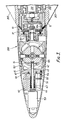
- Figure 1 is a longitudinal diametral section through the nose portion only of an aerial vehicle;
- Figure 2 is an exploded schematic perspective view of the rotor and inner gimbal of a first embodiment of roll position gyroscope according to the invention within the nose portion of the vehicle of Figure 1; and
- Figure 3 is a section corresponding to Figure 1, of a second embodiment.
- Referring first to Figure 1, the drawing shows the nose portion, i.e. forward extremity, of a
vehicle body 10 withfins 11 and a threadedaperture 12 in which is received a correspondingly threadedgyroscope mounting ring 13 which itself carries, again by threaded engagement, agyro housing 14. Threadably engaged on the front of thegyro housing 14 is thevehicle nose cone 15 and, as can be seen from Figure 1, the outer surfaces of thenose cone 15 andgyro housing 14 together define a vehicle nose profile which merges smoothly into the cylindrical shape of thevehicle body 10. - An
outer gimbal 20 of a gyroscope fits snugly within a cavity C of thehollow gyro housing 14 and rotates on a forward gimbal bearing 21 carried within aforward bulkhead 22 of thegyro housing 14, and a rear gimbal bearing 23 carried in aforward bulkhead 24 of thering 13. Theforward spigot 25 of theouter gimbal 20 is locked to the inner race of thebearing 21 by alock nut 26, and the rear gimbal spigot 27 is locked to the inner race of the rear bearing 23 by alock nut 28 spaced from the race by awasher 29. - Rotation of the rear gimbal spigot 27 relative to the
mounting ring 13 is sensed by the movement of awiping finger 30 on apotentiometer Strip 31 housed in an electrically-insulatingsubstrate 32 in apotentiometer base 33 fixed to thering 13 by a key 34. Thefinger 30 is fixed against rotation relative to the spigot 27 by its engagement with splines on the spigot, and by alock nut 35 and washer 36. signals from the potentiometer are fed to the steering apparatus of the vehicle. - The
nose cone 15 houses a plurality ofsticks 40 of a propellent material which, when ignited, generates a supply of gas for feeding to the rotor of the gyroscope to cause it to spin. Thesticks 40 of propellent are located around the circumference of a gas injector device comprising aninjection needle 42 integral with acup 43 andcompression spring 44 which is compressed between thecup 43 and asealing wall 45, which is fitted with O-rings 46 and 47 to confine gas generated by ignition of thepropellent sticks 40 to the space between thehollow nose cone 15 and theinjection cup 43. - The
sticks 40 are attached to thecup 43 by means of acharge mounting disc 56. Thecup 43 is held against the sealingwall 45 by the pressure on the end faces of thesticks 40 of anannular flange 51 at the open end of a cup-shaped can 50 accommodated in the tip of thenose cone 15, which pressure thus holds thespring 44 in a compressed state. Theinjection needle 42 extends through thesealing wall 45 and coaxially through theforward gimbal spigot 25 until its tip 52 extends into a gas injection bore 60 in theinner gimbal 61 of the gyroscope. Theouter gimbal 20 is free to rotate around theinjection needle 42 which is fixed against rotation but, because the needle tip 52 andbore 60 are of complementary, non-circular section, cannot rotate while the needle tip 52 is engaged in thebore 60. - In use of the gyroscope, the
sticks 40 of propellent are ignited by an ignition capsule accommodated within thecan 50, resulting in rapid generation of gas which passes throughapertures 54 through the wall of theinjection cup 43, so that all of the gas is channelled along theinjection needle 42 and into theinner gimbal 61 of the gyroscope. The further flow of gas within theinner gimbal 61 and the rotor of the gyroscope will be described hereinafter with reference to Figure 2. - During burning of
propellant 40, thesticks 40 are consumed. The burning ofpropellant 40 raises the pressure in thespace 55, whereby thecup 43 is forced against the sealingwall 45, hence avoiding leakage even after thesticks 40 no longer transmit the spring pressure to theflange 51. When the pressure drops, thecup 43 andneedle 42 assembly is free to move forward into the space vacated by theignition capsule 50. Thecup 43 andneedle 42 assembly continue to move forward under the influence of thespring 44 until thecharge mounting disc 56 comes to rest against the inside bore of thenose cone 15. The extent of forward movement is sufficient to carry the tip 52 of the injection needle into the bore within theforward gimbal spigot 25, and so uncage the spinning rotor of the gyroscope. - Referring now to Figure 2, the
inner gimbal 61 is located between afirst rotor mass 62 and asecond rotor mass 63. Thefirst rotor mass 62 carries by friction pressure engagement afirst nozzle ring 64 and thesecond rotor mass 63 likewise carries asecond nozzle ring 65. Not shown in Figure 2 is the shaft of the gyroscope rotor which extends between the first and second rotor masses through ashaft aperture 66 on the axis of theinner gimbal 61. The shaft is mounted by ball bearings for rotation within theshaft aperture 66, and against rotation to each of therotor masses second rotor masses - The facing
surfaces gimbal 61, but nevertheless they are sufficiently close as to inhibit any substantial transverse flow of gas between them and parallel to the faces. Incorporated in thefaces rings 53 of a form adapted to restrict the transverse flow of gas between themating faces inner gimbal 61 along theinjection bore 60 is delivered by a kidney-shaped aperture 71 to agallery 72 in thefirst rotor mass 62 and alike gallery 73 in thesecond rotor mass 63. From thegallery 72 the gas passes along sixaxial bores 74 equally spaced around the circumference of thefirst rotor mass 62 to anannular passage 75 from which the gas flows to a pair offunnels 76 in thenozzle ring 64, each serving a particular one of twonozzles 77 on the external face of thenozzle ring 64. Likewise, in thesecond rotor mass 63, gas flows along sixaxial bores 78 to anannular passage 79 and a pair of funnels 80 servingnozzles 81 in thesecond nozzle ring 65. - All four
nozzles respective nozzle rings - Figure 2 shows one of the pair of threaded
bores 82 by which theinner gimbal 61 is rotatably mounted to the outer gimbal 20 (Fig. 1). The mounting is seen more clearly in Figure 1, in which a pair of inter-gimbalmounting stub shafts 83 engage threadably with the apertures 82 (Fig. 2) in the inner gimbal and themselves carry the inner races ofinter-gimbal ball bearings 84. Figure 1 also shows that theinner gimbal 61 includes an additional bore 85 the purpose of which is to provide an inertial balance to thegas injection aperture 60, so that there is no resultant sideways force on the gyroscope shaft when the rotor is spinning. - In a first variation, the
outer gimbal 20 can be cantilevered from a position to the rear of the gyroscope rotor, in which case it is convenient to provide two spaced ball bearings along an elongated rear gimbal spigot. - In a second variation, the
injection needle 42 has a tip 52 in the form of a fork which engages a pin across the diameter of thebore 60 in theinner gimbal 61 so that the gimbal cannot rotate relative to the needle. - In a third variation, the
potentiometer base 33 is mounted on the rear face of theforward bulkhead 24, forward of thewiping finger 30. - These three variations are shown in Figure 3, in which those parts which correspond to parts of the Figure 1 and 2 embodiment are identified by the same reference numerals.
- In Figure 3, the rear gimbal spigot 27 rotates on a duplex pair of
gimbal bearings 123, and there is noforward spigot 25 or bearing 21. Thepotentiometer strip 31 andsubstrate 32 are mounted on a rearward, not forward, facing surface of thering 13. Forward of theinner gimbal 61, thewall 45 is part of thegyro housing 14 so the O-ring is unnecessary. - The
injection needle 42 extends through thewall 45 until its tip 52 extends, as in Figure 1, into a gas injection bore 60 within theinner gimbal 61. It has aslot 152 in its tip, which engages with a cagingpin 185 mounted in thegimbal 61. This engagement prevents rotation of thegimbal 61 relative to theneedle 42. - The force of the
spring 44 is resisted by a NYLONthread 151 which holds thecharge mounting disc 56 to ascrew 154 in thewall 45. Thethread 151 is consumed during the burning of thepropellant sticks 40. Thesticks 40 are ignited by anignition capsule 153 which is itself consumed during ignition of thepropellant sticks 40. - In use, the drop in pressure in the
space 55 when thesticks 40 are burnt again allows the assembly ofcup 43 andneedle 42 to move forwardly under the influence of thespring 44. The extent of such forward movement is enough to carry the tip 52 of the needle into thewall 45. With this movement, the gyro rotor becomes uncaged and free to rotate in all planes. - Figure 3 shows how the gyroscope may be housed in a
nose assembly 200 of an aerial guided missile, thenose 200 rotating relative to abody portion 201 on a bearing 202 (only part shown). Such rotation is induced by a pair of control surfaces 203. Signals from thepotentiometer strip 31 are fed byleads 204 to wiper rings 205, where they can be collected and delivered to guidance circuitry (not shown) in the body portion. This circuitry may use signals from a second potentiometer strip device mounted between the nose and the body.
Claims (10)
- A gyroscope having a housing (14), a reaction gas-turbine rotor which comprises a pair of masses (62,63), one spaced from the other at each end of a rotor shaft, an inner gimbal (61) which extends into the space between the two masses and there provides a rotational mounting for the masses in the housing (14), and means (42) for feeding to the rotor propellant gas to be discharged from the rotor to cause it to spin, wherein said means for feeding gas to the rotor comprises a gas injection needle (42) which is mounted in the housing (14) and which is movable relative to the rotor between an engaged disposition in which (i) the needle (42) extends into the space between the two masses (62,63) in a direction transverse to the rotor shaft and (ii) the tip (52) of the needle (42) engages the inner gimbal (61) to supply gas to the inner gimbal (61) for delivery to the rotor to cause the rotor to spin and cages the gyroscope by engagement with the inner gimbal (61) and a disengaged disposition in which the tip (52) of the needle (42) is disengaged from the inner gimbal (61) and the gyroscope is not caged thereby.
- A gyroscope as claimed in claim 1 wherein the inner gimbal (61) is mounted in an outer gimbal (20) for rotation about an axis at right angles to the axis of the rotor shaft, the outer gimbal (20) is mounted in the housing (14) for rotation about an outer gimbal axis perpendicular to the inner gimbal axis, wherein the needle (42) is straight, lies on the axis of rotation of the outer gimbal (20) and is fixed against rotation in the housing, wherein the engagement of the tip (52) of the needle (42) and the inner gimbal (61) is such as to prevent rotation of the inner gimbal (61) relative to the needle (42) and wherein the needle (42) moves by translation between its engaged and disengaged dispositions, in a direction along its length.
- A gyroscope as claimed in claim 2 wherein said engagement of needle (42) and inner gimbal (61) is between a pin (185) in the inner gimbal (61) transverse to the length of the needle (42) and a slot (152) in a forked tip (52) of the needle (42).
- A gyroscope as claimed in any one of claims 1 to 3 wherein the gas injection needle (42) is biased by a spring (44) out of engagement with the inner gimbal (61), but is held in engagement during delivery of the propellant gas by the pressure of said gas.
- A gyroscope as claimed in claim 4, wherein the needle (42) is held in engagement with the inner gimbal (61), until ignition of the propellant material, by a mechanical link (151) between the needle and the housing rotor (14), which link is destroyed by the combustion of the propellant material.
- A gyroscope as claimed in claim 4 wherein the needle (42) is held in engagement with the inner gimbal (61), until ignition of the propellant material, by use of the propellant material itself to transmit from the housing (14) a force of reaction to the force of the spring-bias of the needle (42).
- A gyroscope as claimed in any of claims 2 to 6 wherein the outer gimbal (20) is provided with first and second co-axial spigots (25) and (27) mounted in bearings (21,23) for rotation of the outer gimbal in the housing (14), and wherein the needle (42) extends through one of the spigots (25,27).
- A gyroscope as claimed in any of claims 2 to 6 wherein the outer gimbal (20) is provided with a single spigot (27) and is mounted in a bearing arrangement (123) in the housing (14) so that the rotor and its gimbals (61,20) are mounted on the bearing arrangement (123) in cantilever fashion, and wherein the needle (42) extends through a bore in the housing (14) opposite the bearing arrangement (123).
- A gyroscope as claimed in claim 7 or 8 further comprising means (30,31) for sensing relative rotation between the single spigot (27), or one of the first and second spigots (25,27), and the housing (14) in which the spigot is mounted.
- A gyroscope as claimed in any of the preceding claims further comprising solid propellant material (40) and an ignition capsule (50) to ignite the material to provide by combustion of the propellant material the propellant gas when required.
Applications Claiming Priority (2)
| Application Number | Priority Date | Filing Date | Title |
|---|---|---|---|
| GB8505674 | 1985-03-05 | ||
| GB8505674 | 1985-03-05 |
Publications (3)
| Publication Number | Publication Date |
|---|---|
| EP0195547A2 EP0195547A2 (en) | 1986-09-24 |
| EP0195547A3 EP0195547A3 (en) | 1989-04-19 |
| EP0195547B1 true EP0195547B1 (en) | 1991-08-07 |
Family
ID=10575476
Family Applications (1)
| Application Number | Title | Priority Date | Filing Date |
|---|---|---|---|
| EP86301492A Expired - Lifetime EP0195547B1 (en) | 1985-03-05 | 1986-03-03 | Gyroscope |
Country Status (4)
| Country | Link |
|---|---|
| US (1) | US4690007A (en) |
| EP (1) | EP0195547B1 (en) |
| CA (1) | CA1247404A (en) |
| DE (1) | DE3680692D1 (en) |
Cited By (1)
| Publication number | Priority date | Publication date | Assignee | Title |
|---|---|---|---|---|
| RU2114394C1 (en) * | 1996-10-01 | 1998-06-27 | Конструкторское бюро приборостроения | Gyroscopic instrument and process of adjustment of its drift |
Families Citing this family (8)
| Publication number | Priority date | Publication date | Assignee | Title |
|---|---|---|---|---|
| GB2221747B (en) * | 1988-08-09 | 1993-02-17 | Graviner Ltd Kidde | Apparatus and methods for producing motive power |
| RU2122709C1 (en) * | 1996-04-23 | 1998-11-27 | Конструкторское бюро приборостроения | Method and device for protecting powder reaction turbine of gyro-instrument against dynamic unbalance |
| RU2123170C1 (en) * | 1996-10-01 | 1998-12-10 | Конструкторское бюро приборостроения | Gyroscopic instrument |
| RU2125236C1 (en) * | 1997-07-08 | 1999-01-20 | Открытое акционерное общество Акционерная компания "Туламашзавод" | Powder rotor of gyroscopic instrument and gear for bench testing of powder rotor |
| RU2145056C1 (en) * | 1998-08-10 | 2000-01-27 | Открытое акционерное общество АК "Туламашзавод" | Device with vibration damper to measure dynamic characteristics of powder charges in rotary gyromotor |
| RU2155324C1 (en) * | 1998-12-03 | 2000-08-27 | Государственное унитарное предприятие Конструкторское бюро приборостроения | Gyroscopic instrument |
| RU2163711C1 (en) * | 1999-08-24 | 2001-02-27 | Открытое акционерное общество "Тульский оружейный завод" | Method of protection of bearing supports of rotor of powder gyroscopic instrument and powder gyroscopic instrument |
| US8127631B2 (en) * | 2008-09-17 | 2012-03-06 | Honeywell International Inc. | Rotor assembly including strain relief feature |
Citations (1)
| Publication number | Priority date | Publication date | Assignee | Title |
|---|---|---|---|---|
| US3393569A (en) * | 1965-05-14 | 1968-07-23 | United States Time Corp | Gyroscope |
Family Cites Families (10)
| Publication number | Priority date | Publication date | Assignee | Title |
|---|---|---|---|---|
| GB866400A (en) * | ||||
| GB764644A (en) * | ||||
| US2720602A (en) * | 1953-04-28 | 1955-10-11 | Summers Gyroscope Company | Symmetrical, temperature-compensated, direct-current motor |
| US2911832A (en) * | 1959-02-03 | 1959-11-10 | Iron Fireman Mfg Co | Gyroscope |
| US3192777A (en) * | 1962-07-05 | 1965-07-06 | United States Time Corp | High pressure gas energized gyroscope |
| DE1548396B1 (en) * | 1966-12-15 | 1970-04-30 | Messerschmitt Boelkow Blohm | Gimbal mounted gyro |
| FR2102906A5 (en) * | 1970-08-28 | 1972-04-07 | Aerospatiale | |
| FR2330998A1 (en) * | 1975-07-03 | 1977-06-03 | Realisation Electronique Et | Spring driven gyroscope for rocket guidance - contains spring motor driving spin wheel when pin is engaged |
| FR2365784A2 (en) * | 1976-09-24 | 1978-04-21 | Realisations Electroniq Et | SPRING LAUNCH GYROSCOPES IMPROVEMENTS |
| GB2117114A (en) * | 1982-03-19 | 1983-10-05 | Short Brothers Ltd | Gyroscope |
-
1986
- 1986-03-03 CA CA000503106A patent/CA1247404A/en not_active Expired
- 1986-03-03 DE DE8686301492T patent/DE3680692D1/en not_active Expired - Lifetime
- 1986-03-03 EP EP86301492A patent/EP0195547B1/en not_active Expired - Lifetime
- 1986-03-05 US US06/836,533 patent/US4690007A/en not_active Expired - Lifetime
Patent Citations (1)
| Publication number | Priority date | Publication date | Assignee | Title |
|---|---|---|---|---|
| US3393569A (en) * | 1965-05-14 | 1968-07-23 | United States Time Corp | Gyroscope |
Cited By (1)
| Publication number | Priority date | Publication date | Assignee | Title |
|---|---|---|---|---|
| RU2114394C1 (en) * | 1996-10-01 | 1998-06-27 | Конструкторское бюро приборостроения | Gyroscopic instrument and process of adjustment of its drift |
Also Published As
| Publication number | Publication date |
|---|---|
| EP0195547A2 (en) | 1986-09-24 |
| US4690007A (en) | 1987-09-01 |
| CA1247404A (en) | 1988-12-28 |
| EP0195547A3 (en) | 1989-04-19 |
| DE3680692D1 (en) | 1991-09-12 |
Similar Documents
| Publication | Publication Date | Title |
|---|---|---|
| US4690007A (en) | Gyroscope | |
| US4969397A (en) | Grenade-type projectile | |
| JP3692537B2 (en) | Missile launch and orientation system | |
| GB683484A (en) | Ammunition projectile | |
| US4676136A (en) | Apparatus for recoilless firing of projectiles from a lauching tube | |
| US2412173A (en) | Projectile | |
| GB2287439A (en) | Rocket thruster arrangement for guiding missile | |
| US3749334A (en) | Attitude compensating missile system | |
| US3167016A (en) | Rocket propelled missile | |
| US5243912A (en) | Arming delay, dual environment safe, fuze | |
| US3304029A (en) | Missile directional control system | |
| US5078336A (en) | Spin-stabilized missile with plug nozzle | |
| US3724781A (en) | Spin-stabilised rocket projectile | |
| CA2074994C (en) | Multipurpose projectile and a method of making it | |
| US4697524A (en) | After-firing safety | |
| US3970004A (en) | Spinning projectile | |
| US2741180A (en) | Armor piercing projectile | |
| EP0255776A2 (en) | Guidance apparatus for projectiles | |
| US2519905A (en) | Driver rocket | |
| US3438303A (en) | System including a tubular launching tube and a rocket provided with an outer auxiliary launching charge | |
| US3554078A (en) | Spherical missile and launching means therefor | |
| US3118377A (en) | Rocketwise propelled projectiles of the unguided type | |
| US3002455A (en) | Ballistic missile | |
| KR940015456A (en) | Safety Fuse and Shell | |
| US4406210A (en) | Jet-propelled missile with single propellant-explosive |
Legal Events
| Date | Code | Title | Description |
|---|---|---|---|
| PUAI | Public reference made under article 153(3) epc to a published international application that has entered the european phase |
Free format text: ORIGINAL CODE: 0009012 |
|
| AK | Designated contracting states |
Kind code of ref document: A2 Designated state(s): DE FR GB IT SE |
|
| PUAL | Search report despatched |
Free format text: ORIGINAL CODE: 0009013 |
|
| AK | Designated contracting states |
Kind code of ref document: A3 Designated state(s): DE FR GB IT SE |
|
| 17P | Request for examination filed |
Effective date: 19890525 |
|
| 17Q | First examination report despatched |
Effective date: 19900511 |
|
| ITF | It: translation for a ep patent filed | ||
| GRAA | (expected) grant |
Free format text: ORIGINAL CODE: 0009210 |
|
| AK | Designated contracting states |
Kind code of ref document: B1 Designated state(s): DE FR GB IT SE |
|
| REF | Corresponds to: |
Ref document number: 3680692 Country of ref document: DE Date of ref document: 19910912 |
|
| ET | Fr: translation filed | ||
| PLBE | No opposition filed within time limit |
Free format text: ORIGINAL CODE: 0009261 |
|
| STAA | Information on the status of an ep patent application or granted ep patent |
Free format text: STATUS: NO OPPOSITION FILED WITHIN TIME LIMIT |
|
| 26N | No opposition filed | ||
| EAL | Se: european patent in force in sweden |
Ref document number: 86301492.4 |
|
| REG | Reference to a national code |
Ref country code: GB Ref legal event code: IF02 |
|
| PGFP | Annual fee paid to national office [announced via postgrant information from national office to epo] |
Ref country code: GB Payment date: 20030226 Year of fee payment: 18 |
|
| PGFP | Annual fee paid to national office [announced via postgrant information from national office to epo] |
Ref country code: SE Payment date: 20030306 Year of fee payment: 18 |
|
| PGFP | Annual fee paid to national office [announced via postgrant information from national office to epo] |
Ref country code: FR Payment date: 20030310 Year of fee payment: 18 |
|
| PGFP | Annual fee paid to national office [announced via postgrant information from national office to epo] |
Ref country code: DE Payment date: 20030313 Year of fee payment: 18 |
|
| PG25 | Lapsed in a contracting state [announced via postgrant information from national office to epo] |
Ref country code: GB Free format text: LAPSE BECAUSE OF NON-PAYMENT OF DUE FEES Effective date: 20040303 |
|
| PG25 | Lapsed in a contracting state [announced via postgrant information from national office to epo] |
Ref country code: SE Free format text: LAPSE BECAUSE OF NON-PAYMENT OF DUE FEES Effective date: 20040304 |
|
| PG25 | Lapsed in a contracting state [announced via postgrant information from national office to epo] |
Ref country code: DE Free format text: LAPSE BECAUSE OF NON-PAYMENT OF DUE FEES Effective date: 20041001 |
|
| GBPC | Gb: european patent ceased through non-payment of renewal fee | ||
| EUG | Se: european patent has lapsed | ||
| PG25 | Lapsed in a contracting state [announced via postgrant information from national office to epo] |
Ref country code: FR Free format text: LAPSE BECAUSE OF NON-PAYMENT OF DUE FEES Effective date: 20041130 |
|
| REG | Reference to a national code |
Ref country code: FR Ref legal event code: ST |
|
| PG25 | Lapsed in a contracting state [announced via postgrant information from national office to epo] |
Ref country code: IT Free format text: LAPSE BECAUSE OF NON-PAYMENT OF DUE FEES;WARNING: LAPSES OF ITALIAN PATENTS WITH EFFECTIVE DATE BEFORE 2007 MAY HAVE OCCURRED AT ANY TIME BEFORE 2007. THE CORRECT EFFECTIVE DATE MAY BE DIFFERENT FROM THE ONE RECORDED. Effective date: 20050303 |