EP0195544B1 - A beverage dispensing system - Google Patents
A beverage dispensing system Download PDFInfo
- Publication number
- EP0195544B1 EP0195544B1 EP86301442A EP86301442A EP0195544B1 EP 0195544 B1 EP0195544 B1 EP 0195544B1 EP 86301442 A EP86301442 A EP 86301442A EP 86301442 A EP86301442 A EP 86301442A EP 0195544 B1 EP0195544 B1 EP 0195544B1
- Authority
- EP
- European Patent Office
- Prior art keywords
- beverage
- gas
- gases
- dispensing
- carbon dioxide
- Prior art date
- Legal status (The legal status is an assumption and is not a legal conclusion. Google has not performed a legal analysis and makes no representation as to the accuracy of the status listed.)
- Expired
Links
- 235000013361 beverage Nutrition 0.000 title claims abstract description 142
- 239000007789 gas Substances 0.000 claims abstract description 130
- CURLTUGMZLYLDI-UHFFFAOYSA-N Carbon dioxide Chemical compound O=C=O CURLTUGMZLYLDI-UHFFFAOYSA-N 0.000 claims abstract description 80
- 229910002092 carbon dioxide Inorganic materials 0.000 claims abstract description 42
- 239000001569 carbon dioxide Substances 0.000 claims abstract description 40
- IJGRMHOSHXDMSA-UHFFFAOYSA-N Atomic nitrogen Chemical compound N#N IJGRMHOSHXDMSA-UHFFFAOYSA-N 0.000 claims abstract description 36
- 229910052757 nitrogen Inorganic materials 0.000 claims abstract description 16
- 230000015572 biosynthetic process Effects 0.000 claims abstract description 7
- 239000011261 inert gas Substances 0.000 claims abstract description 7
- 238000004090 dissolution Methods 0.000 claims abstract description 3
- 235000015106 stout Nutrition 0.000 claims description 34
- 235000013405 beer Nutrition 0.000 claims description 5
- 235000019987 cider Nutrition 0.000 claims description 5
- 238000004891 communication Methods 0.000 claims description 5
- 235000014101 wine Nutrition 0.000 claims description 4
- 235000015095 lager Nutrition 0.000 claims description 3
- 238000012544 monitoring process Methods 0.000 claims description 3
- 238000007789 sealing Methods 0.000 claims description 2
- 238000000034 method Methods 0.000 abstract description 2
- 239000003570 air Substances 0.000 description 25
- 235000019985 fermented beverage Nutrition 0.000 description 6
- 229910001873 dinitrogen Inorganic materials 0.000 description 4
- QVGXLLKOCUKJST-UHFFFAOYSA-N atomic oxygen Chemical compound [O] QVGXLLKOCUKJST-UHFFFAOYSA-N 0.000 description 3
- 230000000694 effects Effects 0.000 description 3
- 239000001301 oxygen Substances 0.000 description 3
- 229910052760 oxygen Inorganic materials 0.000 description 3
- 235000014214 soft drink Nutrition 0.000 description 3
- XKRFYHLGVUSROY-UHFFFAOYSA-N Argon Chemical compound [Ar] XKRFYHLGVUSROY-UHFFFAOYSA-N 0.000 description 2
- 230000002411 adverse Effects 0.000 description 2
- 238000000855 fermentation Methods 0.000 description 2
- 230000004151 fermentation Effects 0.000 description 2
- 239000011888 foil Substances 0.000 description 2
- 239000002184 metal Substances 0.000 description 2
- 238000011144 upstream manufacturing Methods 0.000 description 2
- 229910052786 argon Inorganic materials 0.000 description 1
- 230000000721 bacterilogical effect Effects 0.000 description 1
- 230000004888 barrier function Effects 0.000 description 1
- 230000000903 blocking effect Effects 0.000 description 1
- 238000006243 chemical reaction Methods 0.000 description 1
- 230000008878 coupling Effects 0.000 description 1
- 238000010168 coupling process Methods 0.000 description 1
- 238000005859 coupling reaction Methods 0.000 description 1
- 230000003247 decreasing effect Effects 0.000 description 1
- 230000001627 detrimental effect Effects 0.000 description 1
- 230000005484 gravity Effects 0.000 description 1
- 238000003475 lamination Methods 0.000 description 1
- 239000000203 mixture Substances 0.000 description 1
- 238000005293 physical law Methods 0.000 description 1
- 239000004033 plastic Substances 0.000 description 1
- 229920003023 plastic Polymers 0.000 description 1
- 239000002985 plastic film Substances 0.000 description 1
- 230000002035 prolonged effect Effects 0.000 description 1
- 230000000717 retained effect Effects 0.000 description 1
- 239000000523 sample Substances 0.000 description 1
Images
Classifications
-
- B—PERFORMING OPERATIONS; TRANSPORTING
- B67—OPENING, CLOSING OR CLEANING BOTTLES, JARS OR SIMILAR CONTAINERS; LIQUID HANDLING
- B67D—DISPENSING, DELIVERING OR TRANSFERRING LIQUIDS, NOT OTHERWISE PROVIDED FOR
- B67D1/00—Apparatus or devices for dispensing beverages on draught
- B67D1/0042—Details of specific parts of the dispensers
- B67D1/0057—Carbonators
- B67D1/0069—Details
- B67D1/0071—Carbonating by injecting CO2 in the liquid
-
- B—PERFORMING OPERATIONS; TRANSPORTING
- B67—OPENING, CLOSING OR CLEANING BOTTLES, JARS OR SIMILAR CONTAINERS; LIQUID HANDLING
- B67D—DISPENSING, DELIVERING OR TRANSFERRING LIQUIDS, NOT OTHERWISE PROVIDED FOR
- B67D1/00—Apparatus or devices for dispensing beverages on draught
- B67D1/0003—Apparatus or devices for dispensing beverages on draught the beverage being a single liquid
- B67D1/0004—Apparatus or devices for dispensing beverages on draught the beverage being a single liquid the beverage being stored in a container, e.g. bottle, cartridge, bag-in-box, bowl
-
- B—PERFORMING OPERATIONS; TRANSPORTING
- B67—OPENING, CLOSING OR CLEANING BOTTLES, JARS OR SIMILAR CONTAINERS; LIQUID HANDLING
- B67D—DISPENSING, DELIVERING OR TRANSFERRING LIQUIDS, NOT OTHERWISE PROVIDED FOR
- B67D1/00—Apparatus or devices for dispensing beverages on draught
- B67D1/08—Details
-
- B—PERFORMING OPERATIONS; TRANSPORTING
- B67—OPENING, CLOSING OR CLEANING BOTTLES, JARS OR SIMILAR CONTAINERS; LIQUID HANDLING
- B67D—DISPENSING, DELIVERING OR TRANSFERRING LIQUIDS, NOT OTHERWISE PROVIDED FOR
- B67D1/00—Apparatus or devices for dispensing beverages on draught
- B67D1/08—Details
- B67D1/10—Pump mechanism
-
- B—PERFORMING OPERATIONS; TRANSPORTING
- B67—OPENING, CLOSING OR CLEANING BOTTLES, JARS OR SIMILAR CONTAINERS; LIQUID HANDLING
- B67D—DISPENSING, DELIVERING OR TRANSFERRING LIQUIDS, NOT OTHERWISE PROVIDED FOR
- B67D1/00—Apparatus or devices for dispensing beverages on draught
- B67D1/08—Details
- B67D1/12—Flow or pressure control devices or systems, e.g. valves, gas pressure control, level control in storage containers
-
- B—PERFORMING OPERATIONS; TRANSPORTING
- B67—OPENING, CLOSING OR CLEANING BOTTLES, JARS OR SIMILAR CONTAINERS; LIQUID HANDLING
- B67D—DISPENSING, DELIVERING OR TRANSFERRING LIQUIDS, NOT OTHERWISE PROVIDED FOR
- B67D1/00—Apparatus or devices for dispensing beverages on draught
- B67D1/08—Details
- B67D1/12—Flow or pressure control devices or systems, e.g. valves, gas pressure control, level control in storage containers
- B67D1/14—Reducing valves or control taps
-
- B—PERFORMING OPERATIONS; TRANSPORTING
- B67—OPENING, CLOSING OR CLEANING BOTTLES, JARS OR SIMILAR CONTAINERS; LIQUID HANDLING
- B67D—DISPENSING, DELIVERING OR TRANSFERRING LIQUIDS, NOT OTHERWISE PROVIDED FOR
- B67D1/00—Apparatus or devices for dispensing beverages on draught
- B67D1/08—Details
- B67D1/0801—Details of beverage containers, e.g. casks, kegs
- B67D2001/0827—Bags in box
Definitions
- This invention relates to a beverage dispensing system. More particularly, the invention concerns a system which incorporates flexible container charged with the beverage and which serves as a storage and transport facility and also as a source from which the beverage is withdrawn on demand, an example of such a flexible container is disclosed in EP-A-0053813.
- Beverage dispensing systems are well known in which a flexible container is charged with a wine, soft drink, beer or cider and fitted with a tap so that as the beverage is drawn off by gravity or pump and on demand through the tap, the container collapses under atmospheric pressure to maintain the beverage remaining therein substantially without headspace.
- containers for the aforementioned systems are formed with a flexible wall structure which is impervious to the contents, precludes the beverage from the external atmosphere and has negligible, if any, adverse effect upon the characteristics of the beverage.
- the flexible wall stuc- ture is of plastics sheeting or metal foil or laminations thereof.
- the beverages as aforementioned should have more than one volume of carbon dioxide gas (as measured at 1 atmosphere and 0°C) dissolved therein for each volume of the beverage and which gas may be retained in the beverage by a pressure on the flexible container of 1 atmosphere.
- carbon dioxide gas as measured at 1 atmosphere and 0°C
- Flexible containers of the kind mentioned above are a convenient and economical means for the storage and transportation of beverage and there is a requirement for a beverage dispensing system which includes a flexible container of the beverage that is collapsible under atmospheric pressuring during dispensing of the beverage and from which the beverage can be dispensed having an accurately controlled volume of gas dissolved therein, the volume of the dissolved gas being to an extent greater than that available with existing flexible container dispensing systems) and without changing the characteristics of the beverage as it is progressively dispensed from the container - it is an object of the present invention to satisfy this requirement.
- a beverage dispensing system which comprises a container of the beverage, said container being subjected externally to atmospheric pressure and sealing the beverage therein from external atmosphere; dispensing means in sealed communication with the beverage in the container, and means for introducing into the beverage remotely from the container and during dispensing, at least one of carbon dioxide, nitrogen (or other inert gas as herein defined) and air gases, said gas or gases being introduced to the beverage from a pressurised source of the gas or gases and through a restricted orifice so that the introduced gas or gases serve to provide or increase a dissolved gas content of the beverage to form or assist in the formation of a froth or head on the beverage as dispensed, characterised in that the container is flexible and collapses under atmospheric pressure as beverage is dispensed therefrom to maintain the beverage remaining in the container substantially without headspace and the means for introducing the gas or gases comprises a fixed orifice restrictor and a non-return valve successively thorugh which pressurised gas or gases from the pressurised
- inert gas as used throughout this Specification is meant a gas other than carbon dioxide with the following properties.
- nitrogen may be regarded as an inert gas; an example of another inert gas which may be considered suitable for the purpose of the present invention is argon.
- the system of the present invention will be located at a place of dispense for the beverage to which the flexible container of the beverage will be delivered in a sealed condition so that it will be a simple matter to pierce or break the seal and couple the container into the system.
- the beverage within the flexible container may, for practical purposes, be considered as devoid of gas (especially carbon dioxide) dissolved therein so that the entire dissolved gas content may be introduced into the beverage during its dispensing from the flexible container.
- the beverage within the flexible container may have carbon dioxide gas dissolved therein. If present, this gas is preferably at least 0.6 volumes and less than 1.5 volumes of C0 2 per volume of beverage.
- the beverage will have approximately 1.0 volumes of C0 2 per volume of beverage since, at the place of dispense, it is likely that the flexible container will be stored for dispensing at a temperature less than 15°C (so that the carbon dioxide is unlikely to be liberated at atmospheric pressure) and consequently proportionally less gas need be introduced during the dispensing.
- fermented beverages such as beer, lager, stout and cider
- the carbon dioxide dissolved in the beverage in the flexible container may result from the fermentation process.
- the gas which is introduced thereto during the dispensing will usually be carbon dioxide derived from a storage bottle or appropriate local source which may be available on the premises.
- the gas which is introduced during the dispensing will usually be nitrogen or air (relying upon the high nitrogen content in air) - the nitrogen being derived, say, from an appropriate storage bottle or the air being derived from a compressor upon demand.
- nitrogen or air relying upon the high nitrogen content in air
- the nitrogen being derived, say, from an appropriate storage bottle or the air being derived from a compressor upon demand.
- the beverage within the flexible container has carbon dioxide gas dissolved therein so that the beverage is dispensed with a mixed carbon dioxide and nitrogen gas content in accordance with the disclosure in our U.K. Patent Specificaton No. 876,628.
- the dispensing means will usually comprise a manually adjsutable valve or tap which controls the flow of beverage from the container. It is preferred that the adjustment of this tap also serves to control the introduction of the gas into the beverage during dispensing.
- the dispensing system may include a pump for withdrawal (or to assist in the withdrawal) of the beverage from the container and the operation of this pump may also be controlled by operation of the aforementioned valve or tap.
- the aforementioned control tap or valve will usually have a nozzle extending therefrom through which the beverage is dispensed.
- the gas or gases are introduced into the beverage upstream of the control tap or valve, conveniently adjacent to that tap or valve.
- a restricted orifice which is adjustable in size to very the volume of the gas flow therethrough and therefore the volume of gas which is introduced to the beverage.
- the gas is introduced into the beverage by way of a fixed orifice and subsequently through a non-return valve which non-return valve ensures that the orifice (which will necessarily be of a relatively small diameter) is not contaminated by the beverage. It is also a feature of the present invention that the pressure at which the gas is introduced into the fixed orifice is adjustable so that it can be set and maintained at a predetermined level during setting up of the system for a particular beverage and for prevalent temperature and other conditions associated with the system.
- the aforementioned fixed orifice and variable pressure arrangement for introducing the gas or gases to the beverage during dispensing provided an improved means of controlling the volume of the gas which is introduced as compared with the prior proposed arrangement in which the aforementioned orifice is adjustable whilst the pressure of the gas directed thereto remains substantially constant.
- the dispensing system immediately downstream of the position at which the gas or gases are introduced into the beverage includes means, such as baffles by which the beverage is subjected to turbulence to promote the rate at which the introduced gas or gases are absorbed by the beverage.
- the dispensing system may also include small apertures or restrictors through which the beverage is dispensed downstream or the position at which the gas or gases are introduced (particularly where the introduced gas is or comprises nitrogen) which small apertures or restrictors subject the beverage to cavitation and assist in liberating the dissolved gases to form or assist in the formation of a froth or head on the dispensed beverage.
- the beverage dispensing system may include monitoring means (such as a closed loop control arrangement) whereby the proportion of gas or gases in the beverage (following the introduction of the gas or gases thereto) is continuously monitored during dispensing and adjusted to ensure that the beverage is dispensed with a substantially constant and preset gas content.
- monitoring means such as a closed loop control arrangement
- the beverage dispensing system illustrated is primarily intended for dispensing stout from a flexible bag 1 having a plastic sheet/metal foil or other (relatively) impermeable barrier wall structure and which is intended to collapse under atmospheric pressure as the stout is drawn off.
- the dispensing system forms the end of a stout distribution process which commences, usually at a brewery, with the bag 1 being charged under atmospheric pressure with the stout; typically the bag will be capable of holding say from 3 to 100 litres of stout.
- the stout which emanates from the brewery will likely have approximately 1 volume of carbon dioxide gas dissolved in it for each volume of stout as a result of the fermentation process, and to ensure that this gas is not liberated, it is preferred that the bag is charged with the stout at a temperature less than, say, 15°C. When fully charged the bag 1 is sealed so that the stout is isolated from atmospheric air and subsequently transported for connection to the dispensing system which will be located at a place of dispense, usually (but not necessarily) a retail outlet.
- the bag will usually be supported/protected within a rigid or semi-rigid container.
- the bag 1 may be mounted on or in an appropriate support 2 and its seal broken by coupling to a pipe 3 through which the stout is to be dispensed.
- the pipe 3 can conveniently be coupled to the bag 1 by providing a tubular probe on the pipe end which breaches a diaphragm or other form of seal 4 on the bag so that the stout is in sealed communication with the pipe 3 and such communication is effected without the admission of air.
- the communication between the pipe 3 and the stout is at the lowermost position of the bag 1 so that the stout will flow naturally into the pipe 3.
- the pipe 3 communicates with an outlet nozzle 5 having a manually operated dispensing control tap 6.
- the pipe 3 can include a pump 8 which may be electrically controlled (as indicted by the line 8a) by operation of the tap 6 so that the pump is operated only when the tap is open for dispensing purposes.
- the stout is intended to be dispensed from the tap 6 having a mixture of gases, carbon dioxide and air dissolved in it - these gases serving to provide desirable characteristics to the stout as dispensed and also to form or assist in the formation of a head as the stout is dispensed into an open topped container 9; the use of such mixed gases in the dispensing of fermented beverages is discussed in our British Patent No. 876,628.
- the system includes an air compressor 10 which is operated through a line 10a under control of the tap 6 so that air under pressure is directed to the inlet 7 only when the tap 6 is open for dispensing purposes.
- Air under pressure from the compressor 10 is directed through passage 11 to the inlet 7 by way of a restricted orifice 12 and subsequently by way of a non-return valve 13.
- the restrictor 12 has a fixed orifice and serves to reduce the air pressure prior to its introduction to the stout.
- the non-return valve 13 alleviates the possibility of stout flowing from the pipe 3 into and blocking the restrictor 12.
- Means shown generally at 14 is provided for adjusting the air pressure derived from the compressor 10 and this means provides a convenient way of setting up the system for a particular stout by which it may be ensured that a required flow rate and pressure of air can be introduced into the stout by way of the fixed orifice restrictor 12.
- the air will be introduced to the beverage being dispensed so that approximately 0.002 to 0.1 volumes of nitrogen gas in the air are introduced and dissolved into each volume of stout.
- the pipe 3 can include baffles or other means shown generally at 15 downstream of the inlet 7 to create turbulence in the beverage during its flow to the nozzle 5. It will be noted that the air from the compressor 10 is introduced into the pipe 3 only on demand and immediately upstream of the tap 6 and as a consequence the relatively short period of exposure of the stout to the oxygen in the air has not been found to have any adverse effects upon the characteristics of the stout in a practical system.
- the nozzle 5 preferably includes a cavitation or restrictor plate which assists in the liberation of the dissolved gases from the stout and enhances the formation of the froth or head during dispensing in accordance with conventional practice.
- pure nitrogen can be introduced into the beverage by removing the compressor 10 and connecting the passage 11 to a bottle or other source of nitrogen gas under pressure (but again it is preferred that this pressure is adjustable at 14).
- the compressor 10 can be removed and the passage 11 coupled to a C0 2 ring main or bottle or carbon dioxide under pressure - preferably with the means 14 for adjusting that pressure so that all or a proportion of the carbon dioxide can be introduced into the beverage during dispensing.
- the system as above described can be provided with means for monitoring the proportion of gas in the beverage as dispensed and for controlling and adjusting, as necessary, the gas which is introduced to the beverage to maintain the beverage as dispensed with a substantially constant and preset gas content.
- This may be achieved by use of a closed loop control arrangement whereby a detector 16 in the pipe 3 downstream of the gas admission inlet 7 is responsive to the gas content in the beverage and is coupled (as indicated at 17) to the gas pressure adjustment means 14 to cause an adjustment, as necessary, in the gas pressure for increasing or decreasing the proportion of the introduced gas to maintain the gas content as detected at 16 subtantially constant at a preset level.
Landscapes
- Chemical & Material Sciences (AREA)
- Chemical Kinetics & Catalysis (AREA)
- Engineering & Computer Science (AREA)
- Mechanical Engineering (AREA)
- Devices For Dispensing Beverages (AREA)
- Beverage Vending Machines With Cups, And Gas Or Electricity Vending Machines (AREA)
- Distillation Of Fermentation Liquor, Processing Of Alcohols, Vinegar And Beer (AREA)
- Vacuum Packaging (AREA)
Abstract
Description
- This invention relates to a beverage dispensing system. More particularly, the invention concerns a system which incorporates flexible container charged with the beverage and which serves as a storage and transport facility and also as a source from which the beverage is withdrawn on demand, an example of such a flexible container is disclosed in EP-A-0053813. Beverage dispensing systems are well known in which a flexible container is charged with a wine, soft drink, beer or cider and fitted with a tap so that as the beverage is drawn off by gravity or pump and on demand through the tap, the container collapses under atmospheric pressure to maintain the beverage remaining therein substantially without headspace. It is appreciated that containers for the aforementioned systems are formed with a flexible wall structure which is impervious to the contents, precludes the beverage from the external atmosphere and has negligible, if any, adverse effect upon the characteristics of the beverage. Generally the flexible wall stuc- ture is of plastics sheeting or metal foil or laminations thereof. A problem encountered with known dispensing systems as aforementioned is that the beverage when dispensed has little or no gas content (either dissolved therein or liberated in the form of a froth or head on the dispensed beverage) so that the beverage as dispensed is usally regarded as "flat". For many beverages such as beer, larger, stout, cider, wine and soft drinks there is a preference by the majority of consumers that the beverage when dispensed should contain a recognisable proportion of gas, conventionally carbon dioxide. With this in mind it has hitherto been proposed, for example in our British Patent 1,063,753, to introduce into a beverage during its dispensing from a supply tank, one of carbon dioxide, nitrogen or air gas, such introduction being made from a pressurised source of the gas and through a restricted orifice of variable size so that the volume of the introduced gas could be adjusted by varying the size of the restrictor to form a required froth or head on the beverage as dispensed.
- The usual consumer preference is that the beverages as aforementioned should have more than one volume of carbon dioxide gas (as measured at 1 atmosphere and 0°C) dissolved therein for each volume of the beverage and which gas may be retained in the beverage by a pressure on the flexible container of 1 atmosphere. Whilst it is possible to charge the flexible container with beverage having carbon dioxide gas dissolved therein and to an extent much greater than, say, one volume of carbon dioxide gas per volume of beverage, it is found that during transport and storage of the container with the highly gasified beverage at ambient temperature, say 16°C or greater, the carbon dioxide gas is liberated and tends to inflate the flexible container so as to achieve an equilibrium condition in which the partial pressure of dissolved carbon dioxide gas is 1 atmosphere. This inflation will be maintained as the beverage is withdrawn from the container and the consequence is that the beverage as dispensed from a flexible container stored at atmospheric pressure will contain no greatervolume of carbon dioxide than is achieved by equilibrium with a partial pressure of 1 atmosphere of carbon dioxide. It is well known physical law that the volume of carbon dioxide gas which can be dissolved in a given volume of beverage will increase as the partial pressure of carbon dioxide which is applied to the beverage increases and decrease as the temperature of the beverage increases; bearing in mind that the flexible container is to be subjected to atmospheric pressure, it can be determined from readily available tables that at 15°C approximately one volume only of carbon dioxide gas can be dissolved in one volume of beverage. Since it frequently occurs that a beverage may be dispensed from a flexible container in a known system as aforementioned and at a temperature in excess of 15°C. it will be appreciated for the reasons previously discussed, that it is difficult to provide more than say one volume of carbon dioxide gas per volume of beverage in the beverage dispensed from said container. Even if the beverage within the container has dissolved therein one volume of carbon dioxide gas per volume of beverage, it will be apparent that this is far less than consumer preference and it is for this reason that known beverage dispensing systems of the kind previously discussed are primarily used for beverages which are acceptable to the consumer in a relatively un-gasified or flat condition. Flexible containers of the kind mentioned above are a convenient and economical means for the storage and transportation of beverage and there is a requirement for a beverage dispensing system which includes a flexible container of the beverage that is collapsible under atmospheric pressuring during dispensing of the beverage and from which the beverage can be dispensed having an accurately controlled volume of gas dissolved therein, the volume of the dissolved gas being to an extent greater than that available with existing flexible container dispensing systems) and without changing the characteristics of the beverage as it is progressively dispensed from the container - it is an object of the present invention to satisfy this requirement.
- According to the present invention there is provided a beverage dispensing system which comprises a container of the beverage, said container being subjected externally to atmospheric pressure and sealing the beverage therein from external atmosphere; dispensing means in sealed communication with the beverage in the container, and means for introducing into the beverage remotely from the container and during dispensing, at least one of carbon dioxide, nitrogen (or other inert gas as herein defined) and air gases, said gas or gases being introduced to the beverage from a pressurised source of the gas or gases and through a restricted orifice so that the introduced gas or gases serve to provide or increase a dissolved gas content of the beverage to form or assist in the formation of a froth or head on the beverage as dispensed, characterised in that the container is flexible and collapses under atmospheric pressure as beverage is dispensed therefrom to maintain the beverage remaining in the container substantially without headspace and the means for introducing the gas or gases comprises a fixed orifice restrictor and a non-return valve successively thorugh which pressurised gas or gases from the pressurised source is introduced into the beverage and means for adjusting the pressure of the introduced gas or gases prior to said gas or gases passing through the restrictor.
- By "inert gas" as used throughout this Specification is meant a gas other than carbon dioxide with the following properties.
- (i) it does not itself react chemically with the beverage;
- (ii) when applied to, or dissolved in, the beverage it does not promote or develop bacteriological reactions;
- (iii) it is not harmful to the consumer;
- (iv) it does not impair the normal taste of the beverage.
- Accordingly nitrogen may be regarded as an inert gas; an example of another inert gas which may be considered suitable for the purpose of the present invention is argon.
- The system of the present invention will be located at a place of dispense for the beverage to which the flexible container of the beverage will be delivered in a sealed condition so that it will be a simple matter to pierce or break the seal and couple the container into the system. The beverage within the flexible container may, for practical purposes, be considered as devoid of gas (especially carbon dioxide) dissolved therein so that the entire dissolved gas content may be introduced into the beverage during its dispensing from the flexible container. Alternatively however the beverage within the flexible container may have carbon dioxide gas dissolved therein. If present, this gas is preferably at least 0.6 volumes and less than 1.5 volumes of C02 per volume of beverage. Typically the beverage will have approximately 1.0 volumes of C02 per volume of beverage since, at the place of dispense, it is likely that the flexible container will be stored for dispensing at a temperature less than 15°C (so that the carbon dioxide is unlikely to be liberated at atmospheric pressure) and consequently proportionally less gas need be introduced during the dispensing. With fermented beverages such as beer, lager, stout and cider, the carbon dioxide dissolved in the beverage in the flexible container may result from the fermentation process.
- For the majority of beers, lagers, wines, ciders or soft drinks which may be dispensed from the flexible container, the gas which is introduced thereto during the dispensing will usually be carbon dioxide derived from a storage bottle or appropriate local source which may be available on the premises.
- For some fermented beverages, particularly stout, the gas which is introduced during the dispensing will usually be nitrogen or air (relying upon the high nitrogen content in air) - the nitrogen being derived, say, from an appropriate storage bottle or the air being derived from a compressor upon demand. Although the exposure of a fermented beverage to the oxygen content of air is normally considered detrimental to the beverage over a prolonged period, it will be appreciated that by the present invention the air is only introduced on demand and shortly before the beverage is dispensed and accordingly it has been found that the exposure of the beverage to the atmospheric oxygen has negligible effect upon the desired characteristics of the beverage. Where air or nitrogen gases are introduced to a fermented beverage as aforementioned, it is preferred that the beverage within the flexible container has carbon dioxide gas dissolved therein so that the beverage is dispensed with a mixed carbon dioxide and nitrogen gas content in accordance with the disclosure in our U.K. Patent Specificaton No. 876,628.
- The dispensing means will usually comprise a manually adjsutable valve or tap which controls the flow of beverage from the container. It is preferred that the adjustment of this tap also serves to control the introduction of the gas into the beverage during dispensing. The dispensing system may include a pump for withdrawal (or to assist in the withdrawal) of the beverage from the container and the operation of this pump may also be controlled by operation of the aforementioned valve or tap.
- The aforementioned control tap or valve will usually have a nozzle extending therefrom through which the beverage is dispensed. Preferably the gas or gases are introduced into the beverage upstream of the control tap or valve, conveniently adjacent to that tap or valve. It has hitherto been proposed in our British Patent 1,063,753 to introduce the gas or gases into a beverage during dispensing by way of a restricted orifice which is adjustable in size to very the volume of the gas flow therethrough and therefore the volume of gas which is introduced to the beverage. However, it is important that the volume of gas which is introduced into the beverage during dispensing can be accurately controlled to ensure that the dispensed beverage is not under or over gasified to an unacceptable level from the desired characterised and the proposed in our Patent 1,063,753 failed to achieve this. With this in mind it is a feature of the present invention that the gas is introduced into the beverage by way of a fixed orifice and subsequently through a non-return valve which non-return valve ensures that the orifice (which will necessarily be of a relatively small diameter) is not contaminated by the beverage. It is also a feature of the present invention that the pressure at which the gas is introduced into the fixed orifice is adjustable so that it can be set and maintained at a predetermined level during setting up of the system for a particular beverage and for prevalent temperature and other conditions associated with the system. It is believed that the aforementioned fixed orifice and variable pressure arrangement for introducing the gas or gases to the beverage during dispensing provided an improved means of controlling the volume of the gas which is introduced as compared with the prior proposed arrangement in which the aforementioned orifice is adjustable whilst the pressure of the gas directed thereto remains substantially constant. It is preferred that the dispensing system immediately downstream of the position at which the gas or gases are introduced into the beverage includes means, such as baffles by which the beverage is subjected to turbulence to promote the rate at which the introduced gas or gases are absorbed by the beverage. The dispensing system may also include small apertures or restrictors through which the beverage is dispensed downstream or the position at which the gas or gases are introduced (particularly where the introduced gas is or comprises nitrogen) which small apertures or restrictors subject the beverage to cavitation and assist in liberating the dissolved gases to form or assist in the formation of a froth or head on the dispensed beverage.
- The beverage dispensing system may include monitoring means (such as a closed loop control arrangement) whereby the proportion of gas or gases in the beverage (following the introduction of the gas or gases thereto) is continuously monitored during dispensing and adjusted to ensure that the beverage is dispensed with a substantially constant and preset gas content.
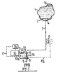
- One embodiment of a beverage dispensing system constructed and operated in accordance with the present invention will now be described, by way of example only, with reference to the accompanying illustrative drawing which diagrammatically illustrates a relatively simple and inexpensive arrangement for the dispensing of a fermented beverage.
- The beverage dispensing system illustrated is primarily intended for dispensing stout from a flexible bag 1 having a plastic sheet/metal foil or other (relatively) impermeable barrier wall structure and which is intended to collapse under atmospheric pressure as the stout is drawn off. The dispensing system forms the end of a stout distribution process which commences, usually at a brewery, with the bag 1 being charged under atmospheric pressure with the stout; typically the bag will be capable of holding say from 3 to 100 litres of stout. The stout which emanates from the brewery will likely have approximately 1 volume of carbon dioxide gas dissolved in it for each volume of stout as a result of the fermentation process, and to ensure that this gas is not liberated, it is preferred that the bag is charged with the stout at a temperature less than, say, 15°C. When fully charged the bag 1 is sealed so that the stout is isolated from atmospheric air and subsequently transported for connection to the dispensing system which will be located at a place of dispense, usually (but not necessarily) a retail outlet.
- To facilitate handling during transportation the bag will usually be supported/protected within a rigid or semi-rigid container.
- During transportation of the bag it is possible that some of the carbon dioxide within the stout may be liberated, for example as a result of the stout being subjected to a relatively high temperature and/or being disturbed - this may result in a small
carbon dioxide headspace 1a being formed in the bag but this headspace should dissipate as the gas re-dissolves when the gas is left to settle in cool conditions (which usually prevail at a dispensing site). - In the dispensing system the bag 1 may be mounted on or in an appropriate support 2 and its seal broken by coupling to a
pipe 3 through which the stout is to be dispensed. Thepipe 3 can conveniently be coupled to the bag 1 by providing a tubular probe on the pipe end which breaches a diaphragm or other form of seal 4 on the bag so that the stout is in sealed communication with thepipe 3 and such communication is effected without the admission of air. Preferably the communication between thepipe 3 and the stout is at the lowermost position of the bag 1 so that the stout will flow naturally into thepipe 3. Thepipe 3 communicates with an outlet nozzle 5 having a manually operated dispensing control tap 6. Provided in thepipe 3 upsteam of the tap 6 is a gas admission inlet 7 through which it is intended that one or more of carbon dioxide, nitrogen (or other inert gas) or air gases may be introduced into the beverage during dispensing. To assist in drawing off the beverage from the bag 1, thepipe 3 can include a pump 8 which may be electrically controlled (as indicted by theline 8a) by operation of the tap 6 so that the pump is operated only when the tap is open for dispensing purposes. - In the present example the stout is intended to be dispensed from the tap 6 having a mixture of gases, carbon dioxide and air dissolved in it - these gases serving to provide desirable characteristics to the stout as dispensed and also to form or assist in the formation of a head as the stout is dispensed into an open topped
container 9; the use of such mixed gases in the dispensing of fermented beverages is discussed in our British Patent No. 876,628. - With this in mind, air having its high content of nitrogen is introduced by way of the inlet 7 into the stout being dispensed and upon demand during dispensing. To achieve this the system includes an
air compressor 10 which is operated through aline 10a under control of the tap 6 so that air under pressure is directed to the inlet 7 only when the tap 6 is open for dispensing purposes. Air under pressure from thecompressor 10 is directed through passage 11 to the inlet 7 by way of a restricted orifice 12 and subsequently by way of a non-return valve 13. The restrictor 12 has a fixed orifice and serves to reduce the air pressure prior to its introduction to the stout. The non-return valve 13 alleviates the possibility of stout flowing from thepipe 3 into and blocking the restrictor 12. Means shown generally at 14 is provided for adjusting the air pressure derived from thecompressor 10 and this means provides a convenient way of setting up the system for a particular stout by which it may be ensured that a required flow rate and pressure of air can be introduced into the stout by way of the fixed orifice restrictor 12. In a typical stout dispensing system the air will be introduced to the beverage being dispensed so that approximately 0.002 to 0.1 volumes of nitrogen gas in the air are introduced and dissolved into each volume of stout. To assist in the dissolution of the air along with the carbon dioxide gas in the stout, thepipe 3 can include baffles or other means shown generally at 15 downstream of the inlet 7 to create turbulence in the beverage during its flow to the nozzle 5. It will be noted that the air from thecompressor 10 is introduced into thepipe 3 only on demand and immediately upstream of the tap 6 and as a consequence the relatively short period of exposure of the stout to the oxygen in the air has not been found to have any adverse effects upon the characteristics of the stout in a practical system. Where air/nitrogen gas is introduced as aforementioned, the nozzle 5 preferably includes a cavitation or restrictor plate which assists in the liberation of the dissolved gases from the stout and enhances the formation of the froth or head during dispensing in accordance with conventional practice. - It will be realised that in the stout dispensing system as above described, pure nitrogen can be introduced into the beverage by removing the
compressor 10 and connecting the passage 11 to a bottle or other source of nitrogen gas under pressure (but again it is preferred that this pressure is adjustable at 14). If the dispensing system is intended for use with a flexible bag 1 containing beverage which is to be dispensed in a highly carbonated condition then thecompressor 10 can be removed and the passage 11 coupled to a C02 ring main or bottle or carbon dioxide under pressure - preferably with themeans 14 for adjusting that pressure so that all or a proportion of the carbon dioxide can be introduced into the beverage during dispensing. - If required the system as above described can be provided with means for monitoring the proportion of gas in the beverage as dispensed and for controlling and adjusting, as necessary, the gas which is introduced to the beverage to maintain the beverage as dispensed with a substantially constant and preset gas content. This may be achieved by use of a closed loop control arrangement whereby a
detector 16 in thepipe 3 downstream of the gas admission inlet 7 is responsive to the gas content in the beverage and is coupled (as indicated at 17) to the gas pressure adjustment means 14 to cause an adjustment, as necessary, in the gas pressure for increasing or decreasing the proportion of the introduced gas to maintain the gas content as detected at 16 subtantially constant at a preset level.
Claims (13)
Priority Applications (1)
| Application Number | Priority Date | Filing Date | Title |
|---|---|---|---|
| AT86301442T ATE38209T1 (en) | 1985-03-11 | 1986-02-28 | DEVICE FOR SERVING BEVERAGES. |
Applications Claiming Priority (2)
| Application Number | Priority Date | Filing Date | Title |
|---|---|---|---|
| GB8506226 | 1985-03-11 | ||
| GB08506226A GB2172265B (en) | 1985-03-11 | 1985-03-11 | Gasifying beverage during dispensing |
Publications (2)
| Publication Number | Publication Date |
|---|---|
| EP0195544A1 EP0195544A1 (en) | 1986-09-24 |
| EP0195544B1 true EP0195544B1 (en) | 1988-10-26 |
Family
ID=10575789
Family Applications (1)
| Application Number | Title | Priority Date | Filing Date |
|---|---|---|---|
| EP86301442A Expired EP0195544B1 (en) | 1985-03-11 | 1986-02-28 | A beverage dispensing system |
Country Status (6)
| Country | Link |
|---|---|
| EP (1) | EP0195544B1 (en) |
| AT (1) | ATE38209T1 (en) |
| AU (1) | AU574272B2 (en) |
| DE (1) | DE3661006D1 (en) |
| GB (1) | GB2172265B (en) |
| IE (1) | IE57065B1 (en) |
Families Citing this family (6)
| Publication number | Priority date | Publication date | Assignee | Title |
|---|---|---|---|---|
| GB2204382A (en) * | 1987-05-01 | 1988-11-09 | Guinness Son & Co Ltd A | Fluid pressure valve |
| GB2247848B (en) * | 1990-08-17 | 1994-05-11 | Whitlenge Drink Equipment Ltd | Improvements relating to apparatus for dispensing drinks |
| EP0873966A1 (en) * | 1997-04-23 | 1998-10-28 | IMI Cornelius Inc. | Carbonation system |
| GB9800904D0 (en) * | 1998-01-17 | 1998-03-11 | Bass Plc | Improvements relating to the delivery of flavoured alcoholic beverages |
| GB9824110D0 (en) * | 1998-11-04 | 1998-12-30 | Imi Cornelius Uk Ltd | Carbonation |
| EP1829817A1 (en) * | 2006-03-04 | 2007-09-05 | C.T.L. GmbH & Co.KG | Device for dispensing beverages and mixing them with gaseous and/or flavouring substances and container for storing beverages |
Family Cites Families (5)
| Publication number | Priority date | Publication date | Assignee | Title |
|---|---|---|---|---|
| GB1063753A (en) * | 1964-06-30 | 1967-03-30 | Guinness Son & Co Ltd A | Method and means for the bulk dispensing of liquids containing gases in solution |
| GB1207155A (en) * | 1967-04-12 | 1970-09-30 | Porter Lancastrian Ltd | Adaptor for beverage dispense systems |
| AU535228B2 (en) * | 1978-02-06 | 1984-03-08 | G.H. Stuart Pty. Limited | Dispensing chilled, aerated beverages |
| DE3173922D1 (en) * | 1980-12-10 | 1986-04-03 | Cadbury Schweppes Ltd | Beverage dispensing system |
| EP0080469A1 (en) * | 1981-06-04 | 1983-06-08 | Quinvan Nominees Pty. Ltd. | Improvements in the packaging and dispensing of liquids |
-
1985
- 1985-03-11 GB GB08506226A patent/GB2172265B/en not_active Expired
-
1986
- 1986-02-28 DE DE8686301442T patent/DE3661006D1/en not_active Expired
- 1986-02-28 IE IE550/86A patent/IE57065B1/en not_active IP Right Cessation
- 1986-02-28 AT AT86301442T patent/ATE38209T1/en not_active IP Right Cessation
- 1986-02-28 EP EP86301442A patent/EP0195544B1/en not_active Expired
- 1986-04-23 AU AU56534/86A patent/AU574272B2/en not_active Ceased
Also Published As
| Publication number | Publication date |
|---|---|
| AU5653486A (en) | 1987-10-29 |
| GB8506226D0 (en) | 1985-04-11 |
| IE57065B1 (en) | 1992-04-08 |
| ATE38209T1 (en) | 1988-11-15 |
| GB2172265B (en) | 1988-02-24 |
| GB2172265A (en) | 1986-09-17 |
| DE3661006D1 (en) | 1988-12-01 |
| IE860550L (en) | 1986-09-11 |
| EP0195544A1 (en) | 1986-09-24 |
| AU574272B2 (en) | 1988-06-30 |
Similar Documents
| Publication | Publication Date | Title |
|---|---|---|
| US5029733A (en) | Beverage dispensing system | |
| EP0194787B1 (en) | A beverage dispensing system | |
| US20070248719A1 (en) | Process for producing beer | |
| GB2146705A (en) | A unit for dispensing beverage | |
| US3233779A (en) | Method and apparatus for dispensing carbonated beverages | |
| US3256802A (en) | Continuous carbonation system | |
| US4120425A (en) | Apparatus for dispensing sparkling wines | |
| US4347695A (en) | Beverage bottling method | |
| US20120058230A1 (en) | method and a system for pressurising and dispensing carbonated beverages | |
| US5011700A (en) | Syrup delivery system for carbonated beverages | |
| JPH0148811B2 (en) | ||
| US3991219A (en) | Method for mixing a carbonated beverage | |
| WO2001032549A3 (en) | Apparatus and method for dispensing a carbonated beverage with minimal/controlled foaming under system pressure | |
| EP0195544A1 (en) | A beverage dispensing system | |
| EP0447104A1 (en) | Dissolving a gas in a liquid | |
| GB2247848A (en) | Apparatus for dispensing drinks | |
| GB2247225A (en) | Method and apparatus for dispensing gasified beverages | |
| CA1297456C (en) | Beverage dispensing system and distributing process which includes sucha system | |
| AU678683B2 (en) | Flow controller for carbonated beverages | |
| NZ215899A (en) | Beverage dispensing system | |
| EP0195692A2 (en) | Dispensing of beverages | |
| EP0202053B1 (en) | Improvements in and relating to a beer container | |
| EP2241531A1 (en) | A method and system for pressurising and dispensing carbonated beverages | |
| JP7437040B2 (en) | Method for producing sparkling sake and pouring method for sparkling sake | |
| WO2019185718A1 (en) | System and method for controlling nitrogen level in a beverage container |
Legal Events
| Date | Code | Title | Description |
|---|---|---|---|
| PUAI | Public reference made under article 153(3) epc to a published international application that has entered the european phase |
Free format text: ORIGINAL CODE: 0009012 |
|
| AK | Designated contracting states |
Kind code of ref document: A1 Designated state(s): AT BE CH DE FR GB IT LI LU NL SE |
|
| 17P | Request for examination filed |
Effective date: 19870306 |
|
| 17Q | First examination report despatched |
Effective date: 19871002 |
|
| GRAA | (expected) grant |
Free format text: ORIGINAL CODE: 0009210 |
|
| AK | Designated contracting states |
Kind code of ref document: B1 Designated state(s): AT BE CH DE FR IT LI LU NL SE |
|
| REF | Corresponds to: |
Ref document number: 38209 Country of ref document: AT Date of ref document: 19881115 Kind code of ref document: T |
|
| REF | Corresponds to: |
Ref document number: 3661006 Country of ref document: DE Date of ref document: 19881201 |
|
| ET | Fr: translation filed | ||
| ITF | It: translation for a ep patent filed | ||
| PLBE | No opposition filed within time limit |
Free format text: ORIGINAL CODE: 0009261 |
|
| STAA | Information on the status of an ep patent application or granted ep patent |
Free format text: STATUS: NO OPPOSITION FILED WITHIN TIME LIMIT |
|
| 26N | No opposition filed | ||
| REG | Reference to a national code |
Ref country code: CH Ref legal event code: PFA Free format text: GUINNESS BREWING WORLDWIDE LIMITED |
|
| NLT1 | Nl: modifications of names registered in virtue of documents presented to the patent office pursuant to art. 16 a, paragraph 1 |
Owner name: GUINNESS BREWING WORLDWIDE LIMITED TE LONDEN, GROO |
|
| REG | Reference to a national code |
Ref country code: FR Ref legal event code: CD |
|
| ITTA | It: last paid annual fee | ||
| EPTA | Lu: last paid annual fee | ||
| EAL | Se: european patent in force in sweden |
Ref document number: 86301442.9 |
|
| PGFP | Annual fee paid to national office [announced via postgrant information from national office to epo] |
Ref country code: FR Payment date: 19950210 Year of fee payment: 10 |
|
| PGFP | Annual fee paid to national office [announced via postgrant information from national office to epo] |
Ref country code: AT Payment date: 19950214 Year of fee payment: 10 |
|
| PGFP | Annual fee paid to national office [announced via postgrant information from national office to epo] |
Ref country code: SE Payment date: 19950215 Year of fee payment: 10 |
|
| PGFP | Annual fee paid to national office [announced via postgrant information from national office to epo] |
Ref country code: DE Payment date: 19950222 Year of fee payment: 10 |
|
| PGFP | Annual fee paid to national office [announced via postgrant information from national office to epo] |
Ref country code: CH Payment date: 19950223 Year of fee payment: 10 |
|
| PGFP | Annual fee paid to national office [announced via postgrant information from national office to epo] |
Ref country code: NL Payment date: 19950228 Year of fee payment: 10 |
|
| PGFP | Annual fee paid to national office [announced via postgrant information from national office to epo] |
Ref country code: LU Payment date: 19950301 Year of fee payment: 10 |
|
| PGFP | Annual fee paid to national office [announced via postgrant information from national office to epo] |
Ref country code: BE Payment date: 19950410 Year of fee payment: 10 |
|
| PG25 | Lapsed in a contracting state [announced via postgrant information from national office to epo] |
Ref country code: LU Free format text: LAPSE BECAUSE OF NON-PAYMENT OF DUE FEES Effective date: 19960228 Ref country code: LI Free format text: LAPSE BECAUSE OF NON-PAYMENT OF DUE FEES Effective date: 19960228 Ref country code: CH Free format text: LAPSE BECAUSE OF NON-PAYMENT OF DUE FEES Effective date: 19960228 Ref country code: BE Effective date: 19960228 Ref country code: AT Effective date: 19960228 |
|
| PG25 | Lapsed in a contracting state [announced via postgrant information from national office to epo] |
Ref country code: SE Effective date: 19960301 |
|
| BERE | Be: lapsed |
Owner name: GUINNESS BREWING WORLDWIDE LTD Effective date: 19960228 |
|
| PG25 | Lapsed in a contracting state [announced via postgrant information from national office to epo] |
Ref country code: NL Effective date: 19960901 |
|
| REG | Reference to a national code |
Ref country code: CH Ref legal event code: PL |
|
| PG25 | Lapsed in a contracting state [announced via postgrant information from national office to epo] |
Ref country code: FR Effective date: 19961031 |
|
| NLV4 | Nl: lapsed or anulled due to non-payment of the annual fee |
Effective date: 19960901 |
|
| PG25 | Lapsed in a contracting state [announced via postgrant information from national office to epo] |
Ref country code: DE Effective date: 19961101 |
|
| EUG | Se: european patent has lapsed |
Ref document number: 86301442.9 |
|
| REG | Reference to a national code |
Ref country code: FR Ref legal event code: ST |
|
| PG25 | Lapsed in a contracting state [announced via postgrant information from national office to epo] |
Ref country code: IT Free format text: LAPSE BECAUSE OF NON-PAYMENT OF DUE FEES;WARNING: LAPSES OF ITALIAN PATENTS WITH EFFECTIVE DATE BEFORE 2007 MAY HAVE OCCURRED AT ANY TIME BEFORE 2007. THE CORRECT EFFECTIVE DATE MAY BE DIFFERENT FROM THE ONE RECORDED. Effective date: 20050228 |