EP0194376A2 - A clutch release assembly - Google Patents
A clutch release assembly Download PDFInfo
- Publication number
- EP0194376A2 EP0194376A2 EP85307897A EP85307897A EP0194376A2 EP 0194376 A2 EP0194376 A2 EP 0194376A2 EP 85307897 A EP85307897 A EP 85307897A EP 85307897 A EP85307897 A EP 85307897A EP 0194376 A2 EP0194376 A2 EP 0194376A2
- Authority
- EP
- European Patent Office
- Prior art keywords
- clutch release
- housing
- race
- bearing
- end wall
- Prior art date
- Legal status (The legal status is an assumption and is not a legal conclusion. Google has not performed a legal analysis and makes no representation as to the accuracy of the status listed.)
- Withdrawn
Links
Images

Classifications
-
- F—MECHANICAL ENGINEERING; LIGHTING; HEATING; WEAPONS; BLASTING
- F16—ENGINEERING ELEMENTS AND UNITS; GENERAL MEASURES FOR PRODUCING AND MAINTAINING EFFECTIVE FUNCTIONING OF MACHINES OR INSTALLATIONS; THERMAL INSULATION IN GENERAL
- F16D—COUPLINGS FOR TRANSMITTING ROTATION; CLUTCHES; BRAKES
- F16D23/00—Details of mechanically-actuated clutches not specific for one distinct type
- F16D23/12—Mechanical clutch-actuating mechanisms arranged outside the clutch as such
- F16D23/14—Clutch-actuating sleeves or bearings; Actuating members directly connected to clutch-actuating sleeves or bearings
- F16D23/143—Arrangements or details for the connection between the release bearing and the diaphragm
-
- F—MECHANICAL ENGINEERING; LIGHTING; HEATING; WEAPONS; BLASTING
- F16—ENGINEERING ELEMENTS AND UNITS; GENERAL MEASURES FOR PRODUCING AND MAINTAINING EFFECTIVE FUNCTIONING OF MACHINES OR INSTALLATIONS; THERMAL INSULATION IN GENERAL
- F16D—COUPLINGS FOR TRANSMITTING ROTATION; CLUTCHES; BRAKES
- F16D23/00—Details of mechanically-actuated clutches not specific for one distinct type
- F16D23/12—Mechanical clutch-actuating mechanisms arranged outside the clutch as such
- F16D23/14—Clutch-actuating sleeves or bearings; Actuating members directly connected to clutch-actuating sleeves or bearings
Definitions
- the present invention relates to a clutch release assembly particularly but not exclusively for a motor vehicle.
- Mechanical disk clutches used in motor vehicles for controllably coupling the motor vehicle engine flywheel to the gearbox input shaft, are normally biased to engagement by spring means, such as for example a diaphragm spring provided with release fingers engaged at their end with the rotatable or revolving race of a release bearing, or throw-out bearing, the non-rotatable or non-revolving race of the bearing being supported by a tubular sleeve or carrier.
- the sleeve or carrier is slidably mounted over a tubular member concentrically disposed around the driveshaft.
- the revolving race of the release bearing, or throw-out bearing is constantly engaged with the end of the clutch release fingers, even during clutch engagement.
- a relatively weak spring bias applied on the bearing carrier causes engagement of the throw-out bearing revolving race with the end of the clutch release fingers.
- the clutch is disengaged as a result of axial displacement of the throw-out bearing and bearing carrier assembly, which is effected by appropriate control means causing displacement of-the bearing carrier and throw out bearing in the direction that releases the clutch, with an accompanying considerable increase of the pressure exerted by the clutch release fingers upon the throw-out bearing revolving race.
- Controlled displacement of the bearing carrier and throw-out bearing assembly is effected by a mechanical clutch control fork lever, operated by the clutch pedal or a hydraulic actuator, or direclty by a hydraulic actuator installed concentric to the driveshaft and operated from a master cylinder in turn operated by the clutch pedal.
- the throw-out bearing and bearing carrier assembly is mechanically actuated or hydraulically actuated, it is desirable that the throw-out bearing be supported by the bearing carrier in such manner as to be able to float, to a certain amount, radially for self-alignment of the axis of rotation of the bearing revolving race with the axis of rotation of the clutch.
- the coupling between the bearing and the bearing carrier needs only hold the bearing onto the carrier prior to and during assembly on a motor vehicle in such manner that the bearing does not become accidentally separated from the carrier.
- Clutch release assemblies which incorporate self aligning bearings are known from U.K. No. 2092255A and 11260508 and an object of the present invention is to provide an improved clutch release assembly.
- a clutch release assembly comprising an axially movable carrier, a self aligning bearing supported on said carrier, said bearing having a housing provided with an end wall, a non-rotatable race displaceable laterally relative to said end wall and having a surface through which clutch releasing force is transmitted from said end wall and a rotatable race through which clutch release forces are transmitted to an actuating member of the clutch and resilient means spaced from the rotatable race and which biases the non-rotatable race towards the end wall of the housing, characterised in that seal means is arranged to provide at least a partial seal between the interior of the housing and the ambient.
- seal means is advantageous in reducing the ingress of foreign matter into the housing.
- the seal means may sealingly engage parts between which there is relative rotation and/or transverse movement.
- the seal means may include a seal which is supported by the housing and which sealingly engages an adjacent rotary part of the assembly.
- the rotatable part may be a surface of the rotatable race or a flange of a rotatable adaptor through which clutch release forces are transmitted by said rotatable race.
- the seal means may include an annular seal mounted on an end of an adapter through which clutch release forces are transmitted by said rotatable race, and sealingly engaging a surface of said housing end wall.
- the seal means may include an annular seal mounted on said non-rotatable race adjacent said housing end wall and sealingly engaging an adapter through which clutch release forces are transmitted by said rotatable race.
- the means may include an annular seal mounted on said non-rotatable race adjacent said housing end wall,said annular seal having a first lip in sealing engagement with an adaptor through which clutch release forces are transmitted by said rotatable race and a second lip in sealing engagement with said housing end wall.
- said bearing is a ball bearing and said races have each a raceway of a shape conforming to the peripheral shape of balls disposed between said raceways, and wherein a longitudinal imaginary line passing through the center of each of said balls intersects both said raceways and a radially directed imaginary line passing through the center of each of said balls intersects both said raceways.
- the resilient means acts between the non-rotatable race and an element mounted on the housing.
- the element may be annular with a cylindrical portion in abutment with the resilient means.
- Such an element may be mounted inside the housing.
- the housing is formed with an abutment surface and a portion of the resilient means is located between said element and the abutment surface.
- the resilient means may be a Belleville washer.
- a clutch release bearing 10 is illustrated mounted on the end of a bearing carrier 12, a portion of which is only shown.
- the bearing carrier 12 is in the form of a tubular or sleeve member 14 made of metal or plastic, having a central bore 16 which is disposed concentric to and slidable over a stationary tubular member, or quill 15, which is made integral or attached to, for example, the end plate of a motor vehicle gear box.
- the gear box input shaft 17 is disposed coaxial within the tubular member 15 and therefore within the central bore 16 of the bearing carrier 12.
- the bearing carrier 12 is longitudinally displaceable by a control fork, not shown.
- the control fork is mechanically connected to a clutch pedal or, in the alternative, it may be actuated by the output member of a hydraulic slave cylinder.
- the bearing carrier 12 is integral with, or attached to, the annular piston of an annular hydraulic slave cylinder mounted within the clutch bell housing, not shown, or on the end plate of the gear box, not shown concentric to the input shaft 17.
- the carrier 12 supports on one end the clutch release or throw-out bearing 10 through the intermediary of a radially extending flange 18 formed integral with the sleeve member 14 of the carrier 12.
- the throw-out bearing 10, FIGS. 2 and 3 is a thrust ball bearing 19 comprising a non-revolving outer race 20 applied on the inside surface 21 of the rear end wall 22 of an annular housing 23.
- the housing 23 is substantially cup-shaped and comprises the rear end wall 2 formed as a radially extending annular flange and an integral peripheral wall 24 extending longitudinally in the form of a cylindrical rim.
- the ball bearing 19 has a second, or revolving, race 25, a plurality of steel balls 26 being held in an annular cage 28 disposed between the non-revolving race 20 and the revolving race 25 which are each provided with a raceway 29 that, in section, forms an arc .of a circle accepting a portion of the peripheral surface of the rolling balls 26.
- An annular adapter 30 has a cylindrical portion 31 press-fitted, or otherwise fastened, within the inner bearing race 25.
- the cylindrical portion 31 of the annular adapter 30 has, at an end, a radially and outwardly directed integral flange portion or spacer 32 provided, in the example of structure illustrated, with a rounded face 33 constantly engaged with the end of the clutch release spring fingers, two of which only are shown at 34.
- the frontal portion of the throw-out bearing 10 is closed by an annular cap 35 which has a cylindrical portion 36 which is press-fitted, or otherwise fastened, within the peripherical wall 24 of the bearing housing 2 3.
- the terminal edge 37 of the annular cap cylindrical portion 36 engages the peripheral edge of a dished spring washer 38, for example a Belleville-type spring washer, whose inner edge is engaged with an end face 39 of the non-revolving race 20, such as to compress the dished spring washer 38 and urge the face 40 of the non-revolving race 20 in engagement with the inner surface 21 of the end wall 22 of the annular housing 23.
- the annular end cap 35 has a radially extending flange portion 41 which projects between the annular adapter flange 32 and the frontal surface 42 of the bearing revolving race 25, an elastomeric seal 44 being installed at the edge of the closure cap flange 41 with its terminal lip 46 in engagement with the frontal surface 42 of the revolving race 25.
- the biasing force, or pre-load 1orce, exerted by the compressed dished spring 38 against the face 39 of the non-revolving bearing race 20 engages the rear face 40 of the non-revolving race 20 with the inner surface 21 of the rear end wall or flange portion 22 of the housing 23 with enough force to pre-load slightly the surfaces in engagement, while permitting radial displacement of the ball bearing non-revolving race 20 within the housing 23 such that the ball bearing 19 is self-aligning radially, even though the housing 23 may be held against the carrier flange 18 in a fixed axial position.
- the revolving race 25 of the ball bearing 19, which contains the annular adapter 30 fitted within the race 25, is urged, by construction, towards the non-revolving race 20 by the biasing action of the seal 44 and, once installed over the carrier 12 and in the clutch release system by a return spring, such as a coil spring 47 (FIG. 1) constantly urging the face 33 of the ammlar adapter 30 against the end of the clutch release fingers 34.
- a return spring such as a coil spring 47 (FIG. 1) constantly urging the face 33 of the ammlar adapter 30 against the end of the clutch release fingers 34.
- raceways 29 of the inner rotating race 25 and of the outer non-rotating race 20 surround the periphery of the balls 26 in such a way as to fully transmit from the revolving race 25 to the non-revolving race 20 the axially directed variable thrust loads during motion of the carrier 12 for releasing the clutch arid the radially directed loads due to centrifugal force varying as a function of the velocity of revolutlor of the revolving race 25.
- the assembly consisting of the ball bearing 1 9 , the annular housing 23 and the end cap 35, forms a basic standard assembly, designated at 53 at FIG. 3, for a throw-out bearing, useful in diverse clutch structures, which is very compact in construction and which, as previously mentioned, is axially self-aligning.
- a throw-out bearing useful in diverse clutch structures, which is very compact in construction and which, as previously mentioned, is axially self-aligning.
- an appropriate adapter 30 having a flange 32 of appropriate diameter and having a face 33 of an appropriate contour for engagement with the clutch release fingers 34, which may have ends OF different shapes according to the clutch design, or OF different lengths.
- FIG. 4 illustrates a particular aspect of the invention resulting from the modular structure adopted for the clutch release or throw-out bearing lu of the invention.
- a comparison of the structure illustrated at FIG. 2 in its assembled form and at FIG. 3 in an exploded form and of the structure of the modified adapter 30 of FIG. 4 reveals differences in design and dimensions between the adapter flanges.
- the adapter 30 of FIG. 4 is fully interchangeable with the adapter 30 of FIGS. 2-3 by being provided with a cylindrical body portion 31 of outer diameter dimension allowing it to be fitted within the revolving race 25 of the ball bearing 19.
- the flange 32 is therefore capable of engagement with spring diaphragm release fingers 34' shorter than the release finger 34 of FIG. 2.
- the fingers 34' have, also for illustrative purpose, a curved end 34a which, in the course of operation of the throw-out bearing for releasing the clutch, swings and rolls to the position shown In phantom line from the position shown in full line.
- the adapter flange 32 for the purpose of accommodating the arcuate end 34a of the fingers 34', is provided with a concave finger-engaging face 33'.
- the throw-out bearing 10 is capable of installation as part of a motor vehicle clutch release mechanism for. a wide range of dimensions and designs by way of a fixed design and fixed dimension of the basic standard assembly 53 (FIG. 3) consisting of the ball bearing 19, the annular housing 23 and the end cap. 35, provided with an appropriate adapter 30 having a flange 32 of appropriate dimension and shape, custom tailored, so to speak, for the particular size and design of the clutch mechanism to be operated.
- the basic standard assembly 53 is thus able to be manufactured at.
- the bearing 10 is not completely hermetic as there is a gap between the end edge 54 of the annular adapter cylindrical portion 31 and the inner surface 21 of the end wall 22 of the housing 23.
- it is preferable to provide a seal to close the gap and this can be done simply, as shown at FIG. 5, by forming a groove 56 in the end edge 54 of the annular adapter cylindrical portion 31 in which is compressibly disposed the toot 58 of a seal 60 having a lip tip 62 in engagement with the housing end wall inner surface 21.
- the annular seal 60 may be attached to the flange 64, FIG. 6, of a support annular member or ring 66 press-fitted, for example, in the interior of the tubular body portion 31 of the adapter 30, at the end thereof, which requires the seal 60 to be installed after the adapter 30 has been press-fitted, or otherwise installed, within the ball bearing revolving race 25, prior to installing the ball bearing 19 within the housing 23 and closing the bearing 10 by way of the end cap 35.
- the seal 60 as shown at FIG.
- an annular seal 6 8 may be provided between the ball bearing non-rotating race 20 and the internal surface of the adapter cylindrical portion 3 1, the seal 68 being supported by a ring 70 press-fitted. or otherwise fastened, within the internal cylindrical surface 72 of the non-revolving ball bearing race 2U .
- Such a seal structure does not protect the surface 21 of the end wall 22 of the housing 23 and, in structure where it is desired to protect such surface a V-shaped seal 74 , FIG. 9, is provided, attached to the ring 70, having a lip tip 76 engaged with the peripheral surface of the adapter cylindrical portion 31 and a lip tip 78 engaged with the surface 21 of the end wall 22 of the housing 2 3 . in the bearing structure of FIG.
- a modifucatuib of the seal 14 mounted at the edge of the end cap 35 is illustrated at 44', its lip tip. 46' being engaged with the back surface of the adapter flange 32, rather than with the frontal surface 42 of the revolving race 25.
- FIG. 9 A further modification is also illustrated at FIG. 9, consisting in the cylindrical portion 24 of the housing 23 being provided internally with a shoulder abotment 80 limiting the depth at which the annular end cap 3 5 may be pressed into the inner wall of the cylindrical portion 24 of the housing 23 and such that the peripheral edye of the. dished spring 38 is gripped between the annular end face 37 of the cylindrical portion 36 of the annular cap 3 5 and the abutment shoulder 80 of the inner wall of the cylindrical portion 24 of the housing 23.
- the pre-load forces exerted by the dished spring 3 8 is precisely determined by design rather than being determined by linearly limiting the depth of introduction of the end cap cylindrical portion 36 within the annular housing 23.
- a quick-setting bonding compound may be used to attach the components together such as, for example, an anaerobic adhesive.
- quick-setting bonding or adhesive compound are the compounds manufactured and marketed under the trademark "LUCTIfE" by the Loctite Corporation, Newington, Connecticut.
- Such compounds are particularly useful in the bonding of cylindrical parts, having unusual high sheer strength exceeding that of conventional press-fitted parts by up to five times. They are fast curing and have excellent heat and solvent resistance characteristics, as well as providing a high sheer strength between adjoining interfaces. Curing of the adhesive is effected between 32* C and 38* C. (90 and 100°F), which are relatively low temperatures having no deleterious effect upon the elastomeric material of the seals.
- the seals 44 or 44' and the seals 60, 68 and 74 provide effective sealing between the interior of the throw-out bearing 1 0 and the ambient for preventing introduction of dirt to the interior of the bearing and escape of lubricant from the interior of the bearing, the seal lip tips permitting both relative rotary motion of the surface in engagement with the seal lip and also lateral displacement of the ball bearing 19 permitting the bearing to align itself relative to the clutch mechanism.
- the dished spring 38 is provided with apertures as shown at 82 at FIG. 9, allowing circulation of lubricant from one side of the dished spring 38 to the other..
- the dished spring 38 may be in the form of a zig-zag spring or in the form of a coil spring held in compression between the inner face of the annular end cap 35 and the face 39 of the non-revolving race 2U.
- the basic standard assembly of the throw-out bearing 10, minus the adapter 30 may be made in over-all dimensions, more particularly its outer diameter, much smaller then would generally be the case with conventional thrust bearings, and that bearing basic standard assemblies of one or two sizes may accommodate a diversity of clutch mechanism designs and dimensions simply through the expedient of providlng appropriate interchangeable annular adapters 30 havihg end flanges 32 of appropriate dimensions and shapes for engagement with the clutch release fingers 34
Landscapes
- Engineering & Computer Science (AREA)
- General Engineering & Computer Science (AREA)
- Mechanical Engineering (AREA)
- Mechanical Operated Clutches (AREA)
Abstract
@ The assembly has a cylindrical housing (23) provided with an annular end wall (22) engaged with, or mounted on, the flange (18) of a bearing carrier (12). A non-revolving race (20) of the bearing (12) is engaged against the housing end wall such as to permit lateral displacement of the race relative to the housing end wall. A revolving race (25) of the bearing supports an annular adapter (30) having an outwardly extending flange (32) engaged with the release fingers (34) of the clutch mechanism. The housing is closed by an annular end cap (35) having a flange (41) radially extending between the end face of the revolving race and the adapter flange and provided with a seal (44) having its lip engaged with the revolving race end face or with the back surface of the adapter flange. A second annular seal (60) is preferably provided between the end of the adapter opposite to the flange (32) and a surface (21) of the housing end wall (22). The seals permit rotary motion between the bearing elements and transverse motion such as to allow the bearing to self-align within the housing. A Belleville spring (38) is disposed within the housing such as to bias the non-revolving race end face into engagement with the housing end wall (22), with a force sufficient to hold the surfaces in engagement but insufficient to prevent lateral motion of the non-revolving race relative to the housing.
Description
- The present invention relates to a clutch release assembly particularly but not exclusively for a motor vehicle.
- Mechanical disk clutches used in motor vehicles, for controllably coupling the motor vehicle engine flywheel to the gearbox input shaft, are normally biased to engagement by spring means, such as for example a diaphragm spring provided with release fingers engaged at their end with the rotatable or revolving race of a release bearing, or throw-out bearing, the non-rotatable or non-revolving race of the bearing being supported by a tubular sleeve or carrier. The sleeve or carrier is slidably mounted over a tubular member concentrically disposed around the driveshaft.
- The revolving race of the release bearing, or throw-out bearing is constantly engaged with the end of the clutch release fingers, even during clutch engagement. As long as the clutch is engaged, a relatively weak spring bias applied on the bearing carrier causes engagement of the throw-out bearing revolving race with the end of the clutch release fingers. The clutch is disengaged as a result of axial displacement of the throw-out bearing and bearing carrier assembly, which is effected by appropriate control means causing displacement of-the bearing carrier and throw out bearing in the direction that releases the clutch, with an accompanying considerable increase of the pressure exerted by the clutch release fingers upon the throw-out bearing revolving race. Controlled displacement of the bearing carrier and throw-out bearing assembly is effected by a mechanical clutch control fork lever, operated by the clutch pedal or a hydraulic actuator, or direclty by a hydraulic actuator installed concentric to the driveshaft and operated from a master cylinder in turn operated by the clutch pedal.
- Whether the throw-out bearing and bearing carrier assembly is mechanically actuated or hydraulically actuated, it is desirable that the throw-out bearing be supported by the bearing carrier in such manner as to be able to float, to a certain amount, radially for self-alignment of the axis of rotation of the bearing revolving race with the axis of rotation of the clutch. In view of the constant spring bias exerted upon the bearing after installation in a motor vehicle, the coupling between the bearing and the bearing carrier needs only hold the bearing onto the carrier prior to and during assembly on a motor vehicle in such manner that the bearing does not become accidentally separated from the carrier.
- Clutch release assemblies which incorporate self aligning bearings are known from U.K. No. 2092255A and 11260508 and an object of the present invention is to provide an improved clutch release assembly.
- According to the invention, there is provided a clutch release assembly comprising an axially movable carrier, a self aligning bearing supported on said carrier, said bearing having a housing provided with an end wall, a non-rotatable race displaceable laterally relative to said end wall and having a surface through which clutch releasing force is transmitted from said end wall and a rotatable race through which clutch release forces are transmitted to an actuating member of the clutch and resilient means spaced from the rotatable race and which biases the non-rotatable race towards the end wall of the housing, characterised in that seal means is arranged to provide at least a partial seal between the interior of the housing and the ambient.
- The use of the seal means is advantageous in reducing the ingress of foreign matter into the housing.
- The seal means may sealingly engage parts between which there is relative rotation and/or transverse movement.
- The seal means may include a seal which is supported by the housing and which sealingly engages an adjacent rotary part of the assembly. In such a case the rotatable part may be a surface of the rotatable race or a flange of a rotatable adaptor through which clutch release forces are transmitted by said rotatable race.
- The seal means may sealingly engage parts between which there is relative rotation and/or transverse movement.
- The seal means may include a seal which is supported by the housing and which sealingly engages an adjacent rotary part of the assembly. In such a case, the rotatable part may be a surface of the rotatable race or a flange of a rotatable adaptor through which clutch release forces are transmitted by said rotatable race.
- The seal means may include an annular seal mounted on an end of an adapter through which clutch release forces are transmitted by said rotatable race, and sealingly engaging a surface of said housing end wall.
- Alternatively, the seal means may include an annular seal mounted on said non-rotatable race adjacent said housing end wall and sealingly engaging an adapter through which clutch release forces are transmitted by said rotatable race.
- In another case the means may include an annular seal mounted on said non-rotatable race adjacent said housing end wall,said annular seal having a first lip in sealing engagement with an adaptor through which clutch release forces are transmitted by said rotatable race and a second lip in sealing engagement with said housing end wall.
- Preferably, said bearing is a ball bearing and said races have each a raceway of a shape conforming to the peripheral shape of balls disposed between said raceways, and wherein a longitudinal imaginary line passing through the center of each of said balls intersects both said raceways and a radially directed imaginary line passing through the center of each of said balls intersects both said raceways.
- In one embodiment the resilient means acts between the non-rotatable race and an element mounted on the housing. The element may be annular with a cylindrical portion in abutment with the resilient means. Such an element may be mounted inside the housing. Preferably the housing is formed with an abutment surface and a portion of the resilient means is located between said element and the abutment surface.
- The resilient means may be a Belleville washer.
- Clutch release assemblies in accordance with the invention will now be described by way of example with reference to the accompanying drawings in which:
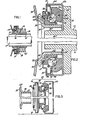
- FIG. 1 is a partial longitudinal sectional view of a clutch release or throw-out bearing and bearing carrier assembly illustrating an example of bearing according to the present invention;
- FIG. 2 is a partial longitudinal sectional view thereof, but shown at an enlarged scale to illustrate details of structure;
- FIG. 3 is an exploded view of the bearing forming part of the assembly of FIGS. 1 and 2;
- FIG. 4 is a view of one of the components of the assembly of FIGS. 2 and 3, and showing a modification thereof;
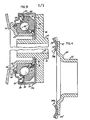
- FIGS. 5-8 are partial views similar to Fig. 2 but illustrating further modification of the invention; and
- FIG. 9 is a view similar to FIG. 2, but showing a modification thereof.
- Referring to the drawing and more particularly to FIG. 1, a clutch release bearing 10 is illustrated mounted on the end of a bearing
carrier 12, a portion of which is only shown. Thebearing carrier 12 is in the form of a tubular orsleeve member 14 made of metal or plastic, having acentral bore 16 which is disposed concentric to and slidable over a stationary tubular member, or quill 15, which is made integral or attached to, for example, the end plate of a motor vehicle gear box. The gear box input shaft 17 is disposed coaxial within the tubular member 15 and therefore within thecentral bore 16 of the bearingcarrier 12. In some installations, the bearingcarrier 12 is longitudinally displaceable by a control fork, not shown. The control fork is mechanically connected to a clutch pedal or, in the alternative, it may be actuated by the output member of a hydraulic slave cylinder. In other installations, thebearing carrier 12 is integral with, or attached to, the annular piston of an annular hydraulic slave cylinder mounted within the clutch bell housing, not shown, or on the end plate of the gear box, not shown concentric to the input shaft 17. - As best shown at FIG. 2, the
carrier 12 supports on one end the clutch release or throw-out bearing 10 through the intermediary of a radially extendingflange 18 formed integral with thesleeve member 14 of thecarrier 12. The throw-out bearing 10, FIGS. 2 and 3, is a thrust ball bearing 19 comprising a non-revolvingouter race 20 applied on theinside surface 21 of therear end wall 22 of anannular housing 23. Thehousing 23 is substantially cup-shaped and comprises therear end wall 2 formed as a radially extending annular flange and an integralperipheral wall 24 extending longitudinally in the form of a cylindrical rim. The ball bearing 19 has a second, or revolving,race 25, a plurality ofsteel balls 26 being held in anannular cage 28 disposed between thenon-revolving race 20 and the revolvingrace 25 which are each provided with araceway 29 that, in section, forms an arc .of a circle accepting a portion of the peripheral surface of therolling balls 26. - An
annular adapter 30 has acylindrical portion 31 press-fitted, or otherwise fastened, within the inner bearingrace 25. Thecylindrical portion 31 of theannular adapter 30 has, at an end, a radially and outwardly directed integral flange portion or spacer 32 provided, in the example of structure illustrated, with arounded face 33 constantly engaged with the end of the clutch release spring fingers, two of which only are shown at 34. The frontal portion of the throw-out bearing 10 is closed by anannular cap 35 which has acylindrical portion 36 which is press-fitted, or otherwise fastened, within theperipherical wall 24 of the bearing housing 23. - The
terminal edge 37 of the annular capcylindrical portion 36 engages the peripheral edge of a dishedspring washer 38, for example a Belleville-type spring washer, whose inner edge is engaged with anend face 39 of thenon-revolving race 20, such as to compress the dishedspring washer 38 and urge theface 40 of thenon-revolving race 20 in engagement with theinner surface 21 of theend wall 22 of theannular housing 23. The annular end cap 35 has a radially extending flange portion 41 which projects between theannular adapter flange 32 and thefrontal surface 42 of thebearing revolving race 25, an elastomeric seal 44 being installed at the edge of the closure cap flange 41 with itsterminal lip 46 in engagement with thefrontal surface 42 of the revolvingrace 25. - The biasing force, or pre-load 1orce, exerted by the compressed dished
spring 38 against theface 39 of the non-revolving bearingrace 20 engages therear face 40 of thenon-revolving race 20 with theinner surface 21 of the rear end wall orflange portion 22 of thehousing 23 with enough force to pre-load slightly the surfaces in engagement, while permitting radial displacement of the ball bearing non-revolvingrace 20 within thehousing 23 such that the ball bearing 19 is self-aligning radially, even though thehousing 23 may be held against thecarrier flange 18 in a fixed axial position. 'For some applications, it may be found desirable to hold thehousing 23 of the throw-out bearing 10 against the carrier flange i8 in such manner that thehousing 23 is also radially displaceable, with the result that an additional degree of freedom is provided for axial self-alignment of the throw-out bearing 10 relative to the clutch mechanism. In the structure of FIG. 2, the revolvingrace 25 of the ball bearing 19, which contains theannular adapter 30 fitted within therace 25, is urged, by construction, towards thenon-revolving race 20 by the biasing action of the seal 44 and, once installed over thecarrier 12 and in the clutch release system by a return spring, such as a coil spring 47 (FIG. 1) constantly urging theface 33 of theammlar adapter 30 against the end of theclutch release fingers 34. - A particular aspect of the ball bearing 19 which is important to be noted is that the
raceways 29 of the inner rotatingrace 25 and of theouter non-rotating race 20 surround the periphery of theballs 26 in such a way as to fully transmit from the revolvingrace 25 to thenon-revolving race 20 the axially directed variable thrust loads during motion of thecarrier 12 for releasing the clutch arid the radially directed loads due to centrifugal force varying as a function of the velocity of revolutlor of the revolvingrace 25. Such an arrangement is graphically represented at FIG. 2 by an axial imaginary line 48 representing the axis of application of the variable thrust force passing through the center 50 of theballs 26 and intersecting bothraceways 29, and by a radialimaginary line 52 representing the axis of application of the variable centrifugal force, also passing through the center 50 of the balls 26 and intersecting theraceways 29, such that thebearing 10 is capable of transfering both longitudinal thrust loads and radial centrifugal loads under all conditions, without urging the balls 26 over the edge of theraceways 29. - The assembly consisting of the ball bearing 19, the
annular housing 23 and theend cap 35, forms a basic standard assembly, designated at 53 at FIG. 3, for a throw-out bearing, useful in diverse clutch structures, which is very compact in construction and which, as previously mentioned, is axially self-aligning. For adapting the throw-out bearing lU to a wide range of different clutch and clutch release finger designs all that is required is to press-fit, or otherwise attach to the ball bearing revolving race 25 anappropriate adapter 30 having aflange 32 of appropriate diameter and having aface 33 of an appropriate contour for engagement with theclutch release fingers 34, which may have ends OF different shapes according to the clutch design, or OF different lengths. - FIG. 4 illustrates a particular aspect of the invention resulting from the modular structure adopted for the clutch release or throw-out bearing lu of the invention. A comparison of the structure illustrated at FIG. 2 in its assembled form and at FIG. 3 in an exploded form and of the structure of the modified
adapter 30 of FIG. 4 reveals differences in design and dimensions between the adapter flanges. Theadapter 30 of FIG. 4, however, is fully interchangeable with theadapter 30 of FIGS. 2-3 by being provided with acylindrical body portion 31 of outer diameter dimension allowing it to be fitted within the revolvingrace 25 of the ball bearing 19. However, the outwardly extendingradial flange 32 of the adapter of FIG. 4 is shown, for illustrative purpose only, ns extending outwardly further than the adapter flange 32 of the structure of FIGS. 2-3. Being of an over-all larger diameter, theflange 32 is therefore capable of engagement with spring diaphragm release fingers 34' shorter than therelease finger 34 of FIG. 2. The fingers 34' have, also for illustrative purpose, acurved end 34a which, in the course of operation of the throw-out bearing for releasing the clutch, swings and rolls to the position shown In phantom line from the position shown in full line. Theadapter flange 32, for the purpose of accommodating thearcuate end 34a of the fingers 34', is provided with a concave finger-engaging face 33'. Thus, the throw-out bearing 10 is capable of installation as part of a motor vehicle clutch release mechanism for. a wide range of dimensions and designs by way of a fixed design and fixed dimension of the basic standard assembly 53 (FIG. 3) consisting of theball bearing 19, the annular housing 23 and the end cap. 35, provided with anappropriate adapter 30 having aflange 32 of appropriate dimension and shape, custom tailored, so to speak, for the particular size and design of the clutch mechanism to be operated. The basicstandard assembly 53 is thus able to be manufactured at. relatively low cost in tooling and materials, and a large inventory of diverse sizes of the basic standard assembly needs not be carried by the manufacturer, as an inventory ofdiverse adapters 30, each of particular dimension and shape of theflange 32, is all that is required to make the throw-out bearing 10 capable of accommodating a variety of disc clutch designs and dimensions. - In the structure of FIG. 2, the
bearing 10 is not completely hermetic as there is a gap between the end edge 54 of the annular adaptercylindrical portion 31 and theinner surface 21 of theend wall 22 of thehousing 23. For some applications, it is preferable to provide a seal to close the gap, and this can be done simply, as shown at FIG. 5, by forming agroove 56 in theend edge 54 of the annular adaptercylindrical portion 31 in which is compressibly disposed thetoot 58 of aseal 60 having a lip tip 62 in engagement with the housing end wallinner surface 21. - Alternatively, the
annular seal 60 may be attached to theflange 64, FIG. 6, of a support annular member orring 66 press-fitted, for example, in the interior of thetubular body portion 31 of theadapter 30, at the end thereof, which requires theseal 60 to be installed after theadapter 30 has been press-fitted, or otherwise installed, within the ballbearing revolving race 25, prior to installing theball bearing 19 within thehousing 23 and closing thebearing 10 by way of theend cap 35. Preferably, theseal 60, as shown at FIG. 7, is attached to a ring 66' which is press-fitted, or otherwise fastened, peripherally at the end of the adaptercylindrical portion 31, and thus forms part of theadapter 30 itself, which may thus be press-fitted within the ball bearing inner revolvingrace 25, without interierence. after the bearing basic standard assembly is fully assembled. - As illustrated at FIG. 8, an annular seal 68 may be provided between the ball bearing
non-rotating race 20 and the internal surface of the adapter cylindrical portion 31, the seal 68 being supported by a ring 70 press-fitted. or otherwise fastened, within the internal cylindrical surface 72 of the non-revolving ball bearing race 2U. Such a seal structure does not protect the surface 21 of theend wall 22 of thehousing 23 and, in structure where it is desired to protect such surface a V-shaped seal 74, FIG. 9, is provided, attached to the ring 70, having a lip tip 76 engaged with the peripheral surface of the adaptercylindrical portion 31 and a lip tip 78 engaged with thesurface 21 of theend wall 22 of thehousing 23. in the bearing structure of FIG. 9, a modifucatuib of theseal 14 mounted at the edge of theend cap 35 is ilustrated at 44', its lip tip. 46' being engaged with the back surface of theadapter flange 32, rather than with thefrontal surface 42 of the revolvingrace 25. - A further modification is also illustrated at FIG. 9, consisting in the
cylindrical portion 24 of thehousing 23 being provided internally with ashoulder abotment 80 limiting the depth at which the annular end cap 35 may be pressed into the inner wall of the cylindrical portion 24 of thehousing 23 and such that the peripheral edye of the. dishedspring 38 is gripped between the annular end face 37 of thecylindrical portion 36 of the annular cap 35 and theabutment shoulder 80 of the inner wall of thecylindrical portion 24 of thehousing 23. In this manner, the pre-load forces exerted by the dished spring 38 is precisely determined by design rather than being determined by linearly limiting the depth of introduction of the end capcylindrical portion 36 within theannular housing 23. - Instead of press-fitting the
adapter 30 within the bail bearing inner revolvingrace 25, and iustead of press-fitting theannular end cap 35 within thecylindrical wall 24 of thehousing 23, a quick-setting bonding compound may be used to attach the components together such as, for example, an anaerobic adhesive. Examples of such quick-setting bonding or adhesive compound are the compounds manufactured and marketed under the trademark "LUCTIfE" by the Loctite Corporation, Newington, Connecticut. Such compounds are particularly useful in the bonding of cylindrical parts, having unusual high sheer strength exceeding that of conventional press-fitted parts by up to five times. They are fast curing and have excellent heat and solvent resistance characteristics, as well as providing a high sheer strength between adjoining interfaces. Curing of the adhesive is effected between 32* C and 38* C. (90 and 100°F), which are relatively low temperatures having no deleterious effect upon the elastomeric material of the seals. - It will be appreciated that the seals 44 or 44' and the
seals 60, 68 and 74 provide effective sealing between the interior of the throw-out bearing 10 and the ambient for preventing introduction of dirt to the interior of the bearing and escape of lubricant from the interior of the bearing, the seal lip tips permitting both relative rotary motion of the surface in engagement with the seal lip and also lateral displacement of theball bearing 19 permitting the bearing to align itself relative to the clutch mechanism. Preferably, the dished spring 38 is provided with apertures as shown at 82 at FIG. 9, allowing circulation of lubricant from one side of the dishedspring 38 to the other.. It will be appreciated that the dishedspring 38 may be in the form of a zig-zag spring or in the form of a coil spring held in compression between the inner face of theannular end cap 35 and theface 39 of the non-revolving race 2U. - It will be further appreciated that the basic standard assembly of the throw-
out bearing 10, minus the adapter 30, may be made in over-all dimensions, more particularly its outer diameter, much smaller then would generally be the case with conventional thrust bearings, and that bearing basic standard assemblies of one or two sizes may accommodate a diversity of clutch mechanism designs and dimensions simply through the expedient of providlng appropriate interchangeableannular adapters 30havihg end flanges 32 of appropriate dimensions and shapes for engagement with the clutch release fingers 34 - Having thus described the present invention by way of examples of structure well designed to accomplish the objects of the invention, modifications whereof will be apparent to those skilled in the art, what is claimed as new is as follows:
Claims (14)
1. A clutch release assembly comprising an axially movable carrier (12), a self aligning bearing (53) supported on said carrier, said bearing having a housing (23) provided with an end wall (22), a non-rotatable race (20) displaceable laterally relative to said end wall and having a surface through which clutch releasing force is transmitted from said end wall (22) and a rotatable race (25) through which clutch release forces are transmitted to an actuating member (34) of the clutch, and resilient means (38) spaced from the rotatable race and which biasses the non-rotatable race (20) towards the end wall of the housing, characterised in that seal means (55,60; 68;44'74) is arranged to provide at least a partial seal between the interior of the housing (23) and the ambient.
2. A clutch release assembly according to Claim 1 characterised in that said seal means (44,60; 68;44',74) sealingly engages parts (35,25; 31,22; 31,20; 35,32) between which there is relative rotation.
3. A clutch release mechanism according to Claim 1 or 2 in which said seal means (44,60;68;44,74) sealingly engages parts (35,25; 31,22;31,20 35,32) between which there is relative transverse movement.
4. A clutch release mechanism according to Claim 2 or 3 characterised in that said rotatable part is a surface of the rotatable race (25) or a flange (32) of a rotatable adaptor (30) through which clutch release forces are transmitted by said rotatable race.
5. A clutch release assembly according to Claim 4, characterised in that said rotatable part is a surface of the rotatable race (25) or a flange (32) of a rotatable adaptor (30) through which clutch release forces are transmitted by said rotatable race.
6. A clutch release assembly according to any preceding claim characterised in that said seal means includes an annular seal (60) mounted on an end of an adapter through which clutch release forces are transmitted by said rotatable race (20) and sealingly engaging a surface (21) of said housing end wall (22).
7. A clutch release assembly according to any of claims 1 to 5 characterised in that said seal means includes an annular seal (68) mounted on said non-rotatable race (20) adjacent said housing end wall (22) and sealingly engaging an adapter (30) through which clutch release forces are transmitted by said rotatable race (20).
8. A clutch release assembly according to any Claims 1 to 5 characterised in that said seal means includes an annular seal (74) mounted on said non-rotatable race (20) adjacent said housing end wall (22) said annular seal having a first lip (76) in sealing engagement with an adaptor through which clutch release forces are transmitted by said rotatable race (20) and a second lip (78) in sealing engagement with said housing end wall (22).
9. A clutch release assembly according to any preceding claim characterised in that said bearing is a ball bearing and said races (20,23) have each a raceway (29) of a shape conforming to the peripheral shape of balls (26) disposed between said raceways, and wherein a longitudinal imaginary line (48) passing through the center of each of said balls (28) intersects both said raceways (29) and a radially directed imaginary line (52) passing through the center of each of said balls (26) intersects both said raceways (29).
10. A clutch release assembly according to any preceding claim characterised in that resilient means (38) acts between the non-rotatable race (20) and an element (35) mounted on the housing (23).
11. A clutch release assembly according to Claim 10, characterised in that the element (35) is annular and has a cylindrical portion (36) in abutment with the resilient means (38).
12. A clutch release assembly according to Claim 10 or 11 characterised in that the element (35) is mounted inside the housing (23).
13. A clutch release assembly according to Claim 12 characterised in that the housing (23) is formed with an abutment surface (80) and a portion of the resilient means is located between said element (35) and the abutment surface.
14. A clutch release assembly according to any preceding claim characterised in that the resilient means is a Belleville washer (38) having its inner periphery in abutment with the non-rotatable race (20).
Applications Claiming Priority (2)
| Application Number | Priority Date | Filing Date | Title |
|---|---|---|---|
| US709089 | 1985-03-07 | ||
| US06/709,089 US4771874A (en) | 1984-03-01 | 1985-03-07 | Self-aligning bearing |
Publications (2)
| Publication Number | Publication Date |
|---|---|
| EP0194376A2 true EP0194376A2 (en) | 1986-09-17 |
| EP0194376A3 EP0194376A3 (en) | 1987-01-14 |
Family
ID=24848439
Family Applications (1)
| Application Number | Title | Priority Date | Filing Date |
|---|---|---|---|
| EP85307897A Withdrawn EP0194376A3 (en) | 1985-03-07 | 1985-10-31 | A clutch release assembly |
Country Status (3)
| Country | Link |
|---|---|
| US (1) | US4771874A (en) |
| EP (1) | EP0194376A3 (en) |
| JP (1) | JPS61148926U (en) |
Cited By (2)
| Publication number | Priority date | Publication date | Assignee | Title |
|---|---|---|---|---|
| WO2007006394A1 (en) * | 2005-07-13 | 2007-01-18 | Schaeffler Kg | Clutch release bearing in contact with a disk spring |
| EP3029348A4 (en) * | 2013-07-29 | 2017-05-31 | NTN Corporation | Clutch release bearing device |
Families Citing this family (7)
| Publication number | Priority date | Publication date | Assignee | Title |
|---|---|---|---|---|
| US4960193A (en) * | 1989-01-27 | 1990-10-02 | Ina Bearing Company, Inc. | Concentric slave cylinder |
| GB2338766B (en) * | 1998-03-20 | 2002-12-31 | Luk Lamellen & Kupplungsbau | Release bearing |
| US6374724B1 (en) | 2000-03-21 | 2002-04-23 | Automotive Products (Usa) Inc. | Concentrically mounted hydraulic clutch slave cylinder |
| DE10162313B4 (en) * | 2001-12-19 | 2018-10-11 | Trützschler GmbH & Co Kommanditgesellschaft | Roller for spinning preparation machine, e.g. Drum, taker or the like, for a card |
| DE102006059300A1 (en) * | 2006-12-15 | 2008-06-19 | Schaeffler Kg | clutch release |
| US7712595B2 (en) * | 2007-02-20 | 2010-05-11 | Eaton Corporation | Clutch release bearing assembly |
| CN105065502A (en) * | 2015-07-14 | 2015-11-18 | 安徽江淮汽车股份有限公司 | Automobile drive system and clutch release bearing assembly thereof |
Family Cites Families (13)
| Publication number | Priority date | Publication date | Assignee | Title |
|---|---|---|---|---|
| FR1467848A (en) * | 1965-12-20 | 1967-02-03 | Ferodo Sa | Release bearing, and clutch comprising it |
| DE6904329U (en) * | 1969-02-05 | 1969-06-26 | Fichtel & Sachs Ag | SEAL FOR ROLLER BEARING |
| DE2222085B2 (en) * | 1972-05-05 | 1980-09-18 | Industriewerk Schaeffler Ohg, 8522 Herzogenaurach | Clutch withdrawal bearing assembly - has inner race with flange of drawn sheet metal with annular bead and collar |
| US3870384A (en) * | 1972-09-15 | 1975-03-11 | Federal Mogul Corp | Preloading and sealing system for clutch bearings |
| DE2329911A1 (en) * | 1973-06-12 | 1975-01-09 | Joerg Schwarzbich | Press-stud insertion of bearing rings in inclined ball bearings - moulded lips formed on the plastic roller body cage |
| US3920107A (en) * | 1973-08-16 | 1975-11-18 | Fichtel & Sachs Ag | Self-aligning clutch release bearing arrangement |
| GB2046395B (en) * | 1979-02-06 | 1983-02-16 | Ransome Hoffmann Pollard | Clutch release mechanisms |
| FR2465119A1 (en) * | 1979-09-10 | 1981-03-20 | Ferodo Sa | STOP CLUTCH |
| DE3136548A1 (en) * | 1981-09-15 | 1983-03-31 | LuK Lamellen und Kupplungsbau GmbH, 7580 Bühl | PRESSURE-OPERATED DISCONNECTING DEVICE FOR CLUTCHES, ESPECIALLY FOR MOTOR VEHICLE CLUTCHES |
| FR2544429B1 (en) * | 1983-04-15 | 1985-08-02 | Valeo | METHOD FOR MOUNTING A RELEASE STOPPER, AND CORRESPONDING RELEASE STOPPER, PARTICULARLY FOR A MOTOR VEHICLE |
| US4555007A (en) * | 1983-12-15 | 1985-11-26 | Aetna Bearing Company | Self adjusting thrust, low angular contact bearing |
| FR2559861B1 (en) * | 1984-02-21 | 1989-04-07 | Valeo | RELEASE STOP, PARTICULARLY FOR A MOTOR VEHICLE, WITH IMPROVED MOUNTING |
| US4566578A (en) * | 1984-06-04 | 1986-01-28 | Automotive Products Plc | Clutch throw-out bearing and bearing carrier assembly |
-
1985
- 1985-03-07 US US06/709,089 patent/US4771874A/en not_active Expired - Fee Related
- 1985-10-31 EP EP85307897A patent/EP0194376A3/en not_active Withdrawn
- 1985-12-25 JP JP1985204801U patent/JPS61148926U/ja active Pending
Cited By (4)
| Publication number | Priority date | Publication date | Assignee | Title |
|---|---|---|---|---|
| WO2007006394A1 (en) * | 2005-07-13 | 2007-01-18 | Schaeffler Kg | Clutch release bearing in contact with a disk spring |
| US8286775B2 (en) | 2005-07-13 | 2012-10-16 | Schaeffler Technologies AG & Co. KG | Clutch release bearing in contact with a disk spring |
| EP3029348A4 (en) * | 2013-07-29 | 2017-05-31 | NTN Corporation | Clutch release bearing device |
| US10107339B2 (en) | 2013-07-29 | 2018-10-23 | Ntn Corporation | Clutch release bearing device |
Also Published As
| Publication number | Publication date |
|---|---|
| JPS61148926U (en) | 1986-09-13 |
| US4771874A (en) | 1988-09-20 |
| EP0194376A3 (en) | 1987-01-14 |
Similar Documents
| Publication | Publication Date | Title |
|---|---|---|
| CA1275676C (en) | Clutch release bearing | |
| US3788437A (en) | Clutch release bearing | |
| US4869355A (en) | Hydraulically controlled clutch actuation device | |
| US10767705B2 (en) | Propeller shaft | |
| EP0430974B1 (en) | Hydraulically actuated clutch release mechanism | |
| US3913714A (en) | Clutch release mechanism | |
| WO2008141604A1 (en) | Friction clutch | |
| EP0251805B1 (en) | Self-aligning bearing | |
| EP0194376A2 (en) | A clutch release assembly | |
| US4566578A (en) | Clutch throw-out bearing and bearing carrier assembly | |
| GB2072770A (en) | Friction clutch | |
| GB2139308A (en) | An hydraulically actuated clutch release assembly | |
| US4506774A (en) | Springless self-aligning clutch release bearing assembly | |
| US7497312B2 (en) | Clutch assembly | |
| US4534458A (en) | Self-aligning clutch release bearing assembly | |
| US5992598A (en) | Clutch-release device | |
| EP0062535B1 (en) | A self-centring clutch release device | |
| GB2327720A (en) | Friction clutch with automatic wear compensation | |
| US20030070898A1 (en) | 3-D misalignment isolator bearing | |
| US5979629A (en) | Clutch pressing assembly | |
| JP2000145816A (en) | Clutch with roller fork | |
| US6029790A (en) | Composite release sleeve for a clutch assembly | |
| US5069323A (en) | Release bearing including replaceable bush | |
| US4633989A (en) | Structure for supporting a diaphragm spring in a clutch | |
| KR20070066950A (en) | Conical Clutch Pack Actuator for Transfer Case |
Legal Events
| Date | Code | Title | Description |
|---|---|---|---|
| PUAI | Public reference made under article 153(3) epc to a published international application that has entered the european phase |
Free format text: ORIGINAL CODE: 0009012 |
|
| AK | Designated contracting states |
Kind code of ref document: A2 Designated state(s): DE FR GB IT |
|
| PUAL | Search report despatched |
Free format text: ORIGINAL CODE: 0009013 |
|
| AK | Designated contracting states |
Kind code of ref document: A3 Designated state(s): DE FR GB IT |
|
| STAA | Information on the status of an ep patent application or granted ep patent |
Free format text: STATUS: THE APPLICATION IS DEEMED TO BE WITHDRAWN |
|
| 18D | Application deemed to be withdrawn |
Effective date: 19871015 |
|
| RIN1 | Information on inventor provided before grant (corrected) |
Inventor name: LEIGH-MONTSTEVENS, KEITH VERNON |