EP0193931B1 - Optical high density recording mediums, method for making same and method for recording optical information in the medium - Google Patents
Optical high density recording mediums, method for making same and method for recording optical information in the medium Download PDFInfo
- Publication number
- EP0193931B1 EP0193931B1 EP86102848A EP86102848A EP0193931B1 EP 0193931 B1 EP0193931 B1 EP 0193931B1 EP 86102848 A EP86102848 A EP 86102848A EP 86102848 A EP86102848 A EP 86102848A EP 0193931 B1 EP0193931 B1 EP 0193931B1
- Authority
- EP
- European Patent Office
- Prior art keywords
- dyes
- recording
- layer
- optical
- aggregates
- Prior art date
- Legal status (The legal status is an assumption and is not a legal conclusion. Google has not performed a legal analysis and makes no representation as to the accuracy of the status listed.)
- Expired - Lifetime
Links
Images

Classifications
-
- G—PHYSICS
- G11—INFORMATION STORAGE
- G11B—INFORMATION STORAGE BASED ON RELATIVE MOVEMENT BETWEEN RECORD CARRIER AND TRANSDUCER
- G11B7/00—Recording or reproducing by optical means, e.g. recording using a thermal beam of optical radiation by modifying optical properties or the physical structure, reproducing using an optical beam at lower power by sensing optical properties; Record carriers therefor
- G11B7/24—Record carriers characterised by shape, structure or physical properties, or by the selection of the material
- G11B7/26—Apparatus or processes specially adapted for the manufacture of record carriers
-
- G—PHYSICS
- G11—INFORMATION STORAGE
- G11B—INFORMATION STORAGE BASED ON RELATIVE MOVEMENT BETWEEN RECORD CARRIER AND TRANSDUCER
- G11B7/00—Recording or reproducing by optical means, e.g. recording using a thermal beam of optical radiation by modifying optical properties or the physical structure, reproducing using an optical beam at lower power by sensing optical properties; Record carriers therefor
- G11B7/004—Recording, reproducing or erasing methods; Read, write or erase circuits therefor
- G11B7/0045—Recording
- G11B7/00455—Recording involving reflectivity, absorption or colour changes
-
- G—PHYSICS
- G11—INFORMATION STORAGE
- G11B—INFORMATION STORAGE BASED ON RELATIVE MOVEMENT BETWEEN RECORD CARRIER AND TRANSDUCER
- G11B7/00—Recording or reproducing by optical means, e.g. recording using a thermal beam of optical radiation by modifying optical properties or the physical structure, reproducing using an optical beam at lower power by sensing optical properties; Record carriers therefor
- G11B7/24—Record carriers characterised by shape, structure or physical properties, or by the selection of the material
- G11B7/241—Record carriers characterised by shape, structure or physical properties, or by the selection of the material characterised by the selection of the material
- G11B7/242—Record carriers characterised by shape, structure or physical properties, or by the selection of the material characterised by the selection of the material of recording layers
- G11B7/244—Record carriers characterised by shape, structure or physical properties, or by the selection of the material characterised by the selection of the material of recording layers comprising organic materials only
-
- G—PHYSICS
- G11—INFORMATION STORAGE
- G11B—INFORMATION STORAGE BASED ON RELATIVE MOVEMENT BETWEEN RECORD CARRIER AND TRANSDUCER
- G11B7/00—Recording or reproducing by optical means, e.g. recording using a thermal beam of optical radiation by modifying optical properties or the physical structure, reproducing using an optical beam at lower power by sensing optical properties; Record carriers therefor
- G11B7/24—Record carriers characterised by shape, structure or physical properties, or by the selection of the material
- G11B7/241—Record carriers characterised by shape, structure or physical properties, or by the selection of the material characterised by the selection of the material
- G11B7/242—Record carriers characterised by shape, structure or physical properties, or by the selection of the material characterised by the selection of the material of recording layers
- G11B7/244—Record carriers characterised by shape, structure or physical properties, or by the selection of the material characterised by the selection of the material of recording layers comprising organic materials only
- G11B7/246—Record carriers characterised by shape, structure or physical properties, or by the selection of the material characterised by the selection of the material of recording layers comprising organic materials only containing dyes
- G11B7/247—Record carriers characterised by shape, structure or physical properties, or by the selection of the material characterised by the selection of the material of recording layers comprising organic materials only containing dyes methine or polymethine dyes
- G11B7/2472—Record carriers characterised by shape, structure or physical properties, or by the selection of the material characterised by the selection of the material of recording layers comprising organic materials only containing dyes methine or polymethine dyes cyanine
-
- G—PHYSICS
- G11—INFORMATION STORAGE
- G11B—INFORMATION STORAGE BASED ON RELATIVE MOVEMENT BETWEEN RECORD CARRIER AND TRANSDUCER
- G11B7/00—Recording or reproducing by optical means, e.g. recording using a thermal beam of optical radiation by modifying optical properties or the physical structure, reproducing using an optical beam at lower power by sensing optical properties; Record carriers therefor
- G11B2007/0003—Recording, reproducing or erasing systems characterised by the structure or type of the carrier
- G11B2007/0009—Recording, reproducing or erasing systems characterised by the structure or type of the carrier for carriers having data stored in three dimensions, e.g. volume storage
- G11B2007/0013—Recording, reproducing or erasing systems characterised by the structure or type of the carrier for carriers having data stored in three dimensions, e.g. volume storage for carriers having multiple discrete layers
-
- G—PHYSICS
- G11—INFORMATION STORAGE
- G11B—INFORMATION STORAGE BASED ON RELATIVE MOVEMENT BETWEEN RECORD CARRIER AND TRANSDUCER
- G11B7/00—Recording or reproducing by optical means, e.g. recording using a thermal beam of optical radiation by modifying optical properties or the physical structure, reproducing using an optical beam at lower power by sensing optical properties; Record carriers therefor
- G11B7/24—Record carriers characterised by shape, structure or physical properties, or by the selection of the material
- G11B7/241—Record carriers characterised by shape, structure or physical properties, or by the selection of the material characterised by the selection of the material
- G11B7/242—Record carriers characterised by shape, structure or physical properties, or by the selection of the material characterised by the selection of the material of recording layers
- G11B7/244—Record carriers characterised by shape, structure or physical properties, or by the selection of the material characterised by the selection of the material of recording layers comprising organic materials only
- G11B7/246—Record carriers characterised by shape, structure or physical properties, or by the selection of the material characterised by the selection of the material of recording layers comprising organic materials only containing dyes
- G11B7/247—Record carriers characterised by shape, structure or physical properties, or by the selection of the material characterised by the selection of the material of recording layers comprising organic materials only containing dyes methine or polymethine dyes
- G11B7/2475—Record carriers characterised by shape, structure or physical properties, or by the selection of the material characterised by the selection of the material of recording layers comprising organic materials only containing dyes methine or polymethine dyes merocyanine
-
- Y—GENERAL TAGGING OF NEW TECHNOLOGICAL DEVELOPMENTS; GENERAL TAGGING OF CROSS-SECTIONAL TECHNOLOGIES SPANNING OVER SEVERAL SECTIONS OF THE IPC; TECHNICAL SUBJECTS COVERED BY FORMER USPC CROSS-REFERENCE ART COLLECTIONS [XRACs] AND DIGESTS
- Y10—TECHNICAL SUBJECTS COVERED BY FORMER USPC
- Y10S—TECHNICAL SUBJECTS COVERED BY FORMER USPC CROSS-REFERENCE ART COLLECTIONS [XRACs] AND DIGESTS
- Y10S430/00—Radiation imagery chemistry: process, composition, or product thereof
- Y10S430/146—Laser beam
-
- Y—GENERAL TAGGING OF NEW TECHNOLOGICAL DEVELOPMENTS; GENERAL TAGGING OF CROSS-SECTIONAL TECHNOLOGIES SPANNING OVER SEVERAL SECTIONS OF THE IPC; TECHNICAL SUBJECTS COVERED BY FORMER USPC CROSS-REFERENCE ART COLLECTIONS [XRACs] AND DIGESTS
- Y10—TECHNICAL SUBJECTS COVERED BY FORMER USPC
- Y10S—TECHNICAL SUBJECTS COVERED BY FORMER USPC CROSS-REFERENCE ART COLLECTIONS [XRACs] AND DIGESTS
- Y10S430/00—Radiation imagery chemistry: process, composition, or product thereof
- Y10S430/163—Radiation-chromic compound
Definitions
- This invention relates to optical high density recording mediums according to the preamble of claim 1.
- the invention also relates to a method for making such mediums as mentioned above and to a method for recording optical information in the recording mediums.
- the optical recording mediums of the above type may be broadly classified into two groups, one group being a rewritable medium and the other group being a write-once medium.
- a typical rewritable optical recording medium comprises an optically transparent disc substrate and a recording layer of a photochromic dye formed on the substrate.
- a laser beam having a wavelength of ⁇ 1 in spotted on one point of the disc surface For information recording, while the optical recording medium is being rotated for tracking, a laser beam having a wavelength of ⁇ 1 in spotted on one point of the disc surface.
- the photochromic dye on the spot undergoes the photochromic reaction and thus, the colorless dye on the spot is colored as having a visible absorption spectrum at ⁇ 2. By this, single bit information is recorded on the spot.
- a weak laser beam having a wavelength of ⁇ 2 is applied to the disc surface.
- the absorption of the beam in the colored portion can be detected from a change in intensity of transmitted light.
- an intense laser beam having a wavelength of ⁇ 2 is applied to the colored portion in the same manner as in the writing operation, the photochromic dye in the portion is turned colorless and thus the information can be erased.
- JP-A-59-152 528 which is reflected in the preamble of claim 1 relates to a heat mode process using a rewritable optical recording medium comprising an optically transparent substrate and a recording layer formed on said substrate and comprising at least two dyes which are formed as separate sub-layers of the said recording layer, the at least two dyes having different absorption spectrum ranges optically distinguishable from each other.
- pits are formed in the respective layers by laser beams with inherent wavelength.
- JP-A 59-223 957 relates to an optical information recording medium which is used for a process wherein information is recorded in the form of irregularities by means of a laser beam and is reproduced from variations of the reflected light.
- an aggregate of an organic dye - so called J-aggregate - is incorporated as at least a part of the constituting components of the recording layer.
- the dyes used are cyanine dyes which undergo decomposition by application of light and heat finally leading to information recording in the form of irregularities.
- Thin solid Films [133, 21 - 28 (1985)] describes the preparation of J-aggregates of photochromic spiropyrans in Langmuir-Blodgett films. Specifically the use of two spiropyrans (so called SP 16 and SP 1822) is disclosed.
- the recording layer is preferably formed on the substate by a method in which a solution or solutions of a plurality of dyes are coated onto the substrate while permitting the solution to be fluidized in a direction parallel to the substrate surface such as by spin coating.
- the recording layer may be formed by the Langmuir-Blodgett film method (hereinafter referred to simply as LB film method).
- LB film method Langmuir-Blodgett film method
- the resultant recording layer is heated to a temperature sufficient to allow the respective dyes to form aggregates without causing the change of the molecular structure of the dyes.
- the temperature depends on the type of dye.
- the formation of the J-aggregate is advantageous in that the aggregate has a narrower absorption spectrum range than the dye used, thus enabling one to make a recording layer or layers of higher sensitivity in response to laser beams having different wavelengths by using different types of dye aggregates.
- light sources and photosensors are utilized corresponding to the respective aggregates having inherent absorption spectra, a plurality of bit signals can be written in one spot of laser beams having different wavelengths corresponding to the respective aggregates.
- the optical recording medium having an optical transparent substrate and a layer of at least two dyes capable of forming corresponding aggregates and formed as separate sub-layers is irradiated with an UV ray to form photomerocyanines of the at least two dyes, then heated to a temperature sufficient to cause the respective photomerocyanines to form aggregates, and subjecting the resultant medium to optical information recording.
- the dyes capable of forming J-aggregates include photochromic dyes.
- Typical photochromic dyes include spiropyrans, azobenzenes, fulgides, indigoes, thioindigioes, triarylmethanes and the like. All these dyes do not form the aggregates but have the possibility of forming J-aggregates if properly substituted or under proper treating conditions.
- spiropyrans capable of forming J-aggregates
- the spiropyrans of the following general formula are used because of the good formation of J-aggregates in which R1 and R2 independently represent an alkyl group having from 1 to 5 carbon atoms or an aromatic group, R3 represents an alkyl group having at least 10 carbon atoms and preferably up to 30 carbon atoms, X is a single bond or a group selected from the following formulas -C n H 2n OCO-, -C n H 2n COO-, -C n H 2n NHCO-, -C n H 2n CONH-, and - C n H 2n O-, wherein n ⁇ 0, R4 represents an alkyl group having from 1 to 30 carbon atoms.
- R1 and R2 are each preferably methyl, ethyl, propyl and the like, or phenyl.
- R3 is preferably decyl, undecyl or the like.
- X is preferably - CH2OCO- or -O-.
- spiropyrans examples include 6-nitro-1'-octadecyl-8-docosanoyloxy-3',3'-dimethylspiro[2H-1-benzothiopyran-2,2'-indoline], and the like . Needless to say, these spiropyrans are used in combination of at least two compounds.
- Spiropyrans are generally colorless but upon irradiation of UV rays, they are converted by photoisomerization into purple photomerocyanines having maximal absorption leaks at approximately 400 to 700 nm. In turn, when visible light is irradiated on the photomerocyanine, it is reversibly converted into a corresponding spiropyran. However, photomerocyanines are unstable in nature and are naturally faded in color even in the dark, thereby forming original spiropyrans.
- Typical and, in fact, preferable combinations of spiropyrans include 6-nitro-1'-octadecyl-8-docosanoyloxy-3',3'-dimethylspiro[2H-1-benzothiopyran-2,2'-indoline] capable of conversion to an aggregate predominantly absorbing light of 653 nm.
- dyes which are used in combination should preferably have absorption peaks, which are separate from each other at least by a wavelength value corresponding to the half-value width (whichever larger) or at least about 20 to 30 nm, when converted into corresponding aggregates.
- the dyes useful in the practice of the invention are formed as a recording layer or layers by a variety of methods.
- Such methods include, for example, an LB film method, or methods in which a solvent used is fluidized in a direction horizontal to the surface of a substrate, e.g. a spin coating method, an air doctor coating method, a blade coating method, a rod coating method a knife coating method and a squeeze coating method.
- the LB film method or the spin coating method is preferably used because of the good film properties.
- spiropyrans or the like dyes are dissolved in inert solvents such as chloroform, aromatic hydrocarbons, e.g.
- a plurality of dyes is separately dissolved in the respective solvents and applied onto a substrate one by one.
- the dyes are each dissolved in a solvent at a concentration of 0.1 to 50 wt% of the solution.
- a 5 to 15wt% dye solution is applied onto an optically transparent substrate, such as glass, quartz or synthetic resins including polystyrene, which is preferably surface treated with an alkylsilanes, such as trimethylchlorosilane, in order to render the surface hydrophobic, followed by spinning first at 50 to 600 r.p.m. for 10 to 100 seconds and then at 1000 to 2000 r.p.m. for 100 to 300 seconds for drying, thereby forming a dye layer.
- an optically transparent substrate such as glass, quartz or synthetic resins including polystyrene, which is preferably surface treated with an alkylsilanes, such as trimethylchlorosilane, in order to render the surface hydrophobic, followed by spinning first at 50 to 600 r.p.m. for 10 to 100 seconds and then at 1000 to 2000 r.p.m. for 100 to 300 seconds for drying, thereby forming a dye layer.
- the LB film method may be effected as follows: a solution of a dye in a suitable solvent is dropped over a water surface of an LB film-forming apparatus under conditions of water of a pH of 3 to 11 and a temperature of 10 to 30 o C. Thereafter, the solution is compressed by means of a moving metal bar to such an extent of a surface pressure of 0 to 80 dynes/cm. This film is applied onto a surface-treated substrate. The above procedure is repeated to form a multilayer film on the substrate to a desired thickness of 0.0025 to 0.25 »m.
- the dyes are preferably used in combination with an aid such as a semi-solid or solid alkane, in order to form a uniform dye layer or stabilize the layer.
- the alkane aid may be n-octadecane or n-hexadecane and is used at a molar ratio, to the dye, of 1:3 to 3:1.
- the recording layer or layers are then subjected to UV irradiation to convert the dye or dyes into a corresponding photomerocyanines. Thereafter, the photomerocyanine layer is heated to a temperature of 30 to 45 o C for 0.1 to 20 minutes although these temperature and time conditions may vary depending on the type of dye. As a result, J-aggregates of the photomerocyanines are formed. As described before, the LB film method and the spin coating method are preferred for the formation of the J-aggregate. The reason for this is not clearly known, but it is considered that these methods are effective in orientation of dye molecules in the recording layer. This oriented state of dye molecules may be called 'preaggregate'. It will be noted that the heating should be effected to such an extent that the molecular structure of a dye does not undergo an irreversible change. In this sense, exact heating conditions should be determined on the respective dyes.
- each layer should preferably have a thickness of from 0.2 to 2 »m.
- absorption spectra of different types of dye aggregates should preferably have a difference in half-value width of at least about 30 nm as indicated before.
- optically transparent substrates used in the present invention may take any forms of a disc, plate, sheet or the like and are generally made of glass, quartz, synthetic resins such as polystyrene, polyacrylates and the like.
- the present invention is more particularly described by way of examples.
- spiropyrans of the following chemical formulae (I) and (II) were used to make an optical recording medium by the LB film method.
- a Langmuir-type LB film-forming apparatus having a 1000 mm x 500 mm trough was provided, in which a subphase of an aqueous phosphate buffer solution adjusted to a pH of 7.2 and a temperature of 18 o C was filled.
- One mmol/l of compound (I) and 2 mmol/l of n-octadecane were dissolved in chloroform. Seven hundreds microliters of the chloroform solution was developed over the surface of the subphase to form a monomolecular film.
- the film pressure was automatically controlled to be 20 mN/m.
- a glass disc having a diameter of 3.5 inches was provided as a substrate.
- the substrate was rendered hydrophobic on the surface thereof by immersion in a 10 vol% trimethylchlorosilane solution in toluene for 30 minutes. This substrate was vertically moved toward the monomolecular film of the compound (I) to form on LB film (20 layers of Y film) on the substrate as a layer.
- optical recording medium 1 which has a glass substrate 11 and a recording layer 12 consisting of a sub-layer 13 of compound (I) and a sub-layer 14 of compound (II).
- Indicated by 2 is a lamp for erasure capable of emitting a UV ray of 350 nm and by 3 is an IR lamp for formation of aggregates of compounds (I) and (II).
- laser devices 4, 5 capable of emitting two laser beams of 618 nm and 653 nm.
- laser devices 4,5 are suitably arranged to give one optical axis and are able to emit the laser beams while carrying out tracking of the medium.
- the laser devices 4,5 are capable of changing output power from 500 mJ/cm2 to 50 mJ/cm2.
- Lasers used in the invention may be CO2 laser, Xe laser, dye lasers or the like.
- Indicated by 6,7 are reading sensors having optical filters therein and capable of sensing light rays of 618 and 653 nm, respectively. The sensors 6,7 detect the intensities of beams from the laser devices 4, 5 passed through the optical recording medium 1.
- the recording layer obtained just after the fabrication is colorless.
- the medium 1 is exposed over the entire surface thereof with light from the erasure lamp 2, for example, for 10 minutes.
- colored photomerocyanines are formed in the respective sub-layers 13, 14.
- the absorption spectra of the sub-layers 13, 14 are shown in Fig. 2 as curves I and II, respectively. From the figure, it will be seen that the spectral curves are superposed in most parts.
- the IR ray from the lamp 3 is irradiated on the medium 1 and the recording layer 11 is maintained at a temperature of 35 to 40 o C for about 15 minutes, with the result that the photomerocyanines in the recording layer are converted into J-aggregates with different colors.
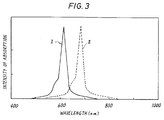
- the absorption spectra of the sub-layers 13, 14 after conversion into the J-aggregates are shown in Fig. 3 as curves I and II, respectively. As will be seen from the figure, the spectra are shifted to a longer wavelength side by about 35 to 50 nm with half-value widths as sharp as about 30 nm. From this fact, the formation of the J-aggregates is confirmed.
- the optical recording medium is initialized.
- the laser device While tracking, the laser device is set at output power of 500 mJ/cm2 and the medium is irradiated with a spot of the laser beam. By the irradiation, the sub-layer 13 alone is bleached on the spot and thus recorded. Moreover, when the optical recording medium 1 is irradiated with the laser device 5 alone at the same output level, the sub-layer 14 alone is bleached on a portion or spot where irradiated. In this manner, two bits can be independently written in one spot.
- the written spots are higher in the intensity of transmitted light than the other portions, from which information can be read out.
- the information signals of the the sub-layers 13, 14 can be independently and simultaneously read out by the sensors 6,7.
- the information of the written optical recording medium can be erased by repeating the initialization procedure (a). Information can be again written in the medium 1 by repetition of the procedure (b).
- the initialized state is determined as a colored state, and the color is bleached on writing, but the colorless state may be regarded as the initialized state and turned into a colored state by writing.
- a solution of 5 wt% of compound (I) in toluene was spin coated at 500 r.p.m. on such a substrate as used in Example 1 to form the sub-layer 13.
- the sub-layer 14 was further formed the sub-layer 14 by spin coating a solution of 5 wt% of compound (II) in toluene.
- the resultant optical recording medium could be used in the same manner as in Example 1, i.e. two bit signals per spot could be written, read, and erased.
Landscapes
- Engineering & Computer Science (AREA)
- Manufacturing & Machinery (AREA)
- Optical Record Carriers And Manufacture Thereof (AREA)
- Non-Silver Salt Photosensitive Materials And Non-Silver Salt Photography (AREA)
Description
- This invention relates to optical high density recording mediums according to the preamble of
claim 1. The invention also relates to a method for making such mediums as mentioned above and to a method for recording optical information in the recording mediums. - The optical recording mediums of the above type may be broadly classified into two groups, one group being a rewritable medium and the other group being a write-once medium. A typical rewritable optical recording medium comprises an optically transparent disc substrate and a recording layer of a photochromic dye formed on the substrate. For information recording, while the optical recording medium is being rotated for tracking, a laser beam having a wavelength of λ1 in spotted on one point of the disc surface. The photochromic dye on the spot undergoes the photochromic reaction and thus, the colorless dye on the spot is colored as having a visible absorption spectrum at λ2. By this, single bit information is recorded on the spot. On reading, a weak laser beam having a wavelength of λ2 is applied to the disc surface. The absorption of the beam in the colored portion can be detected from a change in intensity of transmitted light. On the other hand, when an intense laser beam having a wavelength of λ2 is applied to the colored portion in the same manner as in the writing operation, the photochromic dye in the portion is turned colorless and thus the information can be erased.
- If dyes having no photochromic properties are used as the recording layer, and the erasing operation is omitted from the above procedure for the photochromic dye medium, write-once optical recording is effected. However, in view of the principle of the known systems, only one bit is recorded by application of one spot of a laser beam. This places a limitation on the increase of a recording density.
- JP-A-59-152 528 which is reflected in the preamble of
claim 1 relates to a heat mode process using a rewritable optical recording medium comprising an optically transparent substrate and a recording layer formed on said substrate and comprising at least two dyes which are formed as separate sub-layers of the said recording layer, the at least two dyes having different absorption spectrum ranges optically distinguishable from each other. According to this heat mode process pits are formed in the respective layers by laser beams with inherent wavelength. - JP-A 59-223 957 relates to an optical information recording medium which is used for a process wherein information is recorded in the form of irregularities by means of a laser beam and is reproduced from variations of the reflected light. To provide a high S/N ratio and resolving power and to improve shelf life an aggregate of an organic dye - so called J-aggregate - is incorporated as at least a part of the constituting components of the recording layer. The dyes used are cyanine dyes which undergo decomposition by application of light and heat finally leading to information recording in the form of irregularities.
- The document "Thin solid Films" [133, 21 - 28 (1985)] describes the preparation of J-aggregates of photochromic spiropyrans in Langmuir-Blodgett films. Specifically the use of two spiropyrans (so called SP 16 and SP 1822) is disclosed.
- It is the object of the present invention to provide a rewritable optical recording medium and a method for recording optical information on said medium which shows improved properties, in particular an increased sensitivity together with decreased background reflections leading to a further increase of the S/N ratio.
- According to the invention this object is achieved by an recording medium according to
claim 1 and the method according to claim 4. The invention is advantageously developed by the measures mentioned in the subclaims. - The recording layer is preferably formed on the substate by a method in which a solution or solutions of a plurality of dyes are coated onto the substrate while permitting the solution to be fluidized in a direction parallel to the substrate surface such as by spin coating. Alternatively, the recording layer may be formed by the Langmuir-Blodgett film method (hereinafter referred to simply as LB film method). The resultant recording layer is heated to a temperature sufficient to allow the respective dyes to form aggregates without causing the change of the molecular structure of the dyes. As a matter of course, the temperature depends on the type of dye. The formation of the J-aggregate is advantageous in that the aggregate has a narrower absorption spectrum range than the dye used, thus enabling one to make a recording layer or layers of higher sensitivity in response to laser beams having different wavelengths by using different types of dye aggregates. When light sources and photosensors are utilized corresponding to the respective aggregates having inherent absorption spectra, a plurality of bit signals can be written in one spot of laser beams having different wavelengths corresponding to the respective aggregates.
- For recording of optical information, the optical recording medium having an optical transparent substrate and a layer of at least two dyes capable of forming corresponding aggregates and formed as separate sub-layers is irradiated with an UV ray to form photomerocyanines of the at least two dyes, then heated to a temperature sufficient to cause the respective photomerocyanines to form aggregates, and subjecting the resultant medium to optical information recording.
- Fig. 1 is a schematic view, partially in section, illustrating a principle of a recording apparatus using an optical recording medium of the invention;
- Fig. 2 is an absorption spectrum chart of a double-layer recording film of an optical recording medium obtained in Example 1 prior to formation of aggregates of the respective dyes in the layer;
- Fig. 3 is an absorption spectrum chart of the recording layer of Fig. 2 after formation of the aggregates of the respective dyes; and
- The dyes capable of forming J-aggregates include photochromic dyes. Typical photochromic dyes include spiropyrans, azobenzenes, fulgides, indigoes, thioindigioes, triarylmethanes and the like. All these dyes do not form the aggregates but have the possibility of forming J-aggregates if properly substituted or under proper treating conditions. In the practice of the invention, as photochromic dyes capable of forming J-aggregates the spiropyrans of the following general formula are used because of the good formation of J-aggregates

in which R₁ and R₂ independently represent an alkyl group having from 1 to 5 carbon atoms or an aromatic group, R₃ represents an alkyl group having at least 10 carbon atoms and preferably up to 30 carbon atoms, X is a single bond or a group selected from the following formulas
-CnH2nOCO-, -CnH2nCOO-, -CnH2nNHCO-, -CnH2nCONH-, and - CnH2nO-, wherein n ≧ 0, R₄ represents an alkyl group having from 1 to 30 carbon atoms. - In the above formula, R₁ and R₂ are each preferably methyl, ethyl, propyl and the like, or phenyl. Likewise, R₃ is preferably decyl, undecyl or the like. X is preferably - CH₂OCO- or -O-.
- Examples of typical spiropyrans include 6-nitro-1'-octadecyl-8-docosanoyloxy-3',3'-dimethylspiro[2H-1-benzothiopyran-2,2'-indoline], and the like . Needless to say, these spiropyrans are used in combination of at least two compounds.
- Spiropyrans are generally colorless but upon irradiation of UV rays, they are converted by photoisomerization into purple photomerocyanines having maximal absorption leaks at approximately 400 to 700 nm. In turn, when visible light is irradiated on the photomerocyanine, it is reversibly converted into a corresponding spiropyran. However, photomerocyanines are unstable in nature and are naturally faded in color even in the dark, thereby forming original spiropyrans. It has been found that when spiropyrans which are able to form J-aggregates are formed as a layer and subjected to UV irradiation to form corresponding photomerocyanines, the photomerocyanines can be converted into more stable J-aggregates by thermal reaction. In addition, the J-aggregate is found to have a significantly narrower absorption spectrum range than an original dye. The spiropyrans defined by the general formula may be used in combination by proper selection in consideration of absorption spectra. Typical and, in fact, preferable combinations of spiropyrans include 6-nitro-1'-octadecyl-8-docosanoyloxy-3',3'-dimethylspiro[2H-1-benzothiopyran-2,2'-indoline] capable of conversion to an aggregate predominantly absorbing light of 653 nm. It should be noted that dyes which are used in combination should preferably have absorption peaks, which are separate from each other at least by a wavelength value corresponding to the half-value width (whichever larger) or at least about 20 to 30 nm, when converted into corresponding aggregates.
- The dyes useful in the practice of the invention are formed as a recording layer or layers by a variety of methods. Such methods include, for example, an LB film method, or methods in which a solvent used is fluidized in a direction horizontal to the surface of a substrate, e.g. a spin coating method, an air doctor coating method, a blade coating method, a rod coating method a knife coating method and a squeeze coating method. Of these, the LB film method or the spin coating method is preferably used because of the good film properties. In these methods, spiropyrans or the like dyes are dissolved in inert solvents such as chloroform, aromatic hydrocarbons, e.g. benzene, toluene and the like, tetrahydrofuran, acetonitrile, acetone, ethanol and the like. A plurality of dyes is separately dissolved in the respective solvents and applied onto a substrate one by one. The dyes are each dissolved in a solvent at a concentration of 0.1 to 50 wt% of the solution.
- In the spin coating method, a 5 to 15wt% dye solution is applied onto an optically transparent substrate, such as glass, quartz or synthetic resins including polystyrene, which is preferably surface treated with an alkylsilanes, such as trimethylchlorosilane, in order to render the surface hydrophobic, followed by spinning first at 50 to 600 r.p.m. for 10 to 100 seconds and then at 1000 to 2000 r.p.m. for 100 to 300 seconds for drying, thereby forming a dye layer.
- The LB film method may be effected as follows: a solution of a dye in a suitable solvent is dropped over a water surface of an LB film-forming apparatus under conditions of water of a pH of 3 to 11 and a temperature of 10 to 30oC. Thereafter, the solution is compressed by means of a moving metal bar to such an extent of a surface pressure of 0 to 80 dynes/cm. This film is applied onto a surface-treated substrate. The above procedure is repeated to form a multilayer film on the substrate to a desired thickness of 0.0025 to 0.25 »m.
- In these method, the dyes are preferably used in combination with an aid such as a semi-solid or solid alkane, in order to form a uniform dye layer or stabilize the layer. The alkane aid may be n-octadecane or n-hexadecane and is used at a molar ratio, to the dye, of 1:3 to 3:1.
- The recording layer or layers are then subjected to UV irradiation to convert the dye or dyes into a corresponding photomerocyanines. Thereafter, the photomerocyanine layer is heated to a temperature of 30 to 45oC for 0.1 to 20 minutes although these temperature and time conditions may vary depending on the type of dye. As a result, J-aggregates of the photomerocyanines are formed. As described before, the LB film method and the spin coating method are preferred for the formation of the J-aggregate. The reason for this is not clearly known, but it is considered that these methods are effective in orientation of dye molecules in the recording layer. This oriented state of dye molecules may be called 'preaggregate'. It will be noted that the heating should be effected to such an extent that the molecular structure of a dye does not undergo an irreversible change. In this sense, exact heating conditions should be determined on the respective dyes.
- When the respective dyes are formed into separate layers, each layer should preferably have a thickness of from 0.2 to 2 »m.
- For ensuring good optical reading and writing operations, absorption spectra of different types of dye aggregates should preferably have a difference in half-value width of at least about 30 nm as indicated before.
- The optically transparent substrates used in the present invention may take any forms of a disc, plate, sheet or the like and are generally made of glass, quartz, synthetic resins such as polystyrene, polyacrylates and the like.
- The present invention is more particularly described by way of examples.
- In this example, spiropyrans of the following chemical formulae (I) and (II) were used to make an optical recording medium by the LB film method.


A Langmuir-type LB film-forming apparatus having a 1000 mm x 500 mm trough was provided, in which a subphase of an aqueous phosphate buffer solution adjusted to a pH of 7.2 and a temperature of 18oC was filled. One mmol/l of compound (I) and 2 mmol/l of n-octadecane were dissolved in chloroform. Seven hundreds microliters of the chloroform solution was developed over the surface of the subphase to form a monomolecular film. The film pressure was automatically controlled to be 20 mN/m. A glass disc having a diameter of 3.5 inches was provided as a substrate. The substrate was rendered hydrophobic on the surface thereof by immersion in a 10 vol% trimethylchlorosilane solution in toluene for 30 minutes. This substrate was vertically moved toward the monomolecular film of the compound (I) to form on LB film (20 layers of Y film) on the substrate as a layer. - The above procedure was repeated using compound (II) and n-octadecane, thereby forming another layer on the first-mentioned layer.
- The thus fabricated double-layer recording medium is optically recorded and reproduced by an optical recording system as schematically shown in Fig. 1. In the figure, there is shown in
optical recording medium 1 which has aglass substrate 11 and arecording layer 12 consisting of a sub-layer 13 of compound (I) and a sub-layer 14 of compound (II). Indicated by 2 is a lamp for erasure capable of emitting a UV ray of 350 nm and by 3 is an IR lamp for formation of aggregates of compounds (I) and (II). In front of therecording layer 12, there are provided laser devices 4, 5 capable of emitting two laser beams of 618 nm and 653 nm. These laser devices 4,5 are suitably arranged to give one optical axis and are able to emit the laser beams while carrying out tracking of the medium. The laser devices 4,5 are capable of changing output power from 500 mJ/cm² to 50 mJ/cm². Lasers used in the invention may be CO₂ laser, Xe laser, dye lasers or the like. Indicated by 6,7 are reading sensors having optical filters therein and capable of sensing light rays of 618 and 653 nm, respectively. Thesensors 6,7 detect the intensities of beams from the laser devices 4, 5 passed through theoptical recording medium 1. - Recording of the medium is described.
- The recording layer obtained just after the fabrication is colorless. The
medium 1 is exposed over the entire surface thereof with light from theerasure lamp 2, for example, for 10 minutes. As a result, colored photomerocyanines are formed in therespective sub-layers medium 1 and therecording layer 11 is maintained at a temperature of 35 to 40oC for about 15 minutes, with the result that the photomerocyanines in the recording layer are converted into J-aggregates with different colors. The absorption spectra of the sub-layers 13, 14 after conversion into the J-aggregates are shown in Fig. 3 as curves I and II, respectively. As will be seen from the figure, the spectra are shifted to a longer wavelength side by about 35 to 50 nm with half-value widths as sharp as about 30 nm. From this fact, the formation of the J-aggregates is confirmed. By the above procedure, the optical recording medium is initialized. - While tracking, the laser device is set at output power of 500 mJ/cm² and the medium is irradiated with a spot of the laser beam. By the irradiation, the sub-layer 13 alone is bleached on the spot and thus recorded. Moreover, when the
optical recording medium 1 is irradiated with the laser device 5 alone at the same output level, the sub-layer 14 alone is bleached on a portion or spot where irradiated. In this manner, two bits can be independently written in one spot. - While tracking in the same manner as in the writing operation, laser beams from the laser devices 4,5 set at 5 mJ/cm² are simultaneously irradiated on the
medium 1 and the intensities of the transmitted beams are detected by thesensors 6, 7. The written spots are higher in the intensity of transmitted light than the other portions, from which information can be read out. The information signals of the the sub-layers 13, 14 can be independently and simultaneously read out by thesensors 6,7. - The information of the written optical recording medium can be erased by repeating the initialization procedure (a). Information can be again written in the
medium 1 by repetition of the procedure (b). - In the above procedure, the initialized state is determined as a colored state, and the color is bleached on writing, but the colorless state may be regarded as the initialized state and turned into a colored state by writing.
- A solution of 5 wt% of compound (I) in toluene was spin coated at 500 r.p.m. on such a substrate as used in Example 1 to form the sub-layer 13. On the sub-layer 13 was further formed the sub-layer 14 by spin coating a solution of 5 wt% of compound (II) in toluene. The resultant optical recording medium could be used in the same manner as in Example 1, i.e. two bit signals per spot could be written, read, and erased.
Claims (5)
- A rewritable optical recording medium comprising: an optically transparent substrate and a recording layer formed on said substrate and comprising at least two dyes which are formed as separate sub-layers of the said recording layer, the said at least two dyes having different absorption spectrum ranges optically distinguishable from each other characterized in that the at least two dyes are J-aggregates of photochromic spiropyran dyes having the general formula
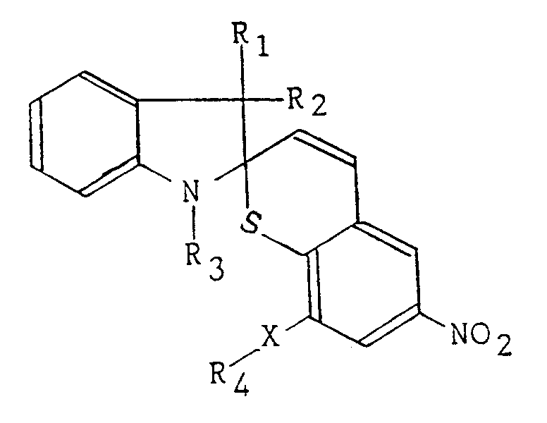
-Cn H2n OCO-, -Cn H2n COO-, -Cn H2n NHCO-, -Cn H2n CONH-, and -Cn H2n O-, wherein n ≧ 0, R₄ represents an alkyl group having from 1 to 30 carbon atoms and
each of the dyes being capable of undergoing a color change on irradiation of a laser beam having a wavelength inherent to the respecitve J-aggregate. - An optical recording medium according to claim 1, wherein the spiropyran dye is used in combination with a semi-solid or solid alkane.
- An optical recording medium according to claim 1, wherein said photochromic spiropyrane dyes are dissolved in a solvent to form corresponding J-aggregates and gelled.
- A method for recording optical information on an optical recording medium according to anyone of claims 1 to 3, which comprises forming solutions of the respective dyes, applying the respective solutions as separate sub-layers to form a recording layer, irradiating the layer with an UV ray to form photomerocyanines of the at least two dyes, heating the layer to a temperature sufficient to cause the respective photomerocyanines to form aggregates, and subjecting the resultant medium to optical information recording.
- A method according to claim 4, further comprising heating the recorded medium to erase the optical information.
Applications Claiming Priority (10)
| Application Number | Priority Date | Filing Date | Title |
|---|---|---|---|
| JP44061/85 | 1985-03-06 | ||
| JP60044061A JPS61203450A (en) | 1985-03-06 | 1985-03-06 | optical recording medium |
| JP47197/85 | 1985-03-08 | ||
| JP60047197A JPS61205187A (en) | 1985-03-08 | 1985-03-08 | Photo-recording medium and method |
| JP231519/85 | 1985-10-17 | ||
| JP60231517A JPS6290651A (en) | 1985-10-17 | 1985-10-17 | Recording method on optical recording media |
| JP60231519A JPS6290649A (en) | 1985-10-17 | 1985-10-17 | optical recording medium |
| JP231517/85 | 1985-10-17 | ||
| JP60231518A JPS6292146A (en) | 1985-10-17 | 1985-10-17 | Manufacturing method for optical recording media |
| JP231518/85 | 1985-10-17 |
Publications (3)
| Publication Number | Publication Date |
|---|---|
| EP0193931A2 EP0193931A2 (en) | 1986-09-10 |
| EP0193931A3 EP0193931A3 (en) | 1988-06-29 |
| EP0193931B1 true EP0193931B1 (en) | 1994-06-08 |
Family
ID=27522361
Family Applications (1)
| Application Number | Title | Priority Date | Filing Date |
|---|---|---|---|
| EP86102848A Expired - Lifetime EP0193931B1 (en) | 1985-03-06 | 1986-03-05 | Optical high density recording mediums, method for making same and method for recording optical information in the medium |
Country Status (3)
| Country | Link |
|---|---|
| US (2) | US4737427A (en) |
| EP (1) | EP0193931B1 (en) |
| DE (1) | DE3689891T2 (en) |
Families Citing this family (36)
| Publication number | Priority date | Publication date | Assignee | Title |
|---|---|---|---|---|
| US4933221A (en) * | 1984-07-31 | 1990-06-12 | Canon Kabushiki Kaisha | Optical recording device |
| DE3689891T2 (en) * | 1985-03-06 | 1994-10-20 | Matsushita Electric Ind Co Ltd | High density optical recording media, methods of making the same and methods for recording optical information in this medium. |
| EP0218263B1 (en) * | 1985-10-11 | 1992-05-27 | Sony Corporation | Laser information recording medium having an improved recording layer |
| GB8714202D0 (en) * | 1987-06-17 | 1987-07-22 | Plessey Co Plc | Contrast enthancement in optical data storage |
| GB8717619D0 (en) * | 1987-07-24 | 1987-09-03 | Plessey Co Plc | Reversible infra-red recording medium |
| EP0312339A3 (en) * | 1987-10-13 | 1990-05-23 | Mitsui Petrochemical Industries, Ltd. | Optical information recording media and optical recording systems |
| JPH0246538A (en) * | 1988-08-05 | 1990-02-15 | Sharp Corp | Optical memory element |
| US5079061A (en) * | 1989-02-27 | 1992-01-07 | Matsushita Electric Industrial Co., Ltd. | Optical storage media |
| JP2910089B2 (en) * | 1989-09-29 | 1999-06-23 | 松下電器産業株式会社 | Optical recording medium detection method |
| DE69028908T2 (en) * | 1989-12-28 | 1997-05-07 | Sanyo Electric Co | Recording and playback processes |
| FR2656722A1 (en) * | 1989-12-29 | 1991-07-05 | Thomson Csf | THERMO-OPTICALLY INSCRIABLE OPTICAL RECORDING MEDIUM, METHOD OF MAKING SUCH MEDIUM, AND INFORMATION CARRIER USING THE SAME |
| JP2801739B2 (en) * | 1990-05-15 | 1998-09-21 | パイオニア株式会社 | Recording / reproducing method of multilayer recording film |
| JPH0798934B2 (en) * | 1990-10-05 | 1995-10-25 | 松下電器産業株式会社 | Photochromic material and optical recording medium |
| JP2842939B2 (en) * | 1990-10-15 | 1999-01-06 | パイオニア株式会社 | Optical recording medium |
| JP2975761B2 (en) * | 1991-03-04 | 1999-11-10 | 松下電器産業株式会社 | Optical recording medium using photochromic material and its composition |
| JP2552036B2 (en) * | 1991-03-14 | 1996-11-06 | 松下電器産業株式会社 | WDM optical recording medium and recording, erasing and reproducing method using the same |
| US5399451A (en) * | 1991-03-14 | 1995-03-21 | Matsushita Electric Industrial Co., Ltd. | Optical recording medium and method for using the same |
| US5586107A (en) * | 1991-06-04 | 1996-12-17 | International Business Machines Corporation | Multiple data surface optical data storage system |
| US5666344A (en) * | 1991-06-04 | 1997-09-09 | International Business Machines Corporation | Multiple data surface optical data storage system |
| US5202875A (en) * | 1991-06-04 | 1993-04-13 | International Business Machines Corporation | Multiple data surface optical data storage system |
| US5255262A (en) * | 1991-06-04 | 1993-10-19 | International Business Machines Corporation | Multiple data surface optical data storage system with transmissive data surfaces |
| TW218427B (en) * | 1991-06-04 | 1994-01-01 | Ibm | |
| MY138253A (en) * | 1991-06-04 | 2009-05-29 | Mitsubishi Electric Corp | Multiple data surface data storage system and method |
| US5449590A (en) * | 1991-06-04 | 1995-09-12 | International Business Machines Corporation | Multiple data surface optical data storage system |
| US5719850A (en) * | 1991-10-03 | 1998-02-17 | Olympus Optical Co., Ltd. | Optical storage medium with first layer containing optically readable information overlying second layer containing visible information |
| JPH06325414A (en) * | 1993-05-17 | 1994-11-25 | Pioneer Electron Corp | Method for controlling reflectance |
| US5644555A (en) * | 1995-01-19 | 1997-07-01 | International Business Machines Corporation | Multiple data surface magneto-optical data storage system |
| US6479214B1 (en) * | 1995-01-31 | 2002-11-12 | Shelly Albaum | High density optical storage and retrieval using the electromagnetic absorption spectrum to represent multiple bit information |
| NO301144B1 (en) * | 1995-05-23 | 1997-09-15 | Opticom As | Optical data storage |
| US5834122A (en) * | 1996-11-25 | 1998-11-10 | Hoechst Celanese Corp. | Spectrally tuned multiple bandpass filters for video displays |
| WO2001004702A1 (en) * | 1999-07-08 | 2001-01-18 | Kromotek Ltd | Dry photographic printing process |
| EP1118988B1 (en) * | 1999-07-12 | 2009-07-01 | Panasonic Corporation | Optical information recording medium and method for initializing the same |
| JP2004338091A (en) * | 2001-02-20 | 2004-12-02 | Kansai Tlo Kk | Recording method using coloring matter |
| US8076058B2 (en) * | 2004-09-30 | 2011-12-13 | Hewlett-Packard Development Company, L.P. | Color forming compositions and associated methods |
| JP2008012884A (en) * | 2006-07-10 | 2008-01-24 | Taiyo Yuden Co Ltd | Optical information recording medium and its manufacturing method |
| US20090097898A1 (en) * | 2007-10-16 | 2009-04-16 | Xerox Corporation | Hand held photochromic marking implement |
Family Cites Families (11)
| Publication number | Priority date | Publication date | Assignee | Title |
|---|---|---|---|---|
| BE566862A (en) * | 1957-04-23 | |||
| US3980480A (en) * | 1970-09-01 | 1976-09-14 | Urbain Leopold Laridon | Photographic recording and reproduction of information photochromic composition containing polyhalogenated hydrocarbon, spiropyran compound and heterocyclic mercapto compound and the use thereof |
| GB1359472A (en) * | 1970-09-01 | 1974-07-10 | Agfa Gevaert | Photographic recording and reproduction of information |
| US3989530A (en) * | 1974-03-19 | 1976-11-02 | Robillard Jean J A | Process for recording phase holograms using energy-activated sensitizer |
| DE2433373A1 (en) * | 1974-07-11 | 1976-01-29 | Agfa Gevaert Ag | LIGHT SENSITIVE MATERIAL |
| US4270130A (en) * | 1979-01-08 | 1981-05-26 | Eastman Kodak Company | Thermal deformation record device with bleachable dye |
| JPS5856239A (en) * | 1981-09-28 | 1983-04-02 | Tdk Corp | Optical recording medium |
| JPS59223957A (en) * | 1983-06-02 | 1984-12-15 | Ricoh Co Ltd | Optical information recording medium |
| US4513071A (en) * | 1983-11-21 | 1985-04-23 | Eastman Kodak Company | Erasable information recording process using co-crystalline dye complexes |
| DE3689891T2 (en) * | 1985-03-06 | 1994-10-20 | Matsushita Electric Ind Co Ltd | High density optical recording media, methods of making the same and methods for recording optical information in this medium. |
| GB8507690D0 (en) * | 1985-03-25 | 1985-05-01 | Ici Plc | Infra-red patterns |
-
1986
- 1986-03-05 DE DE3689891T patent/DE3689891T2/en not_active Expired - Lifetime
- 1986-03-05 EP EP86102848A patent/EP0193931B1/en not_active Expired - Lifetime
- 1986-03-05 US US06/836,625 patent/US4737427A/en not_active Expired - Lifetime
-
1988
- 1988-01-14 US US07/145,686 patent/US4845021A/en not_active Expired - Lifetime
Non-Patent Citations (1)
| Title |
|---|
| PATENT ABSTRACTS OF JAPAN, vol. 9, no. 2, (P-325)(1725), 8 January 1985 * |
Also Published As
| Publication number | Publication date |
|---|---|
| EP0193931A2 (en) | 1986-09-10 |
| US4737427A (en) | 1988-04-12 |
| US4845021A (en) | 1989-07-04 |
| EP0193931A3 (en) | 1988-06-29 |
| DE3689891D1 (en) | 1994-07-14 |
| DE3689891T2 (en) | 1994-10-20 |
Similar Documents
| Publication | Publication Date | Title |
|---|---|---|
| US4737427A (en) | Optical high density recording mediums, method for making same and method for recording optical information in the medium | |
| US5399451A (en) | Optical recording medium and method for using the same | |
| US4794068A (en) | Optical recording medium | |
| EP0218263B1 (en) | Laser information recording medium having an improved recording layer | |
| US4678736A (en) | Optical recording media on which information is stored and method of making same | |
| EP0182594B1 (en) | Optical recording elements comprising telluropyrylium dyes | |
| US5576084A (en) | Optical recording medium and the producing method of the optical recording medium | |
| Matsui et al. | Application of Photochromic S-Dimethylaminoindolylfulgide to Photon-Mode Erasable Optical Memory Media with Non-Destructive Readout Ability Based on Wavelength Dependence of Bleaching Quantum Yield. | |
| US5196227A (en) | Method for making optical recording mediums | |
| EP0230024B1 (en) | Optical recording medium having a stabilized recording layer | |
| US4446223A (en) | Recording and information record elements comprising oxoindolizine and oxoindolizinium dyes | |
| EP0503428B1 (en) | Optical recording medium and method for using the same | |
| US5316899A (en) | Optical recording medium | |
| US5117416A (en) | Recording method for multi-layer recording film | |
| US5252371A (en) | Rewritable photochromic optical disk | |
| KR920006313B1 (en) | Optical information recording medium and optical recording method | |
| JP2890760B2 (en) | Optical recording medium | |
| JPH0276126A (en) | Method for detecting recording status of optical recording medium | |
| JPH0367251B2 (en) | ||
| JPS61116353A (en) | Dye film | |
| JPS62147454A (en) | optical recording medium | |
| JPS62147455A (en) | optical recording medium | |
| JP2695264B2 (en) | Optical recording and reading method | |
| JPH0443571B2 (en) | ||
| JPH07302438A (en) | Optical information recording medium and its production |
Legal Events
| Date | Code | Title | Description |
|---|---|---|---|
| PUAI | Public reference made under article 153(3) epc to a published international application that has entered the european phase |
Free format text: ORIGINAL CODE: 0009012 |
|
| AK | Designated contracting states |
Kind code of ref document: A2 Designated state(s): DE FR GB |
|
| PUAL | Search report despatched |
Free format text: ORIGINAL CODE: 0009013 |
|
| AK | Designated contracting states |
Kind code of ref document: A3 Designated state(s): DE FR GB |
|
| 17P | Request for examination filed |
Effective date: 19880830 |
|
| 17Q | First examination report despatched |
Effective date: 19900301 |
|
| GRAA | (expected) grant |
Free format text: ORIGINAL CODE: 0009210 |
|
| AK | Designated contracting states |
Kind code of ref document: B1 Designated state(s): DE FR GB |
|
| REF | Corresponds to: |
Ref document number: 3689891 Country of ref document: DE Date of ref document: 19940714 |
|
| ET | Fr: translation filed | ||
| PLBE | No opposition filed within time limit |
Free format text: ORIGINAL CODE: 0009261 |
|
| STAA | Information on the status of an ep patent application or granted ep patent |
Free format text: STATUS: NO OPPOSITION FILED WITHIN TIME LIMIT |
|
| 26N | No opposition filed | ||
| REG | Reference to a national code |
Ref country code: GB Ref legal event code: IF02 |
|
| REG | Reference to a national code |
Ref country code: GB Ref legal event code: 746 Effective date: 20031002 |
|
| REG | Reference to a national code |
Ref country code: FR Ref legal event code: D6 |
|
| PGFP | Annual fee paid to national office [announced via postgrant information from national office to epo] |
Ref country code: GB Payment date: 20050302 Year of fee payment: 20 |
|
| PGFP | Annual fee paid to national office [announced via postgrant information from national office to epo] |
Ref country code: DE Payment date: 20050304 Year of fee payment: 20 |
|
| PGFP | Annual fee paid to national office [announced via postgrant information from national office to epo] |
Ref country code: FR Payment date: 20050308 Year of fee payment: 20 |
|
| PG25 | Lapsed in a contracting state [announced via postgrant information from national office to epo] |
Ref country code: GB Free format text: LAPSE BECAUSE OF EXPIRATION OF PROTECTION Effective date: 20060304 |
|
| REG | Reference to a national code |
Ref country code: GB Ref legal event code: PE20 |