EP0193631A1 - Device for dissipating heat, particularly, in motor vehicle headlights, searchlights, and the like - Google Patents
Device for dissipating heat, particularly, in motor vehicle headlights, searchlights, and the like Download PDFInfo
- Publication number
- EP0193631A1 EP0193631A1 EP85102432A EP85102432A EP0193631A1 EP 0193631 A1 EP0193631 A1 EP 0193631A1 EP 85102432 A EP85102432 A EP 85102432A EP 85102432 A EP85102432 A EP 85102432A EP 0193631 A1 EP0193631 A1 EP 0193631A1
- Authority
- EP
- European Patent Office
- Prior art keywords
- motor vehicle
- searchlights
- parabolic reflector
- dissipating heat
- vehicle headlights
- Prior art date
- Legal status (The legal status is an assumption and is not a legal conclusion. Google has not performed a legal analysis and makes no representation as to the accuracy of the status listed.)
- Withdrawn
Links
- 239000004020 conductor Substances 0.000 claims abstract description 7
- 239000004033 plastic Substances 0.000 claims description 5
- 229920003023 plastic Polymers 0.000 claims description 5
- 239000000463 material Substances 0.000 claims description 3
- 229910000831 Steel Inorganic materials 0.000 description 2
- 238000004519 manufacturing process Methods 0.000 description 2
- 230000001681 protective effect Effects 0.000 description 2
- 239000010959 steel Substances 0.000 description 2
- 239000011248 coating agent Substances 0.000 description 1
- 238000000576 coating method Methods 0.000 description 1
- 239000011521 glass Substances 0.000 description 1
- 239000002184 metal Substances 0.000 description 1
- 239000007769 metal material Substances 0.000 description 1
- XLYOFNOQVPJJNP-UHFFFAOYSA-N water Substances O XLYOFNOQVPJJNP-UHFFFAOYSA-N 0.000 description 1
Images

Classifications
-
- F—MECHANICAL ENGINEERING; LIGHTING; HEATING; WEAPONS; BLASTING
- F21—LIGHTING
- F21S—NON-PORTABLE LIGHTING DEVICES; SYSTEMS THEREOF; VEHICLE LIGHTING DEVICES SPECIALLY ADAPTED FOR VEHICLE EXTERIORS
- F21S45/00—Arrangements within vehicle lighting devices specially adapted for vehicle exteriors, for purposes other than emission or distribution of light
- F21S45/40—Cooling of lighting devices
- F21S45/47—Passive cooling, e.g. using fins, thermal conductive elements or openings
- F21S45/48—Passive cooling, e.g. using fins, thermal conductive elements or openings with means for conducting heat from the inside to the outside of the lighting devices, e.g. with fins on the outer surface of the lighting device
-
- F—MECHANICAL ENGINEERING; LIGHTING; HEATING; WEAPONS; BLASTING
- F21—LIGHTING
- F21S—NON-PORTABLE LIGHTING DEVICES; SYSTEMS THEREOF; VEHICLE LIGHTING DEVICES SPECIALLY ADAPTED FOR VEHICLE EXTERIORS
- F21S41/00—Illuminating devices specially adapted for vehicle exteriors, e.g. headlamps
- F21S41/10—Illuminating devices specially adapted for vehicle exteriors, e.g. headlamps characterised by the light source
- F21S41/19—Attachment of light sources or lamp holders
- F21S41/192—Details of lamp holders, terminals or connectors
-
- F—MECHANICAL ENGINEERING; LIGHTING; HEATING; WEAPONS; BLASTING
- F21—LIGHTING
- F21S—NON-PORTABLE LIGHTING DEVICES; SYSTEMS THEREOF; VEHICLE LIGHTING DEVICES SPECIALLY ADAPTED FOR VEHICLE EXTERIORS
- F21S45/00—Arrangements within vehicle lighting devices specially adapted for vehicle exteriors, for purposes other than emission or distribution of light
- F21S45/40—Cooling of lighting devices
-
- F—MECHANICAL ENGINEERING; LIGHTING; HEATING; WEAPONS; BLASTING
- F21—LIGHTING
- F21S—NON-PORTABLE LIGHTING DEVICES; SYSTEMS THEREOF; VEHICLE LIGHTING DEVICES SPECIALLY ADAPTED FOR VEHICLE EXTERIORS
- F21S45/00—Arrangements within vehicle lighting devices specially adapted for vehicle exteriors, for purposes other than emission or distribution of light
- F21S45/40—Cooling of lighting devices
- F21S45/49—Attachment of the cooling means
-
- F—MECHANICAL ENGINEERING; LIGHTING; HEATING; WEAPONS; BLASTING
- F21—LIGHTING
- F21S—NON-PORTABLE LIGHTING DEVICES; SYSTEMS THEREOF; VEHICLE LIGHTING DEVICES SPECIALLY ADAPTED FOR VEHICLE EXTERIORS
- F21S41/00—Illuminating devices specially adapted for vehicle exteriors, e.g. headlamps
- F21S41/10—Illuminating devices specially adapted for vehicle exteriors, e.g. headlamps characterised by the light source
- F21S41/14—Illuminating devices specially adapted for vehicle exteriors, e.g. headlamps characterised by the light source characterised by the type of light source
- F21S41/162—Incandescent light sources, e.g. filament or halogen lamps
- F21S41/168—Incandescent light sources, e.g. filament or halogen lamps having a filament arranged transversally to the optical axis of the illuminating device
-
- F—MECHANICAL ENGINEERING; LIGHTING; HEATING; WEAPONS; BLASTING
- F21—LIGHTING
- F21S—NON-PORTABLE LIGHTING DEVICES; SYSTEMS THEREOF; VEHICLE LIGHTING DEVICES SPECIALLY ADAPTED FOR VEHICLE EXTERIORS
- F21S45/00—Arrangements within vehicle lighting devices specially adapted for vehicle exteriors, for purposes other than emission or distribution of light
- F21S45/30—Ventilation or drainage of lighting devices
- F21S45/33—Ventilation or drainage of lighting devices specially adapted for headlamps
-
- F—MECHANICAL ENGINEERING; LIGHTING; HEATING; WEAPONS; BLASTING
- F21—LIGHTING
- F21V—FUNCTIONAL FEATURES OR DETAILS OF LIGHTING DEVICES OR SYSTEMS THEREOF; STRUCTURAL COMBINATIONS OF LIGHTING DEVICES WITH OTHER ARTICLES, NOT OTHERWISE PROVIDED FOR
- F21V21/00—Supporting, suspending, or attaching arrangements for lighting devices; Hand grips
- F21V21/14—Adjustable mountings
- F21V21/30—Pivoted housings or frames
-
- F—MECHANICAL ENGINEERING; LIGHTING; HEATING; WEAPONS; BLASTING
- F21—LIGHTING
- F21V—FUNCTIONAL FEATURES OR DETAILS OF LIGHTING DEVICES OR SYSTEMS THEREOF; STRUCTURAL COMBINATIONS OF LIGHTING DEVICES WITH OTHER ARTICLES, NOT OTHERWISE PROVIDED FOR
- F21V29/00—Protecting lighting devices from thermal damage; Cooling or heating arrangements specially adapted for lighting devices or systems
- F21V29/50—Cooling arrangements
- F21V29/70—Cooling arrangements characterised by passive heat-dissipating elements, e.g. heat-sinks
- F21V29/71—Cooling arrangements characterised by passive heat-dissipating elements, e.g. heat-sinks using a combination of separate elements interconnected by heat-conducting means, e.g. with heat pipes or thermally conductive bars between separate heat-sink elements
Definitions
- This invention relates to a device for dissipating heat particularly in motor vehicle headlights, searchlights, and the like.
- foglights, headlights, and other comparable lighting fixtures carried on motor vehicles and having a parabolic reflector body formed from some plastic material incur the serious problem of how to dissipate the heat, generated by incandescent lamps, when lit inside the reflector body towards the outside thereof.
- the heat produced is, in some cases quite substantial and may result in deformation of a lamp holder body made of plastics.
- a conventional approach is that of installing, on the interior of the parabolic reflector body, reflective metal surfaces which practically form a protective shield against the heat for the parabolic reflector.
- This prior approach whilst providing a surface having good light reflecting properties, is less than fully satisfactory from a functional standpoint of heat. dissipation, because such a protective shield is only effective to protect the surfaces from heat generated by an incandescent lamp, lit inside the reflector body, instead of dissipating the heat to the exterior thereof, and has the additional disadvantage of increasing the manufacturing and assembling costs for the parabolic reflector.
- the aim of this invention to obviate the above problem by providing a device for dissipating heat particularly in motor vehicle headlights, foglights, and the like, which includes means for encouraging the dissipation of heat, generated by a lit incandescent lamp from the interior to the exterior of a parabolic reflector.
- a device for dissipating heat particularly in motor vehicle headlights, searchlights, and the like characterised in that it comprises, on the interior of a parabolic reflector, a lamp holder bracket made of a thermally conductive material and having at least one portion thereof in contact with at least one portion of a connection element formed from a thermally conductive material and having at least one other portion thereof, located on the exterior of said parabolic reflector, adapted for thermal conduction contact with the body of a motor vehicle or the like.
- a device for dissipating heat particularly in motor vehicle headlights, searchlights, and the like comprises a lamp holder bracket 2 located on the interior of a parabolic reflector 1 having a body 1b, formed with a mounting hole 1c and a through hole 1d, and closed at the front open end 1e thereof by a glass panel 1a and may have any suitable configuration.
- the parabolic reflector 1 includes a plastics body which is coated internally with a reflective layer 20..
- the lamp holder bracket 2 defines, in a conventional manner a substantially U -shaped configuration formed at an upper portion 2a thereof, with a yoke 3 for engagement with an incandescent lamp 4, and is formed at the bottom portion 2b thereof with a deep hollow 5 adapted to fit into a seat 6 defined in the bottom portion of the body 1b of the reflector 1 at the area where a mounting bracket 11 is located.
- the lamp holder bracket 2 which is engaged by a lamp retaining spring, indicated at 8, is formed from a thermally conductive material, such as steel or the like.
- connection element which comprises, in this case, a pin 10, including a mid portion 10b and a head 10c, at least an end part of said. pin 10 opposite to said head 10c being threaded, for engagement, with a threaded nut 10a, also being made of steel, for securing the body of the reflector 1 to a mounting bracket 11, comprising a pair of mutually parallel legs 11b, each having a through hole 11c, 11d formed therein and extending orthogonally from a plane containing a centre portion 11a formed therebetween, said mounting bracket 11 advantageously defining a U-like shape.
- the mounting bracket 11 is formed at its center portion 11a with a throughgoing hole 12 adapted for engagement by a bolt 13 for fastening to the body of the motor vehicle or the like, whilst said through holes 11c, 11d are adapted for engagement by said pin 10.
- the pin 10 and its respective locknut 10a practically form a heat bridge between the mounting bracket 11 and lamp holder bracket 2, which bridge is effective to transfer to the outside of the lamp holder most of the heat generated by the incandescent lamp 4 when lit.
- the pin 10 has its mid-portion 10b in close thermal conduction contact with the lower portion 2b of the lamp holder bracket 2, whilst its outer portion of the pin 10 - including the head 10c and the nut 10a threadedly mounted thereon - is in contact relationship with the legs 11b of the bracket 11, which is located on the exterior of the reflector body, and accordingly is effective to dissipate to the outside thereof any heat generated by the incandescent lamp 4, being assisted also by virtue of the fact that the mid-portion 11a is adapted for contacting a motor vehicle body.
- the invention achieves its objects, and in particular the fact is outstanding that without employing any added elements but merely altering and rationalising the configuration of the lamp holder bracket, the important advantage is afforded of establishing an internal to external thermal bridge, whilst introducing no risk of water or the like getting into the lamp holding body.
- the parabolic reflector no longer requires to be made of a metal material separately from the reflector body, but may be simply provided by the reflective coating, indicated at 20, on the inner surface of the reflector body 1 of plastics.
- any materials, dimensions and contingent shapes may be any selected to meet individual requirements, providing that they are compatible with the intended application.
Landscapes
- Engineering & Computer Science (AREA)
- General Engineering & Computer Science (AREA)
- Non-Portable Lighting Devices Or Systems Thereof (AREA)
- Lighting Device Outwards From Vehicle And Optical Signal (AREA)
Abstract
@ The device comprises, on the interior of a parabolic reflector (1), a lamp holder bracket (2) made of a thermally conductive material and having at least one portion (5) thereof in contact with at least one portion (10b) of a connection element (10) formed from a thermally conductive material and another portion (10a, 10c) thereof on the reflector (1) exterior which may be placed in thermal conduction contact with the body of a motor vehicle and the like.
Description
- This invention relates to a device for dissipating heat particularly in motor vehicle headlights, searchlights, and the like.
- As is known, foglights, headlights, and other comparable lighting fixtures carried on motor vehicles and having a parabolic reflector body formed from some plastic material incur the serious problem of how to dissipate the heat, generated by incandescent lamps, when lit inside the reflector body towards the outside thereof.
- In fact, the heat produced is, in some cases quite substantial and may result in deformation of a lamp holder body made of plastics.
- In an attempt to solve this problem, a conventional approach is that of installing, on the interior of the parabolic reflector body, reflective metal surfaces which practically form a protective shield against the heat for the parabolic reflector. This prior approach, whilst providing a surface having good light reflecting properties, is less than fully satisfactory from a functional standpoint of heat. dissipation, because such a protective shield is only effective to protect the surfaces from heat generated by an incandescent lamp, lit inside the reflector body, instead of dissipating the heat to the exterior thereof, and has the additional disadvantage of increasing the manufacturing and assembling costs for the parabolic reflector.
- It is,.therefore, the aim of this invention to obviate the above problem by providing a device for dissipating heat particularly in motor vehicle headlights, foglights, and the like, which includes means for encouraging the dissipation of heat, generated by a lit incandescent lamp from the interior to the exterior of a parabolic reflector.
- Within the above aim, it is a particular object of the invention to provide such a device which is simple to assemble, and, while affording greatly improved performance, requires no additional component elements over and above those which are normally comprised in a motor vehicle headlight, searchlight or the like, by adapting elements which are normally included in any such headlight or searchlight to dissipate heat.
- It is a farther object of this invention to provide such a device which is simple to manufacture and can give full assurance of being reliable and safe to use.
- The above aim, as well as these and other objects such-as will be apparent hereinafter, are achieved by a device for dissipating heat particularly in motor vehicle headlights, searchlights, and the like, according to the invention, characterised in that it comprises, on the interior of a parabolic reflector, a lamp holder bracket made of a thermally conductive material and having at least one portion thereof in contact with at least one portion of a connection element formed from a thermally conductive material and having at least one other portion thereof, located on the exterior of said parabolic reflector, adapted for thermal conduction contact with the body of a motor vehicle or the like.
- Further features and advantages will be apparent from the following detailed description of a device for dissipating heat particularly in motor vehicle headlights, searchlights, and the like, with reference to the accompanying illustrative but not limitative drawings, where:
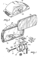
- Figure 1 is an exploded perspective view of a headlight incorporating the device of this invention;
- Figure 2 is a cross-sectional view of the headlight;
- Figure 3 is a view of the parabolic reflector body showing the exterior thereof; and
- Figure 4 is a rear view of the headlight of figure 1, in an assembled condition thereof.
- Making reference to the cited drawing figures, a device for dissipating heat particularly in motor vehicle headlights, searchlights, and the like, according to this invention, comprises a
lamp holder bracket 2 located on the interior of aparabolic reflector 1 having a body 1b, formed with a mounting hole 1c and a through hole 1d, and closed at the front open end 1e thereof by a glass panel 1a and may have any suitable configuration. Advantageously, theparabolic reflector 1 includes a plastics body which is coated internally with areflective layer 20.. - The
lamp holder bracket 2 defines, in a conventional manner a substantially U -shaped configuration formed at an upper portion 2a thereof, with a yoke 3 for engagement with an incandescent lamp 4, and is formed at the bottom portion 2b thereof with a deep hollow 5 adapted to fit into a seat 6 defined in the bottom portion of the body 1b of thereflector 1 at the area where amounting bracket 11 is located. - The
lamp holder bracket 2, which is engaged by a lamp retaining spring, indicated at 8, is formed from a thermally conductive material, such as steel or the like. - At the lower portion of the hollow 5 there engages as by contact with the hollow itself a connection element which comprises, in this case, a
pin 10, including a mid portion 10b and ahead 10c, at least an end part of said.pin 10 opposite to saidhead 10c being threaded, for engagement, with a threadednut 10a, also being made of steel, for securing the body of thereflector 1 to amounting bracket 11, comprising a pair of mutually parallel legs 11b, each having a throughhole 11c, 11d formed therein and extending orthogonally from a plane containing a centre portion 11a formed therebetween, said mountingbracket 11 advantageously defining a U-like shape. - The
mounting bracket 11 is formed at its center portion 11a with a throughgoinghole 12 adapted for engagement by abolt 13 for fastening to the body of the motor vehicle or the like, whilst said throughholes 11c, 11d are adapted for engagement by saidpin 10. - Thus, with the arrangement just discussed, the
pin 10 and itsrespective locknut 10a practically form a heat bridge between themounting bracket 11 andlamp holder bracket 2, which bridge is effective to transfer to the outside of the lamp holder most of the heat generated by the incandescent lamp 4 when lit. - In fact, the
pin 10 has its mid-portion 10b in close thermal conduction contact with the lower portion 2b of thelamp holder bracket 2, whilst its outer portion of the pin 10 - including thehead 10c and the nut 10a threadedly mounted thereon - is in contact relationship with the legs 11b of thebracket 11, which is located on the exterior of the reflector body, and accordingly is effective to dissipate to the outside thereof any heat generated by the incandescent lamp 4, being assisted also by virtue of the fact that the mid-portion 11a is adapted for contacting a motor vehicle body. - It may be appreciated from the foregoing description that the invention achieves its objects, and in particular the fact is outstanding that without employing any added elements but merely altering and rationalising the configuration of the lamp holder bracket, the important advantage is afforded of establishing an internal to external thermal bridge, whilst introducing no risk of water or the like getting into the lamp holding body.
- Another important advantage stems from that by providing a device for dissipating heat, the parabolic reflector no longer requires to be made of a metal material separately from the reflector body, but may be simply provided by the reflective coating, indicated at 20, on the inner surface of the
reflector body 1 of plastics. - In practicing the invention, any materials, dimensions and contingent shapes, may be any selected to meet individual requirements, providing that they are compatible with the intended application.
Claims (4)
1. A device for dissipating heat particularly in motor vehicle headlights, searchlights, and the like, characterised in that it comprises, on the interior of a parabolic reflector (1), a lamp holder bracket (2) made of a thermally conductive material and having at least one portion (5) thereof in contact with at least one portion (10b) of a connection element (10) formed from a thermally conductive material and having at least one other portion (10a,10c) thereof, located on the exterior of said parabolic reflector (1), adapted for thermal conduction contact with the body of a motor vehicle or the like.
2. A device for dissipating heat particularly in motor vehicle headlights, searchlights, and the like, according to Claim 1, characterised in that said lamp holder bracket (2) has at its bottom portion (2b) a hollow (5) fitting in a seat (6) defined in the bottom portion of said parabolic reflector (1).
3. A device for dissipating heat particularly in motor vehicle headlights, searchlights, and the like, according to Claim 1, characterised in that said connection element includes a threadedpin (10) for connecting said parabolic reflector (1) to a mounting bracket (11) for attachment to the body of a motor vehicle.
4. A device for dissipating heat particularly in motor vehicle headlights, searchlights, and the like, according to Claim 1, 2, or 3,characterised in that said parabolic reflector (1) has a layer (20) of a reflective material coated over the plastics body of said parabolic reflector (1).
Priority Applications (2)
| Application Number | Priority Date | Filing Date | Title |
|---|---|---|---|
| EP85102432A EP0193631A1 (en) | 1985-03-05 | 1985-03-05 | Device for dissipating heat, particularly, in motor vehicle headlights, searchlights, and the like |
| DE198585102432T DE193631T1 (en) | 1985-03-05 | 1985-03-05 | DEVICE FOR DISCHARGING HEAT, IN PARTICULAR IN MOTOR VEHICLE HEADLIGHTS, PROJECTORS AND THE LIKE. |
Applications Claiming Priority (1)
| Application Number | Priority Date | Filing Date | Title |
|---|---|---|---|
| EP85102432A EP0193631A1 (en) | 1985-03-05 | 1985-03-05 | Device for dissipating heat, particularly, in motor vehicle headlights, searchlights, and the like |
Publications (1)
| Publication Number | Publication Date |
|---|---|
| EP0193631A1 true EP0193631A1 (en) | 1986-09-10 |
Family
ID=8193346
Family Applications (1)
| Application Number | Title | Priority Date | Filing Date |
|---|---|---|---|
| EP85102432A Withdrawn EP0193631A1 (en) | 1985-03-05 | 1985-03-05 | Device for dissipating heat, particularly, in motor vehicle headlights, searchlights, and the like |
Country Status (2)
| Country | Link |
|---|---|
| EP (1) | EP0193631A1 (en) |
| DE (1) | DE193631T1 (en) |
Cited By (2)
| Publication number | Priority date | Publication date | Assignee | Title |
|---|---|---|---|---|
| FR2742005A1 (en) * | 1995-12-01 | 1997-06-06 | Socop Sa | Support and electrical socket for heat dissipating lamp, e.g. mounted on printed circuit |
| WO2003099939A1 (en) | 2002-05-27 | 2003-12-04 | Hella Lux Slovenia, Proizvodnja Svetlobne Opreme Za Motorna In Druga Vozila, D.O.O. | Lamp with a black or almost black casing made of a polymer |
Citations (3)
| Publication number | Priority date | Publication date | Assignee | Title |
|---|---|---|---|---|
| FR1494768A (en) * | 1966-05-05 | 1967-09-15 | Sev Marchal | Improvements to vehicle headlights |
| GB2022234A (en) * | 1978-06-06 | 1979-12-12 | Bosch Gmbh Robert | Vehicle lamp |
| EP0071585A1 (en) * | 1981-07-29 | 1983-02-09 | SACEX S.p.A. | Headlight including a device for the dissipation of the heat of the source of light |
-
1985
- 1985-03-05 EP EP85102432A patent/EP0193631A1/en not_active Withdrawn
- 1985-03-05 DE DE198585102432T patent/DE193631T1/en active Pending
Patent Citations (3)
| Publication number | Priority date | Publication date | Assignee | Title |
|---|---|---|---|---|
| FR1494768A (en) * | 1966-05-05 | 1967-09-15 | Sev Marchal | Improvements to vehicle headlights |
| GB2022234A (en) * | 1978-06-06 | 1979-12-12 | Bosch Gmbh Robert | Vehicle lamp |
| EP0071585A1 (en) * | 1981-07-29 | 1983-02-09 | SACEX S.p.A. | Headlight including a device for the dissipation of the heat of the source of light |
Cited By (2)
| Publication number | Priority date | Publication date | Assignee | Title |
|---|---|---|---|---|
| FR2742005A1 (en) * | 1995-12-01 | 1997-06-06 | Socop Sa | Support and electrical socket for heat dissipating lamp, e.g. mounted on printed circuit |
| WO2003099939A1 (en) | 2002-05-27 | 2003-12-04 | Hella Lux Slovenia, Proizvodnja Svetlobne Opreme Za Motorna In Druga Vozila, D.O.O. | Lamp with a black or almost black casing made of a polymer |
Also Published As
| Publication number | Publication date |
|---|---|
| DE193631T1 (en) | 1987-02-26 |
Similar Documents
| Publication | Publication Date | Title |
|---|---|---|
| US7262388B2 (en) | Vehicle light heater | |
| US4760500A (en) | Reading light for vehicle | |
| JPH01264101A (en) | Lamp-integrated type front grille | |
| US4598347A (en) | Heat sink floodlight casing and reflector | |
| KR890001794A (en) | Interchangeable headlight assembly | |
| US4679127A (en) | Headlight for motor vehicles | |
| US4851973A (en) | Track lighting fixture with thermal barrier | |
| US5003449A (en) | Light fixture with secondary reflector | |
| KR920005571B1 (en) | Signal lamp for rear of vehicle | |
| US3852583A (en) | Headlamp | |
| JPH079647U (en) | Vehicle lighting | |
| JPS6310997Y2 (en) | ||
| CN216345702U (en) | Anti-dazzle LED street lamp | |
| JPH0138803Y2 (en) | ||
| JPS5844552Y2 (en) | automotive lighting | |
| JPS606964Y2 (en) | vehicle headlights | |
| EP0071585A1 (en) | Headlight including a device for the dissipation of the heat of the source of light | |
| CN218720897U (en) | Ceiling lamp capable of being installed in embedded mode | |
| CN208967609U (en) | Lamps and lanterns | |
| JPH0427041Y2 (en) | ||
| CN2646556Y (en) | car lampshade structure | |
| CN114076291B (en) | Car light module and vehicle | |
| JP2575931Y2 (en) | Mounting structure of reflector in vehicle lighting | |
| JP3043508U (en) | Spotlight covers | |
| JPS6144328Y2 (en) |
Legal Events
| Date | Code | Title | Description |
|---|---|---|---|
| PUAI | Public reference made under article 153(3) epc to a published international application that has entered the european phase |
Free format text: ORIGINAL CODE: 0009012 |
|
| AK | Designated contracting states |
Kind code of ref document: A1 Designated state(s): AT BE CH DE FR GB LI LU NL SE |
|
| EL | Fr: translation of claims filed | ||
| TCAT | At: translation of patent claims filed | ||
| TCNL | Nl: translation of patent claims filed | ||
| DET | De: translation of patent claims | ||
| 17P | Request for examination filed |
Effective date: 19870220 |
|
| 17Q | First examination report despatched |
Effective date: 19890112 |
|
| STAA | Information on the status of an ep patent application or granted ep patent |
Free format text: STATUS: THE APPLICATION IS DEEMED TO BE WITHDRAWN |
|
| 18D | Application deemed to be withdrawn |
Effective date: 19900424 |
|
| RIN1 | Information on inventor provided before grant (corrected) |
Inventor name: BELLU, MARIO |