EP0193155B2 - Continuous multi-stand mill plant for rolling steel plates - Google Patents
Continuous multi-stand mill plant for rolling steel plates Download PDFInfo
- Publication number
- EP0193155B2 EP0193155B2 EP86102364A EP86102364A EP0193155B2 EP 0193155 B2 EP0193155 B2 EP 0193155B2 EP 86102364 A EP86102364 A EP 86102364A EP 86102364 A EP86102364 A EP 86102364A EP 0193155 B2 EP0193155 B2 EP 0193155B2
- Authority
- EP
- European Patent Office
- Prior art keywords
- rolling
- speed
- rolling mill
- stand
- ratio
- Prior art date
- Legal status (The legal status is an assumption and is not a legal conclusion. Google has not performed a legal analysis and makes no representation as to the accuracy of the status listed.)
- Expired - Lifetime
Links
Images


Classifications
-
- B—PERFORMING OPERATIONS; TRANSPORTING
- B21—MECHANICAL METAL-WORKING WITHOUT ESSENTIALLY REMOVING MATERIAL; PUNCHING METAL
- B21B—ROLLING OF METAL
- B21B37/00—Control devices or methods specially adapted for metal-rolling mills or the work produced thereby
-
- B—PERFORMING OPERATIONS; TRANSPORTING
- B21—MECHANICAL METAL-WORKING WITHOUT ESSENTIALLY REMOVING MATERIAL; PUNCHING METAL
- B21B—ROLLING OF METAL
- B21B37/00—Control devices or methods specially adapted for metal-rolling mills or the work produced thereby
- B21B37/46—Roll speed or drive motor control
-
- B—PERFORMING OPERATIONS; TRANSPORTING
- B21—MECHANICAL METAL-WORKING WITHOUT ESSENTIALLY REMOVING MATERIAL; PUNCHING METAL
- B21B—ROLLING OF METAL
- B21B1/00—Metal-rolling methods or mills for making semi-finished products of solid or profiled cross-section; Sequence of operations in milling trains; Layout of rolling-mill plant, e.g. grouping of stands; Succession of passes or of sectional pass alternations
- B21B1/22—Metal-rolling methods or mills for making semi-finished products of solid or profiled cross-section; Sequence of operations in milling trains; Layout of rolling-mill plant, e.g. grouping of stands; Succession of passes or of sectional pass alternations for rolling plates, strips, bands or sheets of indefinite length
- B21B1/24—Metal-rolling methods or mills for making semi-finished products of solid or profiled cross-section; Sequence of operations in milling trains; Layout of rolling-mill plant, e.g. grouping of stands; Succession of passes or of sectional pass alternations for rolling plates, strips, bands or sheets of indefinite length in a continuous or semi-continuous process
- B21B1/28—Metal-rolling methods or mills for making semi-finished products of solid or profiled cross-section; Sequence of operations in milling trains; Layout of rolling-mill plant, e.g. grouping of stands; Succession of passes or of sectional pass alternations for rolling plates, strips, bands or sheets of indefinite length in a continuous or semi-continuous process by cold-rolling, e.g. Steckel cold mill
Definitions
- the present invention relates to a continuous multi-stand mill plant for rolling steel plates which is designed to work at minimum rolling power.
- Electric motors in general include direct-current motors and alternating-current motors.
- most of the motors which have been used in rolling mills have been direct-current motors, since sufficient frequency conversion techniques have not been developed for controlling the speed of altemating-current motors.
- increases in capacity of direct-current motors have been limited in terms of commutating ability.
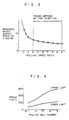
- Fig. 4 relates to one of the standard types of conventional continuous multi-stand mill plants for rolling steel plates, namely, a 5-stand tandem rolling mill plant for producing cold-rolled steel plates of medium and increased thickness.
- the ordinate represents rolling speeds, and each number on the abscissa represents a corresponding rolling mill stand.
- the form of an area between the lower and upper limit lines in each figure is herein-after referred to as a speed cone, and the ratio of maximum rolling speed to minimum rolling speed is referred to as the rolling speed ratio.
- the rolling speed ratio of a steel rolling multi-stand mill plant is generally about 2.0 and less than 3.0, as shown in "Iron and Steel Manual” (Vol. 3) (2) (November 20, 1980) edited by The Iron and Steel Institute of Japan, Maruzen, p. 1349. This value is due to the limitation in current rate of a direct-current motor based on the commutating ability described above.
- a conventional method of, for example, producing cold-rolled steel plates involves a plurality of rolling mill plant rows such as rolling mill plants for processing thin and thick material, respectively.
- the range of dimensions and qualities of a steel plate processed by each of these rolling mill plants are set to be comparatively narrow so as to correspond to a rolling speed ratio of less than 3.0. This arrangement has been necessitated by the need to produce different types of product of differing thicknesses.
- a speed cone is such as shown in Fig. 6, since the ratio of the original plate thickness of a material to be processed before rolling to the product thickness after rolling, namely, the rolling reduction ratio is small, as shown, for example, at Nos. 3 to 14 in Table 2, the difference between rolling speeds at the initial and final rolling mills thereby being small.
- a speed cone is such as shown in Fig. 7, as the rolling reduction ratio is large, as shown, for example, at Nos. 1 and 2 in Table 2. In both cases, it is possible for material adapted to each design to be rolled within the area of speed cones, and the power of rolling mills to be used efficiently.
- the continuous rated output of an electric motor adapted to rolling mills for rolling materials having a wide range of dimensions and qualities can be highly reduced compared with the conventional continuous mill plant, and rolling mill plants for respectively processing thick and thin materials can be integrated into one rolling mill plant.
- a speed-varying transmission and a final reduction gear is provided between a motor and a roll, and is employed in a rolling mill for testing its minimum and maximum rolling speeds at the continuous rated output of the motor; the driving speed of the roll can be freely changed from 5 mpm to 100 mpm. Then, materials shown in Table 1 are rolled respectively at the rolling speed ratios of 2.0, 2.5, 3.0, 4.0, 5.0, 6.0, 7.0, 8.0 and 10.0 through five passes of the original plate thickness to the product thickness.
- each continuous rated output of the motor necessitated when materials shown in Table 2 are rolled by the single rolling mill plant at the prescribed efficiency and rate is calculated, and the relationship between the rolling speed ratio and the continuous rated output of the motor is shown in Fig. 3 by assuming that the continuous rated output ratio of the motor is 1.0 at the rolling sped ratio of 2.5.
- the degree of freedom of selecting and adapting the rolling speeds suitable for dimensions and qualities of the material to be processed is increased, so that the irregular use of the motor deviating from the rating can be reduced, the continuous rated output of the motor thereby being reduced comparatively.
- the rolling speed ratio becomes lower than 3.0, the ratio of required continuous rated output of the motor increases abruptly.
- the former is between 3.0 and 10.0, the latter decreases gradually and stably.
- the former is equal to or more than 5.0, the latter becomes less than 0.6 so as to heighten the effect of limiting the motor capacity.
- the ratio of required continuous rated output saturates when the rolling speed ratio is above 10.0.
- the suitable rolling speed ratio is at least 4.0 but not more than 10.0 and is preferably 5.0 or more and not more than 10.0.
- Fig. 5 shows a speed cone of a rolling mill plant for rolling thick material whose rolling speed ratio is 2.5, and which is modified by the provision of transmissions at each stand and changing the speed ratio at each stand individually so as to obtain a rolling speed ratio of 5.0, thereby assuring that materials of a wide ranges of dimensions and qualities can be rolled.
- Fig. 1 is a front view of a rolling mill provided by modifying a conventional rolling mill for a thick material on the basis of the present invention.
- the power generated by a direct-current motor 1 is supplied through a first intermediate shaft 2 to a speed-varying transmission 3 (hatched), and through a second intermediate shaft 4 to a final reduction gear 5.
- the rest of the rolling mill is the same as it was before the modification.
- An alternating-current motor which affords a rolling speed ratio of 5.0 has been adapted so that it can be substituted for a direct-current motor in the conventional rolling mill plant, resulting in the same effects without having to provide any speed-varying transmission of the above modification which enables materials of differing thicknesses to be easily rolled.
- Fig. 2 shows another embodiment of the present invention, in which an alternating-current motor whose rolling speed ratio is 9.0 is adapted to a 6-high rolling mill.
- An alternating-current motor 11 (hatched) is driven with the output power from a cycloconverter 13.
- the output frequency from the cycloconverter 13 is adjusted by using a speed-control device 14 in case changing of the rolling speed is required.
- the power is transmitted through an intermediate shaft 12, a final reduction gear 5, and upper and lower spindles 6 and 7 to an upper work roll 8 and a lower work roll 9.
- an alternating-current motor having a rolling speed ratio of 9.0 has been adapted, and the desired productivity has been obtained in the processing of both thick and thin materials, the continuous rated output of the motor being reduced by 25% of that of an alternating-current motor adapted so as to have a rolling speed ratio of 5.0.
Landscapes
- Engineering & Computer Science (AREA)
- Mechanical Engineering (AREA)
- Metal Rolling (AREA)
- Control Of Metal Rolling (AREA)
- Control Of Ac Motors In General (AREA)
- Control Of Multiple Motors (AREA)
Description
- The present invention relates to a continuous multi-stand mill plant for rolling steel plates which is designed to work at minimum rolling power.
- Electric motors in general include direct-current motors and alternating-current motors. To date, most of the motors which have been used in rolling mills have been direct-current motors, since sufficient frequency conversion techniques have not been developed for controlling the speed of altemating-current motors. However, increases in capacity of direct-current motors have been limited in terms of commutating ability.
- The characteristics of such a conventional direct-current motor for rolling will be described with reference to the accompanying drawings. Fig. 4 relates to one of the standard types of conventional continuous multi-stand mill plants for rolling steel plates, namely, a 5-stand tandem rolling mill plant for producing cold-rolled steel plates of medium and increased thickness. The ordinate represents rolling speeds, and each number on the abscissa represents a corresponding rolling mill stand. In this figure are depicted a line (lower limit) connecting the minimum rolling speed points and a line (upper limit) connecting the maximum rolling speed points defined at the continuous rated output of a motor for driving each rolling mill. The form of an area between the lower and upper limit lines in each figure is herein-after referred to as a speed cone, and the ratio of maximum rolling speed to minimum rolling speed is referred to as the rolling speed ratio. The rolling speed ratio of a steel rolling multi-stand mill plant is generally about 2.0 and less than 3.0, as shown in "Iron and Steel Manual" (Vol. 3) (2) (November 20, 1980) edited by The Iron and Steel Institute of Japan, Maruzen, p. 1349. This value is due to the limitation in current rate of a direct-current motor based on the commutating ability described above.
- For a single-stand cold rolling mill a drive-speed range from 200 to 740 r.p.m. is known from Brown Boveri Mitteilungen, Vol. 60, No. 10/11, 1973.
- From the above speed cone characteristics of a multi-stand rolling mill plant using a direct-current motor, a conventional method of, for example, producing cold-rolled steel plates, involves a plurality of rolling mill plant rows such as rolling mill plants for processing thin and thick material, respectively. The range of dimensions and qualities of a steel plate processed by each of these rolling mill plants are set to be comparatively narrow so as to correspond to a rolling speed ratio of less than 3.0. This arrangement has been necessitated by the need to produce different types of product of differing thicknesses.
- The relationship between speed cone characteristic and degree of rolling is described below with respect to rolling mill plants for respectively processing thin and thick material. In a rolling mill plant for thick material, a speed cone is such as shown in Fig. 6, since the ratio of the original plate thickness of a material to be processed before rolling to the product thickness after rolling, namely, the rolling reduction ratio is small, as shown, for example, at Nos. 3 to 14 in Table 2, the difference between rolling speeds at the initial and final rolling mills thereby being small. Conversely, in a rolling mill plant for thin material, a speed cone is such as shown in Fig. 7, as the rolling reduction ratio is large, as shown, for example, at Nos. 1 and 2 in Table 2. In both cases, it is possible for material adapted to each design to be rolled within the area of speed cones, and the power of rolling mills to be used efficiently.
- On the other hand, when thick and thin materials are processed by a conventional rolling mill plant of either the type for processing thick material or the type for thin material with a view to eliminating or reducing the investment in labor and installations from the level currently needed, there is a problem of difficulty in performing rolling or of inefficient use of rolling mill power.
- In a rolling mill plant for processing thick material and having such speed cone as shown in Fig. 6, when a thin material such as, for example, shown at Nos. 1 and 2 in Table 2 is rolled, the rolling speed is restricted to the upper limit of the speed cone at the final stand, and thus at each of the first to fourth stands even though there is some power margin. The rolling speed at the first stand is thereby reduced below the lower limit of the speed cone. Thus, the power of the rolling mill is not efficiently used, and the efficiency of production is considerably reduced compared with the rolling performed by rolling mill plants for processing thin material.
- Conversely, when a thick material such as, for example, shown at No. 14 in Table 2 is rolled by a rolling mill plant for processing thin material and having a speed cone such as shown in Fig. 7, the rolling speed at all rolling-stands can not be heightened to the lower limit of the speed cone, the rolling itself thereby being extremely difficult.
- Thus, in the conventional rolling mill plants, there has been severe restrictions on the ranges of dimensions and qualities of a material to be rolled. There has not been any known practical techniques which enable a rolling mill plant to work over the whole processing range without this defect.
- It is an object of the present invention to provide a continuous multi-stand mill plant for rolling steel plates which ensures that materials to be processed and having a wide range of dimensions and qualities are rolled by using the whole effective power of the rolling mill stands. This object is achieved by the continuous multi-stand mill plant according to the claims.
No. Original plate thickness Product thickness Width Rolling reduction ratio 1 2.3 0.25 35 9.2 2 2.3 0.30 35 7.7 3 2.5 0.70 35 3.8 4 2.5 0.70 50 3.6 5 2.5 0.70 65 3.6 6 3.0 1.00 35 3.0 7 3.0 1.00 50 3.0 8 3.0 1.00 65 3.0 9 3.5 1.40 50 2.5 10 3.5 1.40 50 2.5 11 4.5 2.30 65 2.0 12 4.5 2.30 65 2.0 13 6.0 3.20 65 1.9 14 6.0 3.20 80 1.9 Unit: mm No. Original plate thickness Product thickness Width Rolling reduction ratio 1 2.3 0.25 700 9.2 2 2.3 0.30 700 7.7 3 2.5 0.70 700 3.6 4 2.5 0.70 1000 3.6 5 2.5 0.70 1300 3.8 6 3.0 1.00 700 3.0 7 3.0 1.00 1000 3.0 8 3.0 1.00 1300 3.0 9 3.5 1.40 1000 2.5 10 3.5 1.40 1000 2.5 11 4.5 2.30 1300 2.0 12 4.5 2.30 1300 2.0 13 6.0 3.20 1300 1.9 14 6.0 3.20 1600 1.9 Unit: mm - According to the present invention, the continuous rated output of an electric motor adapted to rolling mills for rolling materials having a wide range of dimensions and qualities can be highly reduced compared with the conventional continuous mill plant, and rolling mill plants for respectively processing thick and thin materials can be integrated into one rolling mill plant.
- Next, the reason for limiting the values is described. A speed-varying transmission and a final reduction gear is provided between a motor and a roll, and is employed in a rolling mill for testing its minimum and maximum rolling speeds at the continuous rated output of the motor; the driving speed of the roll can be freely changed from 5 mpm to 100 mpm. Then, materials shown in Table 1 are rolled respectively at the rolling speed ratios of 2.0, 2.5, 3.0, 4.0, 5.0, 6.0, 7.0, 8.0 and 10.0 through five passes of the original plate thickness to the product thickness. From the rolling speeds measured at each pass, each continuous rated output of the motor necessitated when materials shown in Table 2 are rolled by the single rolling mill plant at the prescribed efficiency and rate is calculated, and the relationship between the rolling speed ratio and the continuous rated output of the motor is shown in Fig. 3 by assuming that the continuous rated output ratio of the motor is 1.0 at the rolling sped ratio of 2.5. As is shown in this figure, in the region of small rolling speed ratios, the rolling operation deviated from the rated output which is necessitated by the need to process materials of differing thicknesses so that the rated output is set largely in safety by adding a desired margin, since the ranges of dimensions and qualities of the material to be processed are narrow. When the rolling speed ratio is large, the degree of freedom of selecting and adapting the rolling speeds suitable for dimensions and qualities of the material to be processed is increased, so that the irregular use of the motor deviating from the rating can be reduced, the continuous rated output of the motor thereby being reduced comparatively.
- Thus, when the rolling speed ratio becomes lower than 3.0, the ratio of required continuous rated output of the motor increases abruptly. When the former is between 3.0 and 10.0, the latter decreases gradually and stably. When the former is equal to or more than 5.0, the latter becomes less than 0.6 so as to heighten the effect of limiting the motor capacity. The ratio of required continuous rated output saturates when the rolling speed ratio is above 10.0. The suitable rolling speed ratio is at least 4.0 but not more than 10.0 and is preferably 5.0 or more and not more than 10.0.
- The invention is described in detail with reference to the accompanying drawings in which
- Fig. 1 is a front view showing a rolling mill which is an embodiment of the present invention;
- Fig. 2 is a front view showing a rolling mill which is another embodiment of the present invention;
- Fig. 3 is a diagram showing the relationship between the ratio of the required continuous rated output of a motor and the rolling speed ratio;
- Fig. 4 is a diagram showing a general speed cone of a continuous mill plant for rolling steel plates;
- Fig. 5 is a diagram showing a speed cone of a rolling mill modified according to the present invention;
- Fig. 6 is a diagram showing a speed cone of the conventional rolling mill plant for rolling a thick material; and
- Fig. 7 is a diagram showing a speed cone of the conventional rolling mill plant for rolling a thin material.
-
- Fig. 5 shows a speed cone of a rolling mill plant for rolling thick material whose rolling speed ratio is 2.5, and which is modified by the provision of transmissions at each stand and changing the speed ratio at each stand individually so as to obtain a rolling speed ratio of 5.0, thereby assuring that materials of a wide ranges of dimensions and qualities can be rolled.
- Fig. 1 is a front view of a rolling mill provided by modifying a conventional rolling mill for a thick material on the basis of the present invention. The power generated by a direct-
current motor 1 is supplied through a firstintermediate shaft 2 to a speed-varying transmission 3 (hatched), and through a secondintermediate shaft 4 to afinal reduction gear 5. The rest of the rolling mill is the same as it was before the modification. - As a result, thin materials such as those shown at Nos. 1 and 2 in Table 2, which are processed at an extremely low efficiency by conventional rolling, are efficiently rolled by the above arrangement. Thus all the materials shown in Table 2 can be processed without having to increase the capacity of a conventional direct-current motor having a continuous rated output which is only 55% of the continuous rated output required when materials of differing thicknesses are processed at appropriate production efficiencies, when employing a single rolling mill plant whose rolling speed ratio is 2.5 as the conventional level. The results obtained by this processing are the same as those obtained by a rolling mill plant using direct-current motors of a desired continuous rated output level.
- Recent improvements in the performance of semi-conductors and computers have made the process of converting the frequency of a power source easier. The controllability of alternating-current motors are thereby so greatly improved that they can be used as motors for driving a rolling mill plant. Regarding speed control of alternating-current motors, there are pole changing control and frequency changing control. The pole changing control is only suitable for discontinuous speed control of alternating-current motors, and so such frequency changing control is indispensable for the continuous mill plant for rolling steel plates in which minute speed control such as tension control between rolling stands is required.
- An alternating-current motor which affords a rolling speed ratio of 5.0 has been adapted so that it can be substituted for a direct-current motor in the conventional rolling mill plant, resulting in the same effects without having to provide any speed-varying transmission of the above modification which enables materials of differing thicknesses to be easily rolled.
- Fig. 2 shows another embodiment of the present invention, in which an alternating-current motor whose rolling speed ratio is 9.0 is adapted to a 6-high rolling mill. An alternating-current motor 11 (hatched) is driven with the output power from a
cycloconverter 13. The output frequency from thecycloconverter 13 is adjusted by using a speed-control device 14 in case changing of the rolling speed is required. The power is transmitted through an intermediate shaft 12, afinal reduction gear 5, and upper andlower spindles upper work roll 8 and alower work roll 9. - In this way, an alternating-current motor having a rolling speed ratio of 9.0 has been adapted, and the desired productivity has been obtained in the processing of both thick and thin materials, the continuous rated output of the motor being reduced by 25% of that of an alternating-current motor adapted so as to have a rolling speed ratio of 5.0.
Claims (4)
- A continuous multi-stand mill plant for producing steel plates wherein the ratio of maximum rolling speed to minimum rolling speed is at least 4.0 but not more than 10.0 at the continuous rated output of one or of a plurality of electric motor(s) (11) for driving at least one of said rolling mill stands, and having means (13, 14) for controlling the speed of said motor(s) (11) in accordance with said ratio, wherein said electric motor(s) (11) are alternating-current motor(s).
- A continuous multi-stand mill plant for producing steel plates wherein a speed-varying transmission is provided between a rolling mill stand and its electric drive motor so as to achieve a ratio of maximum rolling speed to minimum rolling speed of at least 4.0 but not more than 10.0 at the continuous rated output of one or a plurality of electric motor(s) for driving at least one of said rolling mill stands.
- A continuous multi-stand mill plant for producing steel plates according to Claim 1 or 2, wherein said rolling mill is a rolling mill for cold-rolling steel plate.
- A continuous multi-stand mill plant according to claim 3, wherein the speed ratio of the motors of all said rolling mill stands is at least 4.0 but not more than 10.0 at the continuous rated output.
Applications Claiming Priority (3)
| Application Number | Priority Date | Filing Date | Title |
|---|---|---|---|
| JP3453385 | 1985-02-25 | ||
| JP34533/85 | 1985-02-25 | ||
| JP3453385 | 1985-02-25 |
Publications (3)
| Publication Number | Publication Date |
|---|---|
| EP0193155A1 EP0193155A1 (en) | 1986-09-03 |
| EP0193155B1 EP0193155B1 (en) | 1989-10-11 |
| EP0193155B2 true EP0193155B2 (en) | 2003-03-26 |
Family
ID=12416911
Family Applications (1)
| Application Number | Title | Priority Date | Filing Date |
|---|---|---|---|
| EP86102364A Expired - Lifetime EP0193155B2 (en) | 1985-02-25 | 1986-02-24 | Continuous multi-stand mill plant for rolling steel plates |
Country Status (8)
| Country | Link |
|---|---|
| US (1) | US4882923A (en) |
| EP (1) | EP0193155B2 (en) |
| JP (1) | JPS623820A (en) |
| KR (1) | KR900002148B1 (en) |
| CN (1) | CN1033953C (en) |
| BR (1) | BR8600754A (en) |
| CA (1) | CA1271349A (en) |
| DE (1) | DE3666156D1 (en) |
Families Citing this family (6)
| Publication number | Priority date | Publication date | Assignee | Title |
|---|---|---|---|---|
| SE508304C2 (en) * | 1993-03-15 | 1998-09-21 | Morgaardshammar Ab | Drive device for roller pairs |
| KR960016127B1 (en) * | 1994-02-01 | 1996-12-04 | 주식회사 태평양 | Kojic acid derivatives |
| US6189352B1 (en) * | 1996-05-21 | 2001-02-20 | Siemens Aktiengesellschaft | Drive device for roll stands |
| DE19647637A1 (en) * | 1996-11-18 | 1998-05-28 | Siemens Ag | Rolling mill with at least one roll stand with three-phase drive system |
| ITPD20130309A1 (en) | 2013-11-14 | 2015-05-15 | Piaggio & C Spa | MOTORCYCLE TRANSMISSION OF HOMOCINETARY TYPE, AND MOTORCYCLE INCLUDING THE TRANSMISSION |
| CN117225895A (en) * | 2023-09-21 | 2023-12-15 | 陕西星航智钛新材料有限公司 | A method for preparing large plate heavy Ti6Al4V titanium alloy hot-rolled strips |
Family Cites Families (12)
| Publication number | Priority date | Publication date | Assignee | Title |
|---|---|---|---|---|
| US1716039A (en) * | 1926-07-17 | 1929-06-04 | Fries Joens Elias | Rolling mill |
| US2131541A (en) * | 1936-08-25 | 1938-09-27 | Stanley Works | Rolling mill drive |
| US3074300A (en) * | 1959-04-20 | 1963-01-22 | Beloit Iron Works | Automatic control and drive for mills |
| US3213656A (en) * | 1963-01-31 | 1965-10-26 | Westinghouse Electric Corp | Rolling mill motor speed control apparatus |
| US3655950A (en) * | 1969-10-22 | 1972-04-11 | Cutler Hammer Inc | Percentage elongation calibrated digital pulse deleter |
| US3762194A (en) * | 1972-06-28 | 1973-10-02 | Gen Electric | Constant speed driven continuous rolling mill |
| JPS5147421B2 (en) * | 1972-11-30 | 1976-12-15 | ||
| US3913368A (en) * | 1974-09-04 | 1975-10-21 | Blaw Knox Foundry Mill Machine | Tandem rolling mill |
| DE2736659A1 (en) * | 1977-08-13 | 1979-02-22 | Krupp Gmbh | ROLLER LINE DRIVE SYSTEM |
| JPS6031191B2 (en) * | 1978-04-26 | 1985-07-20 | ファナック株式会社 | DC motor control method |
| JPS59181992A (en) * | 1983-03-31 | 1984-10-16 | Toshiba Corp | Controlling method of tension between stands of continuous rolling mill |
| JPS59213252A (en) * | 1983-05-17 | 1984-12-03 | Mitsubishi Electric Corp | Ac rotary electric machine for driving rolling mill |
-
1986
- 1986-02-13 JP JP61027807A patent/JPS623820A/en active Granted
- 1986-02-24 CA CA000502526A patent/CA1271349A/en not_active Expired - Lifetime
- 1986-02-24 DE DE8686102364T patent/DE3666156D1/en not_active Expired
- 1986-02-24 BR BR8600754A patent/BR8600754A/en not_active IP Right Cessation
- 1986-02-24 CN CN86101770A patent/CN1033953C/en not_active Expired - Lifetime
- 1986-02-24 EP EP86102364A patent/EP0193155B2/en not_active Expired - Lifetime
- 1986-02-25 KR KR1019860001322A patent/KR900002148B1/en not_active Expired
-
1989
- 1989-03-03 US US07/319,828 patent/US4882923A/en not_active Expired - Lifetime
Also Published As
| Publication number | Publication date |
|---|---|
| KR900002148B1 (en) | 1990-04-02 |
| KR860006298A (en) | 1986-09-09 |
| EP0193155A1 (en) | 1986-09-03 |
| CA1271349A (en) | 1990-07-10 |
| JPH0456685B2 (en) | 1992-09-09 |
| US4882923A (en) | 1989-11-28 |
| EP0193155B1 (en) | 1989-10-11 |
| DE3666156D1 (en) | 1989-11-16 |
| CN86101770A (en) | 1986-10-15 |
| BR8600754A (en) | 1986-11-04 |
| JPS623820A (en) | 1987-01-09 |
| CN1033953C (en) | 1997-02-05 |
Similar Documents
| Publication | Publication Date | Title |
|---|---|---|
| JP3174457B2 (en) | Continuous casting direct hot rolling equipment and rolling method | |
| US4566299A (en) | Control method and apparatus for rolling mill | |
| US4817703A (en) | Strip casing unit with downstream multi-stand continuous rolling mill | |
| US4408474A (en) | Metal strip stretching mill | |
| EP0193155B1 (en) | Continuous multi-stand mill plant for rolling steel plates | |
| CN108284133B (en) | Ultra-thin steel strip rolling process method for single-stand reversible rolling mill | |
| US4020667A (en) | Tube rolling | |
| JPH027723B2 (en) | ||
| JPH0236323B2 (en) | ||
| US2416180A (en) | Electric motor control system | |
| JPH03297513A (en) | Tension control method for thin plate mill winding machine | |
| Kuznetsov et al. | Improvement of the regulation system for the electric drive of rolls rotation in the rolling mill | |
| JPS6030967Y2 (en) | Rolling mill elongation control device | |
| JP2024038802A (en) | electric motor drive device | |
| JP2760264B2 (en) | Method and apparatus for controlling thickness of tandem rolling mill | |
| US20050016242A1 (en) | Continous hot-rolling facility | |
| JPH0313226A (en) | Driving device for rolling mill | |
| JPH0325243B2 (en) | ||
| JPH0234243B2 (en) | ||
| Peck | Modern rolling mill drives | |
| JPS58107202A (en) | Rolling mill | |
| CN117983694A (en) | A stable coiling method for thin strip steel | |
| JPS56117819A (en) | Controlling method for tension of rolling mill | |
| Bordeau et al. | Synchronous motors in rolling mill service | |
| JP2001047115A (en) | Wire rolling mill |
Legal Events
| Date | Code | Title | Description |
|---|---|---|---|
| PUAI | Public reference made under article 153(3) epc to a published international application that has entered the european phase |
Free format text: ORIGINAL CODE: 0009012 |
|
| AK | Designated contracting states |
Kind code of ref document: A1 Designated state(s): DE FR GB |
|
| 17P | Request for examination filed |
Effective date: 19870126 |
|
| 17Q | First examination report despatched |
Effective date: 19880316 |
|
| GRAA | (expected) grant |
Free format text: ORIGINAL CODE: 0009210 |
|
| AK | Designated contracting states |
Kind code of ref document: B1 Designated state(s): DE FR GB |
|
| REF | Corresponds to: |
Ref document number: 3666156 Country of ref document: DE Date of ref document: 19891116 |
|
| ET | Fr: translation filed | ||
| PLBI | Opposition filed |
Free format text: ORIGINAL CODE: 0009260 |
|
| 26 | Opposition filed |
Opponent name: SIEMENS AKTIENGESELLSCHAFT, BERLIN UND MUENCHEN Effective date: 19900530 |
|
| PLBI | Opposition filed |
Free format text: ORIGINAL CODE: 0009260 |
|
| 26 | Opposition filed |
Opponent name: SMS SCHLOEMANN-SIEMAG AG Effective date: 19900704 Opponent name: SIEMENS AKTIENGESELLSCHAFT, BERLIN UND MUENCHEN Effective date: 19900530 |
|
| APAC | Appeal dossier modified |
Free format text: ORIGINAL CODE: EPIDOS NOAPO |
|
| PLAW | Interlocutory decision in opposition |
Free format text: ORIGINAL CODE: EPIDOS IDOP |
|
| APAC | Appeal dossier modified |
Free format text: ORIGINAL CODE: EPIDOS NOAPO |
|
| APAE | Appeal reference modified |
Free format text: ORIGINAL CODE: EPIDOS REFNO |
|
| APAC | Appeal dossier modified |
Free format text: ORIGINAL CODE: EPIDOS NOAPO |
|
| REG | Reference to a national code |
Ref country code: GB Ref legal event code: IF02 |
|
| PLBQ | Unpublished change to opponent data |
Free format text: ORIGINAL CODE: EPIDOS OPPO |
|
| PLAB | Opposition data, opponent's data or that of the opponent's representative modified |
Free format text: ORIGINAL CODE: 0009299OPPO |
|
| PLBQ | Unpublished change to opponent data |
Free format text: ORIGINAL CODE: EPIDOS OPPO |
|
| PLAB | Opposition data, opponent's data or that of the opponent's representative modified |
Free format text: ORIGINAL CODE: 0009299OPPO |
|
| APAC | Appeal dossier modified |
Free format text: ORIGINAL CODE: EPIDOS NOAPO |
|
| R26 | Opposition filed (corrected) |
Opponent name: SIEMENS AG * 19900704 SMS SCHLOEMANN-SIEMAG AG Effective date: 19900530 |
|
| R26 | Opposition filed (corrected) |
Opponent name: SIEMENS AG * 19900704 SMS SCHLOEMANN-SIEMAG AG Effective date: 19900530 |
|
| PLAW | Interlocutory decision in opposition |
Free format text: ORIGINAL CODE: EPIDOS IDOP |
|
| PUAH | Patent maintained in amended form |
Free format text: ORIGINAL CODE: 0009272 |
|
| STAA | Information on the status of an ep patent application or granted ep patent |
Free format text: STATUS: PATENT MAINTAINED AS AMENDED |
|
| 27A | Patent maintained in amended form |
Effective date: 20030326 |
|
| AK | Designated contracting states |
Designated state(s): DE FR GB |
|
| ET3 | Fr: translation filed ** decision concerning opposition | ||
| PGFP | Annual fee paid to national office [announced via postgrant information from national office to epo] |
Ref country code: FR Payment date: 20050208 Year of fee payment: 20 |
|
| PGFP | Annual fee paid to national office [announced via postgrant information from national office to epo] |
Ref country code: DE Payment date: 20050217 Year of fee payment: 20 |
|
| PGFP | Annual fee paid to national office [announced via postgrant information from national office to epo] |
Ref country code: GB Payment date: 20050223 Year of fee payment: 20 |
|
| REG | Reference to a national code |
Ref country code: GB Ref legal event code: PE20 |
|
| APAH | Appeal reference modified |
Free format text: ORIGINAL CODE: EPIDOSCREFNO |
|
| PG25 | Lapsed in a contracting state [announced via postgrant information from national office to epo] |
Ref country code: GB Free format text: LAPSE BECAUSE OF EXPIRATION OF PROTECTION Effective date: 20060223 |