EP0192622A2 - Drilling equipment for percussive drilling - Google Patents
Drilling equipment for percussive drilling Download PDFInfo
- Publication number
- EP0192622A2 EP0192622A2 EP86850038A EP86850038A EP0192622A2 EP 0192622 A2 EP0192622 A2 EP 0192622A2 EP 86850038 A EP86850038 A EP 86850038A EP 86850038 A EP86850038 A EP 86850038A EP 0192622 A2 EP0192622 A2 EP 0192622A2
- Authority
- EP
- European Patent Office
- Prior art keywords
- thread
- conversion connector
- drill rod
- drill
- rod
- Prior art date
- Legal status (The legal status is an assumption and is not a legal conclusion. Google has not performed a legal analysis and makes no representation as to the accuracy of the status listed.)
- Withdrawn
Links
Images


Classifications
-
- E—FIXED CONSTRUCTIONS
- E21—EARTH OR ROCK DRILLING; MINING
- E21B—EARTH OR ROCK DRILLING; OBTAINING OIL, GAS, WATER, SOLUBLE OR MELTABLE MATERIALS OR A SLURRY OF MINERALS FROM WELLS
- E21B17/00—Drilling rods or pipes; Flexible drill strings; Kellies; Drill collars; Sucker rods; Cables; Casings; Tubings
- E21B17/02—Couplings; joints
- E21B17/04—Couplings; joints between rod or the like and bit or between rod and rod or the like
- E21B17/042—Threaded
- E21B17/0426—Threaded with a threaded cylindrical portion, e.g. for percussion rods
-
- E—FIXED CONSTRUCTIONS
- E21—EARTH OR ROCK DRILLING; MINING
- E21B—EARTH OR ROCK DRILLING; OBTAINING OIL, GAS, WATER, SOLUBLE OR MELTABLE MATERIALS OR A SLURRY OF MINERALS FROM WELLS
- E21B17/00—Drilling rods or pipes; Flexible drill strings; Kellies; Drill collars; Sucker rods; Cables; Casings; Tubings
Definitions
- the present invention relates to drilling equipment for percussive drilling, said equipment comprising an annular drill bit and a drill rod system attached to the drill bit; the percussive and rotative drive are brought to the drill rod system by equipment located above the ground level.
- a great problem of currently used drilling equipment systems has been the quality of the drillhole being drilled.
- the most widely used equipment consists of such a drilling stem system in which drilling stems of a diameter considerably smaller than the diameter of the bit and its stem is attached to the drill bit. This means that the drill bit with its short stem is not adequately supported by the walls of the drillhole.
- the controllability of the drill is bad and the danger of bending is great; the probability of the collapse of the drillhole is very obvious.
- the flushing characteristics of this well-known and conventional drill bit/drill rod combination are also very poor, which further worsens the support provided for the drill by the walls of the drillhole. With insufficient flushing, drilling dust and cuttings will pile up in the outer flushing channel, which also prevents the rod section from evening up the drillhole and being supported by its wall. Therefore the support will be very uneven.
- the Applicants published Finnish application No. 824126 depicts such a drill rod system, in which the steel cross-section of the tubular drill rod is so dimensioned as to provide good flushing of the drillhole.
- the rod systems must also be easy to handle; therefore the outer cross-section of each rod unit should be as small as possible in order to properly fit into the drill rod magazine.
- a solution in accordance with the invention provides an entirely new unit comprising the annular drill bit, the rod system and a connector piece (conversion connector); this unit gives good support to the annular drill bit, creates good-quality drillholes and makes the handling of the whole rod system good and optimized.
- a drilling equipment combination in accordance with the invention comprises, except for the conversion connector, only existing components known as such. It provides a new possibility to make use of existing drilling equipment in a new feasible way.
- the invention combines the advantages of tubular drilling equipment and rod-type drilling equipment at the same time eliminating their drawbacks. Old drilling equipment, maganizines included, may be used with the new combination without any modifications. So there will be no need to renew old drill rod magazines and cassettes.
- the invention is based on the idea that an annular drill bit can, in the vicinity of the drill bit, be supported with one or two tubular support bars.
- drilling dust and cuttings must not, in the vicinity of the drill bet, be packed between the drill rod and the walls of the drillhole being created. Therefore there must also be adequate flushing, so that drilling dust and cuttings will be taken away from said area supporting the drill bit.
- a rod system in which the cross-section of a center flushing channel is essentially as large as the cross-section of an outer flushing channel in order to prevent any constriction.
- Said way of shaping the rod also ; makes it possible to make the outer flushing channel relatively narrow; in other words the outer wall of the drill rod is close to the wall of the wall of the drillhole being formed, which is a prerequisite of good support. There will be little room for the drill rod to bend in the drillhole; should the drill deviate from its original direction, the drill rod will touch the wall of the drillhole already drilled, which will prevent the drill from deviating any more.
- Said narrowness of the outer flushing channel also prevents stones or other rather large pieces of earth from dropping from the walls of the drillhole into the drillhole.
- the diameter of the rest of the rods is essentially smaller, which makes the whole combination easy to handle. The smaller is the outer diameter of a rod, the easier it is to fit the rods into a drill rod magazine, as small-diameter rods take essentially less room than rods that are largish in diameter.
- An essential feature of a combination in accordance with the invention is that the outer surface of the section of the drill rod system located in the vicinity of the drill bit has essentially no steps.
- the outer diameter of the drill bit, the outer diameter of the tubular drill rod, and the outer diameter of the broadest point of the connector piece or the conversion connector in accordance with the invention are then essentially equal, which provides a no-constriction passage for the flushing liquid in the outer flushing channel.
- Another essential feature of the invention is that it is sufficient to equip the section near the drill bit with a combination which provides good support and good flushing, because it is this section near the drill bit that is the most critical from the point of view of the quality of the drillhole being drilled.
- the rod system In order to be able to transmit the impacts of the drilling machine as efficiently as possible from a smaller-diameter shaft section to the tubular drill shaft providing support, the rod system must be equipped with a connector piece (conversion connector).
- This connector piece must be so shaped as to keep the steel cross-section essentially constant when proceeding from the surface of the smaller-diameter rod end mating the connector piece to the surface of the connector piece mating the end of the larger-diameter tubular drill rod. This will prevent reflection of impact energy and shock waves, i.e. impact energy losses.
- An essential feature of the connector piece is that impact energy is specifically transmitted by the end faces so that the threads will not take the loading; they are only for tightening the rod ends up against the mating surfaces of the connector piece.
- the connector piece is designed as a thread conversion connector; the external thread at one end of the connector piece mates the internal thread of the tubular supporting rod; the preferable thread system will be described below.
- the thread system of the internal thread at the other end of the conversion connector can be chosen freely. This I:ind of conversion connector in accordance with the invention gives flexibility to the drilling equipment combination. The user may then choose a conversion connector, which, at one end, has a thread that mates with the thread of the his drill rod system and the drill rod system connected with the drilling machine.
- the principal characteristic feature of the invention is that the drilling equipment is composed of a combination which comprises ⁇
- the invention also relates to the conversion connector, whose principal characteristic feature is that it comprises the first coupling thread located at one end of its body section, and the second coupling thread located at the other end, said threads representing different thread systems.
- D 1 denotes the diameter of a hole being drilled
- D 2 denotes the outer diameter of the drill bit
- D 3 denotes the outer diameter of the tubular drill rod fastened to the shaft of the bit at one end and to one end of the conversion connector 14 at the other end.
- D 4 denotes the largest diameter of the center section of the conversion connector 14, and D 5 denotes the outer diameter of the rod fastened to the other end of the conversion connector with a threaded joint.
- drill rods 12 There might be 1 to 3 drill rods as required.
- the number of drill rods 12 depends on their length, for instance.
- the lenght of one drill rod is preferably between 1500 to 6100 mm.
- Diameters D 2 to D 4 as essentially equal to each other for smooth and stepless surface.
- the narrow outer flushing channel provides a suf- fi c ient flushing speed and consequently a sufficiently efficient removal of drilling dust and cuttings, and as this part of the rod system has an essentially smooth outer surface, there will be no constrictions which would impede the removal of drilling dust and cuttings and also have detrimental influence on consumption of energy by the flushing medium.
- Figure 2 also shows the tubular rod 12 with a partial section view in order to show the central flushing channel.
- D 6 denotes the diameter of the central flushing channel.
- the cross-section area of the central flushing channel of the tubular drill bar 12 is made essentially equal to the cross-section area of the outer flushing channel. Then there will be no energy-wasting constrictions. ; Shaping the rod in the described manner also results in a relatively narrow outer flushing channel, whereat the speed of the flushing medium will be high enough, and also the structure will such as to keep the outer face of the drill rod very close to the wall of the drillhole being formed, which is a prerequisite of good support and minimum tilting of the drill rod in the drillhole. Now there will not be much room for the drill bar to bend in the drillhole; as the drill deviates from its original direction, the drill bar will touch the wall of the drill hole thus preventing the drill from deviating further.
- Figure 3 shows a longitudinal section view of the conversion connector 13 in an enlarged scale.
- the conversion connector is an elongated cylindrical piece, symmetrical as to its longitudinal axis. At one end it has a thread 15 for fastening it to the tubular drill rod 12; at the other end it has a thread 16 for fastening it to the smaller-diameter drill rod 13.
- the thread 15 is preferably an external thread; the thread 16 is preferably an internal thread.
- the thread 15 mate the end thread of the tubular drill rod 12, and it has been selected from a thread system in which the thread angle and the profile height h mainly remain constant independently of the outer diameter D of the tubular drill bar 12, wherat the pitch of the thread and the number of thread heads n increase as the outer diameter D of the tubular drill rod 12 increases.
- the thread has been selected as follows: if the outer diameter D of the tubular drill rod 12 is smaller than 70 mm, the thread is one-headed and its pitch is less than 23 mm; if the outer diameter of the tubular drill rod 12 is 70 to 152 mm, the thread is two-headed and its pitch is 23 to 45 mm; if the outer diameter of the tubular drill rod 12 is over 152 mm, the thread is three-headed and its pitch is over 45 mm.
- the pitch of the thread is 6° to 8°, preferably approx. 7°, and its profile height is 1.5 to 4 mm.
- the profile height could preferably be 2 to 3 mm.
- the flank angle a of the thread is 25° to 45°, preferably approx. 35°.
- the thread system of the thread 16 may be chosen freely.
- the conversion connector makes the system flexible, as the rods 13, whose thread may represent different thread systems, may, by means of the conversion connector 14, be easily connected to the tubular and supporting drill rod 12.
- FIG 3 showing a section view of the conversion connector 14, there is a circular mating surface 17, against which the end of the rod 13 is turned.
- the conversion connector 14 also has a plane face 18, against which the end of the rod 12 will lean.
- the specific object is that impact energy will be transmitted by these mating surfaces instead of the threads.
- the conversion connector 14 In the outer-thread end of the conversion connector 14 there is also a guiding section 20 whose diameter is smaller than the bottom diameter of the threaded section; the object of this guiding section 20 is, when the rod 12 and the conversion connector 14 are fitted together, guide their threads to mate.
- a cylindrical center part 21 In the conversion connector 14 there is a cylindrical center part 21, which has wrench-flats 24 for opening with hand tools in those exceptional cases when the joint cannot be opened mechanically by shock by disconnecting the rotation movement and leaving the impact drive on.
- Figure 4 shows a top view of the conversion connector 14; said wrench- flat 24 can be seen in this figure.
- 22 denotes the mantle surface of the middle section 21 of the connector.
- the diameter D 4 of said middle section 21 is essentially equal to the outer diameter D of the tubular drill rod 12.
- a bevelled surface 23 is bounded by the mantle section 22. It runs obliquely downwards and promotes the laminarity of the flushing medium flow toward the mouth section of the drillhole.
Landscapes
- Engineering & Computer Science (AREA)
- Life Sciences & Earth Sciences (AREA)
- Geology (AREA)
- Mining & Mineral Resources (AREA)
- Mechanical Engineering (AREA)
- Physics & Mathematics (AREA)
- Environmental & Geological Engineering (AREA)
- Fluid Mechanics (AREA)
- General Life Sciences & Earth Sciences (AREA)
- Geochemistry & Mineralogy (AREA)
- Earth Drilling (AREA)
Abstract
Description
- The present invention relates to drilling equipment for percussive drilling, said equipment comprising an annular drill bit and a drill rod system attached to the drill bit; the percussive and rotative drive are brought to the drill rod system by equipment located above the ground level.
- A great problem of currently used drilling equipment systems has been the quality of the drillhole being drilled. The most widely used equipment consists of such a drilling stem system in which drilling stems of a diameter considerably smaller than the diameter of the bit and its stem is attached to the drill bit. This means that the drill bit with its short stem is not adequately supported by the walls of the drillhole. The controllability of the drill is bad and the danger of bending is great; the probability of the collapse of the drillhole is very obvious. The flushing characteristics of this well-known and conventional drill bit/drill rod combination are also very poor, which further worsens the support provided for the drill by the walls of the drillhole. With insufficient flushing, drilling dust and cuttings will pile up in the outer flushing channel, which also prevents the rod section from evening up the drillhole and being supported by its wall. Therefore the support will be very uneven.
- In the Prior Art we know various types of down-the-hole drilling machines, in which connecting parts providing support have been attached to the annular drill bit. It should however be noted that these solutions specifically represent down-the-hole drilling machine applications; therefore they are not connected with rock drill applications, in which the rod system is only for transmitting impacts and rotation delivered on the surface and in which the drill is specifically driven only from the surface. An example of the known down-the-hole drill drives is the United States publication No. 2,708,566.
- On the other hand, the Applicants published Finnish application No. 824126 depicts such a drill rod system, in which the steel cross-section of the tubular drill rod is so dimensioned as to provide good flushing of the drillhole. The rod systems must also be easy to handle; therefore the outer cross-section of each rod unit should be as small as possible in order to properly fit into the drill rod magazine.
- Yet no such combination has been designed in the Prior Art applications in which the rods could be handled quickly and the bulk of the rods could be stored in small space, for instance in drill rod magazines, and by which drill rod system the quality of the drillhole would be high, the drillhole would be straight, and which drill rod system would be economically more feasible than other systems.
- With a drilling equipment combination in accordance with the invention is is possible to avoid the drawbacks of the combinations known in the Prior Art; a solution in accordance with the invention provides an entirely new unit comprising the annular drill bit, the rod system and a connector piece (conversion connector); this unit gives good support to the annular drill bit, creates good-quality drillholes and makes the handling of the whole rod system good and optimized.
- A drilling equipment combination in accordance with the invention comprises, except for the conversion connector, only existing components known as such. It provides a new possibility to make use of existing drilling equipment in a new feasible way. The invention combines the advantages of tubular drilling equipment and rod-type drilling equipment at the same time eliminating their drawbacks. Old drilling equipment, maganizines included, may be used with the new combination without any modifications. So there will be no need to renew old drill rod magazines and cassettes.
- The invention is based on the idea that an annular drill bit can, in the vicinity of the drill bit, be supported with one or two tubular support bars. In order that said support be adequate, drilling dust and cuttings must not, in the vicinity of the drill bet, be packed between the drill rod and the walls of the drillhole being created. Therefore there must also be adequate flushing, so that drilling dust and cuttings will be taken away from said area supporting the drill bit.
- Said good flushing and consequently good support are provided by a rod system in which the cross-section of a center flushing channel is essentially as large as the cross-section of an outer flushing channel in order to prevent any constriction. Said way of shaping the rod also ; makes it possible to make the outer flushing channel relatively narrow; in other words the outer wall of the drill rod is close to the wall of the wall of the drillhole being formed, which is a prerequisite of good support. There will be little room for the drill rod to bend in the drillhole; should the drill deviate from its original direction, the drill rod will touch the wall of the drillhole already drilled, which will prevent the drill from deviating any more. Therefore the deviation will be the smaller the closer the outer surface of the supporting bar is to the wall of the drillhole being formed. Therefore even a relatively short supporting bar section (comprising one or two tubular drill rods) makes it possible to create a straight and smooth-surfaced drillhole.
- Said narrowness of the outer flushing channel also prevents stones or other rather large pieces of earth from dropping from the walls of the drillhole into the drillhole. The diameter of the rest of the rods is essentially smaller, which makes the whole combination easy to handle. The smaller is the outer diameter of a rod, the easier it is to fit the rods into a drill rod magazine, as small-diameter rods take essentially less room than rods that are largish in diameter.
- Thus a combination in accordance with the invention is, when considering the price of one drilled meter as the reference rate, economically an optimal solution.
- An essential feature of a combination in accordance with the invention is that the outer surface of the section of the drill rod system located in the vicinity of the drill bit has essentially no steps. The outer diameter of the drill bit, the outer diameter of the tubular drill rod, and the outer diameter of the broadest point of the connector piece or the conversion connector in accordance with the invention are then essentially equal, which provides a no-constriction passage for the flushing liquid in the outer flushing channel.
- Another essential feature of the invention is that it is sufficient to equip the section near the drill bit with a combination which provides good support and good flushing, because it is this section near the drill bit that is the most critical from the point of view of the quality of the drillhole being drilled.
- In order to be able to transmit the impacts of the drilling machine as efficiently as possible from a smaller-diameter shaft section to the tubular drill shaft providing support, the rod system must be equipped with a connector piece (conversion connector). This connector piece must be so shaped as to keep the steel cross-section essentially constant when proceeding from the surface of the smaller-diameter rod end mating the connector piece to the surface of the connector piece mating the end of the larger-diameter tubular drill rod. This will prevent reflection of impact energy and shock waves, i.e. impact energy losses. An essential feature of the connector piece is that impact energy is specifically transmitted by the end faces so that the threads will not take the loading; they are only for tightening the rod ends up against the mating surfaces of the connector piece.
- An essential feature of a solution in accordance with the invention is that the connector piece is designed as a thread conversion connector; the external thread at one end of the connector piece mates the internal thread of the tubular supporting rod; the preferable thread system will be described below. The thread system of the internal thread at the other end of the conversion connector can be chosen freely. This I:ind of conversion connector in accordance with the invention gives flexibility to the drilling equipment combination. The user may then choose a conversion connector, which, at one end, has a thread that mates with the thread of the his drill rod system and the drill rod system connected with the drilling machine.
- The principal characteristic feature of the invention is that the drilling equipment is composed of a combination which comprises \
- - an annular drill bit,
- - a tubular drill rod or rod combination, attached to the annular drill bit with a threaded coupling, the outer diameter of said drill rod or rod combination being essentially equal to the outer diameter of the shaft of the annular drill bit, whereupon the outer diameter of the tubular drill rod and the diameter of the center hole or the center flushing channel are such that the cross-section area of the inner hole of the drill rod is essentially equal to the cross-section area of the annular space between the outer surface of the drill rod and the wall of the finished drillhole, i.e. to the cross-section of the outer flushing channel,
- - a conversion connector attached to the tubular drill rod with a threaded coupling,
- - an essentially tubular drill rod or drill rods, attached to the conversion coupling with a threaded coupling, the outer diameter of these/ these drill rod/rods being essentially smaller than the outer diameter of the first-mentioned tubular drill rod.
- The invention also relates to the conversion connector, whose principal characteristic feature is that it comprises the first coupling thread located at one end of its body section, and the second coupling thread located at the other end, said threads representing different thread systems.
- Other characteristic features and points will be expressed in the claims and in the description below, with reference to the accompanying drawings.
- Figure 1A shows a drill bit/rod combination of the Prior'Art, which coin- bination does not provide sufficient support of the drill bit for good-quality drillholes.
- Figure 1B shows a solution in accordance with the invention, in which a rod providing appropriate support is attached to the drill bit.
- Figure 1C shows a drilling equipment combination in accordance with the invention in a drilling situation.
- Figure 2 is a side view of a drill bit/rod system/conversion connector combination in accordance with the invention.
- Figure 3 is a cross-section view of the conversion connector.
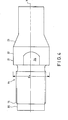
- Figure 4 is a top view of the conversion connector.
- Figure 1A shows a drill bit/rod combination of the Prior Art, which combination does not provide sufficient support of the drill bit for good-quality drillholes. For instance when the drilling resistance or the need of feeding force changes, the drill tends to deviate, and the narrow rod system does not provide sufficient support.
- Figure 1B shows a similar situation using a drill rod system in accord- ance with the invention. This figure illustrates only the drill bit section and the supporting tubular drill rod section attached to the drill bit section. The supporting rod section now prevents the drill hit from deviating, as the outer surface of the red, should deviating tendency occur, touches the wall of the finished drillhole even when the angular deviation of the drilling direction is small.
- Figure 1C shows a
drilling equipment combination 25 in accordance with the invention in a drilling situation. The cuttings rise from the bottom s of the drillhole toward the mouth section s of the drillhole. Larger stones or pieces of soil f cannot fall down to the bottom s3 of the drillhole, as the space between the wall s1 of the drillhole and supporting rod structure is narrow. - Figure 2 shows a
drill equipment combination 25 in accordance with the invention, comprising adrill bit 10 with itsshank section 11. Thedrill bit 10 is fastened by a threaded coupling to atubular drill rod 12. Saidtubular drill rod 12 is fastened to one end of aconversion connector 14 with a threaded joint; anotherdrill rod 13 essentially smaller in diameter than the supportingdrill rod 12 is fastened to the other end of saidconversion connector 14. - D1 denotes the diameter of a hole being drilled; D2 denotes the outer diameter of the drill bit; D3 denotes the outer diameter of the tubular drill rod fastened to the shaft of the bit at one end and to one end of the
conversion connector 14 at the other end. D4 denotes the largest diameter of the center section of theconversion connector 14, and D5 denotes the outer diameter of the rod fastened to the other end of the conversion connector with a threaded joint. - There might be 1 to 3 drill rods as required. The number of
drill rods 12 depends on their length, for instance. The lenght of one drill rod is preferably between 1500 to 6100 mm. - Diameters D2 to D4 as essentially equal to each other for smooth and stepless surface. The narrow outer flushing channel provides a suf- ficient flushing speed and consequently a sufficiently efficient removal of drilling dust and cuttings, and as this part of the rod system has an essentially smooth outer surface, there will be no constrictions which would impede the removal of drilling dust and cuttings and also have detrimental influence on consumption of energy by the flushing medium.
- Figure 2 also shows the
tubular rod 12 with a partial section view in order to show the central flushing channel. D6 denotes the diameter of the central flushing channel. In the middle of therod system 13 there is also a small-diameter flushing channel system which is not separately illustrated in the figure. - In order to provide adequate flushing and consequently good support the cross-section area of the central flushing channel of the
tubular drill bar 12 is made essentially equal to the cross-section area of the outer flushing channel. Then there will be no energy-wasting constrictions. ; Shaping the rod in the described manner also results in a relatively narrow outer flushing channel, whereat the speed of the flushing medium will be high enough, and also the structure will such as to keep the outer face of the drill rod very close to the wall of the drillhole being formed, which is a prerequisite of good support and minimum tilting of the drill rod in the drillhole. Now there will not be much room for the drill bar to bend in the drillhole; as the drill deviates from its original direction, the drill bar will touch the wall of the drill hole thus preventing the drill from deviating further. - Figure 3 shows a longitudinal section view of the
conversion connector 13 in an enlarged scale. The conversion connector is an elongated cylindrical piece, symmetrical as to its longitudinal axis. At one end it has athread 15 for fastening it to thetubular drill rod 12; at the other end it has athread 16 for fastening it to the smaller-diameter drill rod 13. Thethread 15 is preferably an external thread; thethread 16 is preferably an internal thread. Thethread 15 mate the end thread of thetubular drill rod 12, and it has been selected from a thread system in which the thread angle and the profile height h mainly remain constant independently of the outer diameter D of thetubular drill bar 12, wherat the pitch of the thread and the number of thread heads n increase as the outer diameter D of thetubular drill rod 12 increases. In the thread system in question the thread has been selected as follows: if the outer diameter D of thetubular drill rod 12 is smaller than 70 mm, the thread is one-headed and its pitch is less than 23 mm; if the outer diameter of thetubular drill rod 12 is 70 to 152 mm, the thread is two-headed and its pitch is 23 to 45 mm; if the outer diameter of thetubular drill rod 12 is over 152 mm, the thread is three-headed and its pitch is over 45 mm. - In said thread system, the pitch of the thread is 6° to 8°, preferably approx. 7°, and its profile height is 1.5 to 4 mm. The profile height could preferably be 2 to 3 mm. The flank angle a of the thread is 25° to 45°, preferably approx. 35°.
- On the other hand, the thread system of the
thread 16 may be chosen freely. - Thus the conversion connector makes the system flexible, as the
rods 13, whose thread may represent different thread systems, may, by means of theconversion connector 14, be easily connected to the tubular and supportingdrill rod 12. - In figure 3, showing a section view of the
conversion connector 14, there is acircular mating surface 17, against which the end of therod 13 is turned. Theconversion connector 14 also has aplane face 18, against which the end of therod 12 will lean. The specific object is that impact energy will be transmitted by these mating surfaces instead of the threads. When moving from the smaller-diameter drill rod 13 to the larger-diameter drill rod 12, the intention is to keep the steel cross-section constant in order to avoid reflection of impact energy. Approximately at the middle section of theconversion connector 14, in its flushing channel section, there is abevelled channel surface 19 which is aimed at maintaining said steel cross-section as constant as possible and at the same time at promoting the laminarity of the flow of the flushing medium as it flows to the wider flushing channel section of thedrill pipe 12. - In the outer-thread end of the
conversion connector 14 there is also a guidingsection 20 whose diameter is smaller than the bottom diameter of the threaded section; the object of this guidingsection 20 is, when therod 12 and theconversion connector 14 are fitted together, guide their threads to mate. In theconversion connector 14 there is acylindrical center part 21, which has wrench-flats 24 for opening with hand tools in those exceptional cases when the joint cannot be opened mechanically by shock by disconnecting the rotation movement and leaving the impact drive on. - Figure 4 shows a top view of the
conversion connector 14; said wrench- flat 24 can be seen in this figure. 22 denotes the mantle surface of themiddle section 21 of the connector. The diameter D4 of saidmiddle section 21 is essentially equal to the outer diameter D of thetubular drill rod 12. Abevelled surface 23 is bounded by themantle section 22. It runs obliquely downwards and promotes the laminarity of the flushing medium flow toward the mouth section of the drillhole.
Claims (13)
Applications Claiming Priority (2)
| Application Number | Priority Date | Filing Date | Title |
|---|---|---|---|
| FI850707 | 1985-02-20 | ||
| FI850707A FI850707A7 (en) | 1985-02-20 | 1985-02-20 | Drilling equipment intended for impact drilling. |
Publications (2)
| Publication Number | Publication Date |
|---|---|
| EP0192622A2 true EP0192622A2 (en) | 1986-08-27 |
| EP0192622A3 EP0192622A3 (en) | 1987-12-09 |
Family
ID=8520417
Family Applications (1)
| Application Number | Title | Priority Date | Filing Date |
|---|---|---|---|
| EP86850038A Withdrawn EP0192622A3 (en) | 1985-02-20 | 1986-02-07 | Drilling equipment for percussive drilling |
Country Status (2)
| Country | Link |
|---|---|
| EP (1) | EP0192622A3 (en) |
| FI (1) | FI850707A7 (en) |
Cited By (3)
| Publication number | Priority date | Publication date | Assignee | Title |
|---|---|---|---|---|
| CN104343390A (en) * | 2014-09-18 | 2015-02-11 | 平顶山市安泰华矿用安全设备制造有限公司 | Water conservancy reaming system |
| EP3023575A1 (en) | 2014-11-21 | 2016-05-25 | Sandvik Intellectual Property AB | Drill string rod with shoulder |
| US9759020B2 (en) | 2016-01-22 | 2017-09-12 | Atlas Copco Drilling Solutions, Llc | Rod and rod cup alignment apparatus for drilling machine |
Family Cites Families (5)
| Publication number | Priority date | Publication date | Assignee | Title |
|---|---|---|---|---|
| US3152458A (en) * | 1963-08-28 | 1964-10-13 | Pittsburgh Steel Co | Oil well drilling string |
| US3706348A (en) * | 1971-12-06 | 1972-12-19 | Shell Oil Co | Well deviation control system |
| US4310059A (en) * | 1980-01-21 | 1982-01-12 | Christensen, Inc. | Composite heavy metal drill collar |
| US4427079A (en) * | 1981-11-18 | 1984-01-24 | Walter Bruno H | Intermittently rotatable down hole drilling tool |
| FI68293B (en) * | 1982-11-30 | 1985-04-30 | Airam Ab Oy | FOERFARANDE I LAONGHAOLBERGBORRNING OCH BORRSTAONGSYSTEM |
-
1985
- 1985-02-20 FI FI850707A patent/FI850707A7/en not_active Application Discontinuation
-
1986
- 1986-02-07 EP EP86850038A patent/EP0192622A3/en not_active Withdrawn
Cited By (4)
| Publication number | Priority date | Publication date | Assignee | Title |
|---|---|---|---|---|
| CN104343390A (en) * | 2014-09-18 | 2015-02-11 | 平顶山市安泰华矿用安全设备制造有限公司 | Water conservancy reaming system |
| CN104343390B (en) * | 2014-09-18 | 2016-08-17 | 平顶山市安泰华矿用安全设备制造有限公司 | A kind of water conservancy reaming system |
| EP3023575A1 (en) | 2014-11-21 | 2016-05-25 | Sandvik Intellectual Property AB | Drill string rod with shoulder |
| US9759020B2 (en) | 2016-01-22 | 2017-09-12 | Atlas Copco Drilling Solutions, Llc | Rod and rod cup alignment apparatus for drilling machine |
Also Published As
| Publication number | Publication date |
|---|---|
| FI850707L (en) | 1986-08-21 |
| FI850707A7 (en) | 1986-08-21 |
| EP0192622A3 (en) | 1987-12-09 |
| FI850707A0 (en) | 1985-02-20 |
Similar Documents
| Publication | Publication Date | Title |
|---|---|---|
| US3870114A (en) | Drilling apparatus especially for ground drilling | |
| CA2221018C (en) | Straight hole drilling system | |
| US4278137A (en) | Apparatus for extracting minerals through a borehole | |
| EP0695390B1 (en) | Drilling kick-off device | |
| KR100841034B1 (en) | Drilling tools | |
| EP3023575A1 (en) | Drill string rod with shoulder | |
| CN101603411B (en) | Drilling rig and drilling method | |
| RU2629296C1 (en) | Guiding pipe for the formable bending drill rod | |
| US6732820B1 (en) | Method and apparatus for boring through a solid material | |
| WO2007133151A1 (en) | A rock-drilling tool, a drill rod and coupling sleeve | |
| HU205790B (en) | Drilling jig | |
| CA1173822A (en) | Apparatus for drilling straight portion of a deviated hole | |
| US7896108B2 (en) | Dual string orbital drilling system | |
| US4793740A (en) | Drilling system | |
| US4240512A (en) | Arrangement for guiding a bore-crown or bit along a given path | |
| NO312640B1 (en) | Installation in the lower part of the drill string | |
| EP4261383A1 (en) | Drill pipe cleaning system | |
| JP2000506575A (en) | Detachable guide for guiding drill string components in boreholes | |
| EP1175547A1 (en) | Percussion drilling apparatus and drilling tube | |
| US20060175093A1 (en) | Method and device for boring holes in soil or rock | |
| AU2003206573A1 (en) | Method and device for directional down-hole drilling | |
| US4303134A (en) | Earth boring guide | |
| RU2331751C2 (en) | Drill string for upward drilling and components | |
| EP0211926A1 (en) | Drilling pipe for making a drill string | |
| DE10006973A1 (en) | Displacement piledriver has vibrator downhole part of drillpipe as flexibly joined to surface part carrying drillpipe reciprocating rotation motor plus concreting pipe right through pipe. |
Legal Events
| Date | Code | Title | Description |
|---|---|---|---|
| PUAI | Public reference made under article 153(3) epc to a published international application that has entered the european phase |
Free format text: ORIGINAL CODE: 0009012 |
|
| AK | Designated contracting states |
Kind code of ref document: A2 Designated state(s): AT BE CH DE FR GB IT LI LU NL SE |
|
| RAP1 | Party data changed (applicant data changed or rights of an application transferred) |
Owner name: KOMETA OY |
|
| PUAL | Search report despatched |
Free format text: ORIGINAL CODE: 0009013 |
|
| AK | Designated contracting states |
Kind code of ref document: A3 Designated state(s): AT BE CH DE FR GB IT LI LU NL SE |
|
| STAA | Information on the status of an ep patent application or granted ep patent |
Free format text: STATUS: THE APPLICATION IS DEEMED TO BE WITHDRAWN |
|
| 18D | Application deemed to be withdrawn |
Effective date: 19880613 |
|
| RIN1 | Information on inventor provided before grant (corrected) |
Inventor name: VESTMAN, MATTI |