EP0192490B1 - Time-domain intensity normalization for fiber optic sensing - Google Patents
Time-domain intensity normalization for fiber optic sensing Download PDFInfo
- Publication number
- EP0192490B1 EP0192490B1 EP86301256A EP86301256A EP0192490B1 EP 0192490 B1 EP0192490 B1 EP 0192490B1 EP 86301256 A EP86301256 A EP 86301256A EP 86301256 A EP86301256 A EP 86301256A EP 0192490 B1 EP0192490 B1 EP 0192490B1
- Authority
- EP
- European Patent Office
- Prior art keywords
- signal
- intensity
- receiver
- transducer
- fibre
- Prior art date
- Legal status (The legal status is an assumption and is not a legal conclusion. Google has not performed a legal analysis and makes no representation as to the accuracy of the status listed.)
- Expired - Lifetime
Links
- 239000000835 fiber Substances 0.000 title claims abstract description 9
- 238000010606 normalization Methods 0.000 title description 3
- 230000003287 optical effect Effects 0.000 claims abstract description 93
- 230000003111 delayed effect Effects 0.000 claims abstract description 18
- 230000000737 periodic effect Effects 0.000 claims description 4
- 239000013307 optical fiber Substances 0.000 abstract description 24
- 238000012545 processing Methods 0.000 abstract description 24
- 239000002131 composite material Substances 0.000 description 37
- 238000010586 diagram Methods 0.000 description 11
- 230000000694 effects Effects 0.000 description 8
- 230000001902 propagating effect Effects 0.000 description 8
- 238000013459 approach Methods 0.000 description 4
- 238000000034 method Methods 0.000 description 4
- 239000000284 extract Substances 0.000 description 3
- 230000007246 mechanism Effects 0.000 description 3
- 230000002238 attenuated effect Effects 0.000 description 2
- 230000005540 biological transmission Effects 0.000 description 2
- 230000008859 change Effects 0.000 description 2
- 230000001066 destructive effect Effects 0.000 description 2
- 238000001514 detection method Methods 0.000 description 2
- 238000012986 modification Methods 0.000 description 2
- 230000004048 modification Effects 0.000 description 2
- 238000006467 substitution reaction Methods 0.000 description 2
- 230000001360 synchronised effect Effects 0.000 description 2
- 230000000295 complement effect Effects 0.000 description 1
- 239000000470 constituent Substances 0.000 description 1
- 238000010276 construction Methods 0.000 description 1
- 230000008878 coupling Effects 0.000 description 1
- 238000010168 coupling process Methods 0.000 description 1
- 238000005859 coupling reaction Methods 0.000 description 1
- 230000007423 decrease Effects 0.000 description 1
- 230000003292 diminished effect Effects 0.000 description 1
- 238000001914 filtration Methods 0.000 description 1
- 239000012530 fluid Substances 0.000 description 1
- 238000010348 incorporation Methods 0.000 description 1
- 238000004519 manufacturing process Methods 0.000 description 1
- 238000005259 measurement Methods 0.000 description 1
- 230000008569 process Effects 0.000 description 1
- 230000008054 signal transmission Effects 0.000 description 1
- 238000011144 upstream manufacturing Methods 0.000 description 1
Images


Classifications
-
- G—PHYSICS
- G01—MEASURING; TESTING
- G01D—MEASURING NOT SPECIALLY ADAPTED FOR A SPECIFIC VARIABLE; ARRANGEMENTS FOR MEASURING TWO OR MORE VARIABLES NOT COVERED IN A SINGLE OTHER SUBCLASS; TARIFF METERING APPARATUS; MEASURING OR TESTING NOT OTHERWISE PROVIDED FOR
- G01D5/00—Mechanical means for transferring the output of a sensing member; Means for converting the output of a sensing member to another variable where the form or nature of the sensing member does not constrain the means for converting; Transducers not specially adapted for a specific variable
- G01D5/26—Mechanical means for transferring the output of a sensing member; Means for converting the output of a sensing member to another variable where the form or nature of the sensing member does not constrain the means for converting; Transducers not specially adapted for a specific variable characterised by optical transfer means, i.e. using infrared, visible, or ultraviolet light
- G01D5/32—Mechanical means for transferring the output of a sensing member; Means for converting the output of a sensing member to another variable where the form or nature of the sensing member does not constrain the means for converting; Transducers not specially adapted for a specific variable characterised by optical transfer means, i.e. using infrared, visible, or ultraviolet light with attenuation or whole or partial obturation of beams of light
- G01D5/34—Mechanical means for transferring the output of a sensing member; Means for converting the output of a sensing member to another variable where the form or nature of the sensing member does not constrain the means for converting; Transducers not specially adapted for a specific variable characterised by optical transfer means, i.e. using infrared, visible, or ultraviolet light with attenuation or whole or partial obturation of beams of light the beams of light being detected by photocells
- G01D5/353—Mechanical means for transferring the output of a sensing member; Means for converting the output of a sensing member to another variable where the form or nature of the sensing member does not constrain the means for converting; Transducers not specially adapted for a specific variable characterised by optical transfer means, i.e. using infrared, visible, or ultraviolet light with attenuation or whole or partial obturation of beams of light the beams of light being detected by photocells influencing the transmission properties of an optical fibre
- G01D5/35303—Mechanical means for transferring the output of a sensing member; Means for converting the output of a sensing member to another variable where the form or nature of the sensing member does not constrain the means for converting; Transducers not specially adapted for a specific variable characterised by optical transfer means, i.e. using infrared, visible, or ultraviolet light with attenuation or whole or partial obturation of beams of light the beams of light being detected by photocells influencing the transmission properties of an optical fibre using a reference fibre, e.g. interferometric devices
Definitions
- This invention relates to fiber optic sensing systems wherein a sensor is interposed in the system between a light source and a receiver and wherein the sensor is responsive to a parameter to alter the intensity of the light passing therethrough.
- Fiber optic sensing systems generally utilize a sensor inter-connected by optical waveguides between a light source and a receiver.
- the sensor includes one or more transducers that respond to an external parameter, for example ambient pressure, to vary the intensity of an optical signal that is generated by the light source for propagation through the system.
- an external parameter for example ambient pressure
- An example of a typical application would be one in which a transducer attenuates the intensity of the light signal in inverse proportion to the magnitude of the parameter.
- the receiver detects the change in intensity of the signal. Suitable processing circuitry then produces an indication of the magnitude of the parameter.
- the intensity of the light that propagates through the system is not varied solely by the transducer in the sensor. That is, numerous other factors tend to vary the intensity of the propagating light. The most significant of these factors include: variations in light source intensity; connector losses; and, fiber path losses. These factors are inherent in the construction of the system and their effects will vary with the age of the system and changes in the environment surrounding the system. For accurate determination of the intensity variation caused solely by the transducer(s) it is necessary to compensate for the additional intensity variations caused by these other factors.
- the receiver should be provided with a reference signal that propagates along an optical path that is separate from the path of the signal whose intensity is varied by the transducer (the latter signal hereinafter referred to as the "sensed signal").
- This separate optical path which allows the reference signal to be distinguished from the sensed signal, is defined by an optical waveguide that is constructed to be substantially identical to the sensed signal optical waveguide except that it bypasses the transducer. That is, the length, connectors and other elements of the reference waveguide match, as nearly as possible, those corresponding elements of the sensed signal waveguide.
- both the reference and sensed signals should undergo substantially identical intensity variations caused by the above described factors.
- the reference signal bypasses the transducer, thus its intensity is not further varied by the transducer. Normalizing the sensed signal intensity (i.e. taking a simple ratio of the sensed signal to the reference signal) will yield the dimensionless value of intensity variation caused by the transducer irrespective of the intensity variations caused by the other factors.
- a problem with the just described compensation method is that with the present state of the art it is extremely difficult to precisely match optical paths for duplicating all intensity-varying factors.
- the decoupling and remating of a single connector may cause a change in the transmitted intensity by as much as 50%.
- a transducer having an accuracy on the order of 0.1% it can be appreciated that when attempting to match waveguides that employ several connectors, a rather significant opportunity for error is introduced each time a connection is decoupled and remated.
- short radius bends (less than 5 centimeter bend radius) can introduce attenuation on the order of several percent in an optical waveguide.
- the reference signal waveguide and the sensed signal waveguide are not properly matched, or if after matching, one of the waveguides is bent, disconnected and remated, or otherwise moved relative to the other waveguide, then the resulting normalization of the sensed signal intensity will not accurately reflect the intensity variation caused solely by the transducer.
- US 4,182,935 discloses a fibre-optic sensing system comprising an optical signal source providing a signal on a fibre-optic waveguide, a splitter dividing the signal along first and second paths of different optical lengths whereby one portion is delayed with respect to the other, a coupler combining the signal portions on to a single path, and a signal receiver.
- the invention provides a fibre-optic sensing system as disclosed in US 4,182,935, characterised in that a transducer of a kind capable of measuring a continuously variable parameter is included in at least one of the first and second paths, the signal from the receiver is processed by a signal processor including separating means for separating the delayed signal portion from the undelayed signal portion, and a divider for dividing one signal portion by the other to obtain an output signal representing the ratio of their amplitudes, as claimed in claim 1
- the invention provides a fibre-optic sensing system as disclosed in US 4,182,935, characterised in that a transducer of a kind capable of measuring a continuously variable parameter is included in at least one of the first and second paths, said signal source is arranged to generate an optical signal having a periodic component, the delay introduced by the difference in optical lengths of said paths is selected to cause interference between the delayed and undelayed portions of the periodic component of said signal and the signal from the receiver is processed by a signal processor including filter means arranged to separate two components of the received signal and to apply the sum and difference of said components to the respective inputs of a divider to obtain an output signal representing the ratio of said sum and difference, as claimed in claim 4.
- the invention generally provides a fibre-optic sensing system that overcomes the above-noted problems in the prior art by employing a reference signal, distinguishable in the time domain from the sensed signal, that propagates along substantially the same path as the sensed signal such that the relationship between the reference and the sensed signal is independent of other variation factors.
- the system formed in accordance with this invention obviates the need for matching several separate waveguide elements.
- the determination of the intensity variation caused by the transducer is unaffected by other intensity varying factors since both the reference and sensed signals are identically influenced by those factors.
- light source 10 which is modulated by oscillator 11, generates a pulsed source optical signal 12 (indicated by an arrow in the figure) for propagation along a connected main optical waveguide 14.
- the light source 10 that generates the pulsed source signal may be a light-emitting diode or other suitable optical source constructed by techniques well known in the art.
- the main optical waveguide 14 is a single optical fiber and can be of any desired length. It is understood that main optical waveguide 14 can also be formed from a bundle of optical fibers. In any event, the main optical waveguide 14 provides a single optical path for propagation of the source optical signal 12.
- FIGURE 2 Shown in FIGURE 2 is a diagram of a single pulse source signal 12 of intensity I as observed at a point along main optical waveguide 14.
- the source signal 12 is generated with intensity I o , which may vary due to uncontrollable variations in the structure of energy supply of the light source 10. Nevertheless, as will be understood upon reading this description, such variation will be compensated in the processing circuitry of the system formed in accordance with this invention.
- the main optical waveguide 14 terminates within a sensor unit 16. Specifically, within the sensor unit 16 the main optical waveguide 14 is connected to a splitter 18 that splits the source signal into two component signals 20 and 22 (also indicated by arrows) for propagation along respective branch optical waveguides 24 and 26, which are connected at their input ends 23 to the splitter 18. Like the main optical waveguide 14, branch optical waveguides 24 and 26 are also formed of single optical fibers or fiber bundles.
- component signal 20 can be represented by I s and the intensity of component signal 22 can be represented by I r .
- component signal 20 is the sensed signal; component signal 22 is the reference signal.
- the source signal 12 that propagates along main optical waveguide 14 is subject to a variety of factors that tend to vary its intensity.
- the connectors used for securing the optical waveguide to the light source 10 the connectors used along the waveguide, and the splitter 18 will all, in some measure, attenuate the intensity of light propagating through the waveguide.
- the optical waveguide itself will attenuate the intensity of light transmitted through it. The degree of attenuation depends upon the length, environment, configuration, and age of the waveguide.
- the component signals 20 and 22 are formed by splitting the source signal 12, their intensities I s and I r , respectively, will proportionately share the above-mentioned intensity variation of the source signal 12.
- the actual values of the component signal intensities will depend upon how the source signal 12 is split.
- the splitter 18 may be adjustable so that its splitting function ⁇ can be set at any desired value. In the preferred embodiment, the splitting function ⁇ is set at 0.50.
- component signals 20 and 22 begin propagation from splitter 18 with intensities I s and I r , respectively, that are equal to each other, having the value (1/2)( ⁇ 'I o ).
- ⁇ ' ⁇ ' represents the collection of factors responsible for the variation of the source signal's intensity as it propagates from the source through the splitter; the value of ⁇ ' being a dimensionless fraction, which when multiplied by the source signal intensity yields the value of that signal intensity as attenuated by those factors.
- Transducer 28 can be any mechanism (such as microbending, macrobending, varying density, etc.) that is responsive to an external parameter (for example, temperature, pressure, fluid levels, etc.) and is capable of varying the intensity of the propagating light in some functional relationship with the parameter magnitude.
- transducer 28 attenuates the intensity I s of component signal 20 in inverse proportion to the magnitude of the parameter being sensed.
- component signal 20 exits transducer 28 with its intensity attenuated by an amount corresponding to transducer variation fuction ⁇ . Accordingly, the intensity I s of the component signal 20, after passing through transducer 28, is represented by ( ⁇ /2)( ⁇ 'I o ). (0 ⁇ 1).
- the other component signal 22 propagates along branch optical waveguide 26.
- component signal 22 is used as a reference signal for the hereinafter described processing. In order for this signal to be utilized, however, it is necessary to distinguish it from the component signal 20 that is affected by transducer 28.
- a delay optical fiber 30 is incorporated into branch optical waveguide 26 for the purpose of delaying the propagation of the associated component signal 22 relative to that of component signal 20.
- the delay optical fiber 30 is simply a length of optical fiber, preferably formed into a coil.
- delay optical fiber 30 may cause some attenuation of the intensity I r of the reference signal.
- any such attenuation may be compensated for by the incorporation of any suitable attenuation device (e.g., fixed gap or microbending) into the splitter 18 to cause a corresponding attenuation (absent a significant delay in propagation) in the intensity I s of the sensed signal 20. It is recognized that this single loss matching requirement can also be readily accomplished by alternative means such as by adjusting the splitting function accordingly. In any event, these matched losses will hereinafter be considered as included in the earlier described intensity variation factors symbolized as ⁇ '.
- the branch optical waveguides 24 and 26 converge and are connected at their output ends 25 to a return optical waveguide 34 by a coupler 32.
- the undelayed component signal 20 and the delayed component signal 22 thus emerge from the sensor unit 16 and propagate along the return optical waveguide 34.
- the intensity of the component signals 20 and 22 are represented as they are observed at a point on the return optical waveguide 34.
- t d represents the duration of the delay caused by delay optical fiber 30.
- t d is greater than or equal to the duration of each component signal 20 and 22, hence the signals propagate as discrete pulses along return optical waveguide 34. If t d is less than the duration of each component signal, the signals will propagate along the return optical waveguide 34 in a configuration as represented in FIGURE 4.
- the intensities I s and I r are still identifiable and can be processed in a manner as hereinafter described.
- FIGURE 5 illustrates the component signals 20 and 22 as they would propagate on the return optical waveguide 34 if a modification is made to the preferred embodiment of FIGURE 1.
- delay optical fiber 30 can alternatively be incorporated into branch optical waveguide 24 to delay component signal 20 instead of component signal 22.
- component signal 22 will merely travel ahead of component signal 20 along the return optical waveguide 34. The relative position of these signals has no significant affect on the subsequent processing of them.
- return optical waveguide 34 is connected between the coupler 32 and a receiver 36. It is pointed out that the return optical waveguide 34, like main optical waveguide 14, is formed of either a single optical fiber or bundle of fibers to provide a single optical path. Hence, component signals 20 and 22 that propagate along the return optical waveguide 34 will both be subject to intensity-varying factors defined as ⁇ '' as these signals travel through the coupler 32, along return optical waveguide 34 and into the receiver 36. It is also pointed out that since return optical waveguide 34 provides a single optical path, component signals 20 and 22 will be identically affected by those intensity-varying factors ⁇ ''.
- Receiver 36 which utilizes a single channel, incorporates a photo-detector, amplifier and appropriate circuitry for detecting component signals 20 and 22 and converting them into representative electrical signals.
- Such circuitry forms no part of this invention and is readily designed by those skilled in the art.
- the electrical signals representative of component signals 20 and 22 (and their corresponding intensities I s and I r ) are transmitted to signal processing circuitry.
- the signal processing circuitry 38 consists of sample and hold circuits 42 and 44 operatively associated with gate control 46.
- Gate control 46 generates signals corresponding to the sensed and reference pulses emanating from receiver 36 that are synchronized with those pulses to cause acceptance (by conventional gating mechanisms) of each pulse by its appropriate sample and hold circuit 42 or 44.
- the value of the transducer variation function ⁇ and/or the related magnitude of the parameter is displayed or recorded on a suitable output device 40.
- the light source 10 can be oscillated to produce a continuous wave source signal.
- the reference and sensed signals do not propagate as discrete signals but are constituent portions of a continuous composite waveform that is formed by the coupler in the sensor unit.
- the hereinafter-described processing of the composite signal extracts the appropriate portions of the composite signal to construct sensed and reference signals and then normalize the former with respect to the latter.
- light source 110 is modulated by oscillator 111 so that source signal 112 is a continuous wave signal.
- source signal 112 is a continuous wave signal.
- a pure sine wave will be discussed; however, the principles apply likewise to any modulated wave.
- a fully modulated wave having a 50% duty cycle is utilized in order to avoid the need for any waveform compensation mechanisms.
- the light source 110 is modulated so that the period T of the resulting wave is equal to twice the delay duration t d of the delay optical fiber 130.
- the continuous wave source signal 112 passes through the splitter 118 (with the splitter function ⁇ equal to 0.50), where the signal is formed into two component signals 120 and 122, each being described by its AC and DC portions as: (1/2)(I a ⁇ ' cos ⁇ t + I a ⁇ ') where I a is equal to the average value of the modulated source intensity and, as before, ⁇ ' represents the collection of factors responsible for the variation of the source signal's intensity as it propagates from the source through the splitter.
- AC portion and DC portion herein used in the context of optical signal transmissions, refer to the time-varying magnitude and time-average values of the signal respectively.
- this alternative embodiment utilizes essentially the same sensor unit structure 16 as the preferred embodiment. As shown in FIGURE 7, however, the delay optical fiber 130 is incorporated into branch optical waveguide 120. As noted earlier, the location of the delay optical fiber will not significantly affect subsequent processing.
- I' s ( ⁇ /2)( I a ⁇ ' cos( ⁇ (t - t d )) + I a ⁇ ').
- the period T of the continuous wave source signal 112 (hence the period of each component signal 120 and 122) is selected to be equal to twice the delay duration t d of the delay optical fiber 130.
- a relative delay of T/2 or one half cycle (expressed as ⁇ radians), is experienced by the component signal 120.
- I' r (1/2)(I a ⁇ ' cos( ⁇ t) + I a ⁇ ').
- the effect of this addition is to cancel out the transducer effect since any diminution of the AC portion caused by the variation function of the transducer (through the above-noted destructive interference) is offset by a corresponding increase in the value of the DC portion (through the above-noted constructive interference).
- a sensed signal intensity is derived by subtracting the AC portion of the combined signal from the DC portion.
- the resulting value includes the effects of the transducer variation function ⁇ and, of course, other intensity varying factors common to both the sensed and reference signals.
- FIGURE 7 illustrates the processing circuitry employed for accomplishing the normalization for this embodiment.
- the composite signal 148 shown by the wavy arrow in FIGURE 7, exits coupler 132 and propagates along the return optical waveguide 134.
- the composite signal 148 will be subject to intensity varying factors ⁇ '' as it travels through the coupler and along return optical waveguide 134 and into receiver 136.
- the composite signal 148 branches into band-pass filter 150 and low-pass filter 152.
- Band-pass filter 150 which is tuned to the frequency of the modulated light source 110, extracts the AC portion from the composite signal.
- the AC portion is then routed through AC detector 154 wherein the signal having peak magnitude v(1- ⁇ ) is extracted.
- Low-pass filter 152 extracts the DC portion, having magnitude v(1+ ⁇ ), from the composite signal.
- the AC and DC portions are added in sum circuit 156 to create a reference signal having magnitude 2v.
- the AC portion is subtracted from the DC portion in difference circuit 158 to create a sensed signal of magnitude 2v ⁇ .
- the sensed signal is normalized by determining the ratio of the sensed to reference signal or which yields ⁇ , the transducer variation function which is then displayed and/or recorded on output device 140.
- the above-described continuous wave embodiment requires a receiver responsive to the DC or time-average portion of the composite signal without incurring DC drift.
- the oscillating source signal can be modified to create an additional AC portion of the continuous wave signal that is distinguishable from the original AC portion of that signal. With two such distinct AC portions, the need for detecting and processing the DC portion of the signal is obviated.
- the above-mentioned distinct AC portions of the optical source signal are created by the inclusion of oscillator signal processing circuitry 260 between oscillator 211 and light source 210.
- the continuous wave oscillator signal at frequency f1 is applied to parallel branches 262 and 264 of circuitry 260.
- Frequency f1 is such that its period is equal to twice the duration of the delay t d of the delay optical fiber 230.
- frequency f1 is unaltered.
- frequency f1 is doubled (which results in its period equalling t d ) by frequency doubler circuitry 266 so as to result in frequency f2.
- frequency f2 can alternatively be formed by an independent oscillator.
- frequency f2 can be formed to be any even harmonic of frequency f1 (i.e., 2f1, 4f1, 6f1, etc.).
- both frequencies preferably have matched amplitudes thereby obviating the need for incorporating additional compensation in the signal processing circuitry.
- both frequencies are combined into a single signal upstream of the modulated light source 210 such that the resulting source optical signal 212 propagates through the system as a continuous composite waveform formed by the addition of the two oscillator signals having frequencies f1 and f2, which have distinguishable AC portions.
- I s '' ( ⁇ /2)I a ⁇ ' cos( ⁇ (t-t d ))+( ⁇ /2)I a ⁇ ' cos(2 ⁇ (t-t d )).
- the first term, ( ⁇ /2)I a ⁇ ' cos( ⁇ (t-t d )) is representative of the AC portion of the composite signal that is defined by frequency f1 and has a period equal to 2t d .
- the second term, ( ⁇ /2)I a ⁇ ' cos(2 ⁇ (t-t d )), is representative of the AC portion of the composite signal that is defined by frequency f2 that has a period equal to t d .
- the portion of the signal represented by the first term is delayed one half cycle or ⁇ radians
- the portion of the signal represented by the second term is delayed a full cycle or 2 ⁇ radians.
- I'' r (1/2)I a ⁇ ' cos( ⁇ t)+(1/2)I a ⁇ ' cos(2 ⁇ t).
- the first term of the above expression due to the one-half cycle delay, includes any destructive interference effects (as evidenced by the (1 - ⁇ ) term).
- the second term of the expression includes the effects of the constructive interference since that portion of the composite wave was delayed a full cycle. Therefore, as developed earlier, composite wave was delayed a full cycle. Therefore, as developed earlier, addition of the first and second term (after filtering and detection) will yield a signal unaffected by the variation function ⁇ of the transducer, i.e., a reference signal. Subtracting the first term from the second term will yield a signal that includes the effects of ⁇ .
- the processing circuitry 238 for this embodiment is also shown in FIGURE 8, wherein the composite signal 248 is converted in receiver 236 from an optical signal to a representative electrical signal and then branched through parallel band-pass filters 266 and 268.
- Band-pass filter 266 is tuned to extract the portion of the signal having frequency f1 and represented by the term v(1 - ⁇ )cos( ⁇ t).
- Band-pass filter 268 is tuned to extract the portion of the signal having frequency f2 and represented by the term v(1 + ⁇ )cos(2 ⁇ t).
- Parallel AC detectors 270 and 272 detect the peak magnitude values of their associated signals v(1 - ⁇ ) and v(1 + ⁇ ) respectively.
- the output, v(1 - ⁇ ), of AC detector 270 is added to the output, v(1 + ⁇ ), of AC dectector 272, in sum circuit 256, yielding a reference signal of magnitude 2v.
- the output of AC detector 270 is subtracted from the output of AC detector 272 in difference circuit 258 to yield a sensed signal of magnitude 2v ⁇ .
- the sensed and reference signals are then divided in the divider circuitry 257 to yield the variation function of the transducer ⁇ .
- timing circuitry 275 includes gate control for the sample and hold circuits 280 and 282.
- the signal having frequency f2, and period equal to t d was added to the signal having frequency f1 to create a composite waveform optical signal with distinguishable AC portions -- thereby eliminating the need for a receiver sensitive to the DC portion of the composite signal.
- this low frequency of the composite waveform will be substantially unaffected by the delay imparted by the delay optical fiber. The significance of using such a low frequency is best understood upon reading the following description which follows the mathematical treatment offered earlier.
- electrical signal f h generated by oscillator 311 and having an amplitude K h is itself modulated by electrical signal f l , which is generated by oscillator 313 and has amplitude K l .
- the resulting signal f h f l described by its AC and DC portions is: (K h cos( ⁇ h t) + K h )(K l cos( ⁇ l t) + K l ) or K h K l (cos( ⁇ h t)cos( ⁇ l t) + cos( ⁇ h t) + cos( ⁇ l t) + 1) as before, the DC or time-average portion can be ignored.
- K defined as K h K l and using a standard trigonometric identity the resulting signal is: K((1/2)cos( ⁇ h - ⁇ l )t+(1/2)cos( ⁇ h + ⁇ l )t + cos ⁇ h t + cos ⁇ l t).
- This expression describes the electrical signal that modulates light source 310 to produce source optical signal 312. It is noted that the above described technique of creating the signal avoids the need for matching amplitudes K h and K l , which would be necessary if the signals of frequencies f h end f l are merely added. Rewriting the above expression in terms of the average value of the modulated source intensity I a yields the mathematical description of the optical signal propagating from light source 310: I a cos( ⁇ h t) + I a cos( ⁇ l t).
- the first term represents the AC portion of the composite signal that is defined by frequency f h .
- the second term represents the AC portion of the composite signal that is defined by frequency f l .
- I s ''' ( ⁇ /2)I a ⁇ 'cos( ⁇ h (t-t d ))+( ⁇ /2)I a ⁇ 'cos( ⁇ 1(t-t d )).
- the frequency f h is selected so that the period of the portion of the signal having frequency f h (i.e., the first term of the above expression) is equal to 2t d .
- this portion of the signal is delayed one-half cycle or ⁇ radians due to propagation through delay optical fiber 330.
- the frequency f l is selected so that its period is very long with respect to the duration of delay t d .
- f l f h /100
- band-pass filters 366 and 368 are tuned to frequencies f h and f l respectively. Hence processing of this above signal to yield the value of the transducer variation function ⁇ is accomplished in a manner substantially identical to that described in the embodiment depicted in FIGURE 8 and will not be repeated here.
- sensor unit 16 can also be modified so that branch optical waveguide 24 and branch optical waveguide 26 terminate at mirrors or other reflective elements 84.
- the component signals are therefore reflected back to the splitter/coupler 19 where they are recombined onto the main optical waveguide 14 and travel as combined reflected signal 86.
- a splitter 88 directs the combined signal from the main optical waveguide to receiver 36 and the processing circuitry. This approach eliminates the need for a separate return optical waveguide extending between the sensor and receiver.
- transducer 428 is a differential type transducer wherein as the attenuation of the intensity of the signal in branch optical waveguide 424 increases, the attenuation in branch optical waveguide 426 decreases in complementary fashion.
- the DC portion of the composite signal is independent of the transducer variation function ⁇ , thus the value of the DC portion after passing through low-pass filter 452 is used as a reference signal.
- the AC portion, variable with ⁇ is treated as the sensed signal.
- the AC portion is isolated in band-pass filter 450 and then passes through AC detector 454 which yields its peak value: (2v ⁇ -v).
- This sensed value (2v ⁇ -v) is then normalized with respect to the reference value v by the simple ratio operation performed by the divider circuitry 457.
- the output value of the divider circuitry (2 ⁇ -1) is a function of ⁇ , independent of any intensity variation factors and can be further processed to yield ⁇ and/or the value of the sensed parameter.
- sensor units 116, 216, 316 and 416 can employ more than one transducer or delay optical fiber with at least one distinguishable reference signal propagating through the sensor unit unaffected by a transducer for comparison with any of the sensed signals.
- the duration t d of any one delay must be unequal to the duration of any other so that all component signals can be distinguished by the receiver.
- an array of sensor units can be couples to the main optical waveguide wherein the sensed and reference signals are multiplexed onto the return optical waveguide (or onto the main optical waveguide if a reflective approach is used as discussed earlier with reference to FIGURE 11) and then demultiplexed and processed as before.
Landscapes
- Physics & Mathematics (AREA)
- General Physics & Mathematics (AREA)
- Optical Transform (AREA)
- Investigating Or Analysing Materials By Optical Means (AREA)
- Multicomponent Fibers (AREA)
- Photometry And Measurement Of Optical Pulse Characteristics (AREA)
Abstract
Description
- This invention relates to fiber optic sensing systems wherein a sensor is interposed in the system between a light source and a receiver and wherein the sensor is responsive to a parameter to alter the intensity of the light passing therethrough.
- Fiber optic sensing systems generally utilize a sensor inter-connected by optical waveguides between a light source and a receiver. The sensor includes one or more transducers that respond to an external parameter, for example ambient pressure, to vary the intensity of an optical signal that is generated by the light source for propagation through the system. An example of a typical application would be one in which a transducer attenuates the intensity of the light signal in inverse proportion to the magnitude of the parameter. The receiver detects the change in intensity of the signal. Suitable processing circuitry then produces an indication of the magnitude of the parameter.
- The intensity of the light that propagates through the system is not varied solely by the transducer in the sensor. That is, numerous other factors tend to vary the intensity of the propagating light. The most significant of these factors include: variations in light source intensity; connector losses; and, fiber path losses. These factors are inherent in the construction of the system and their effects will vary with the age of the system and changes in the environment surrounding the system. For accurate determination of the intensity variation caused solely by the transducer(s) it is necessary to compensate for the additional intensity variations caused by these other factors.
- In order to provide proper compensation for the intensity variations that are caused by factors other than the transducer, it has been recognized in the prior art that the receiver should be provided with a reference signal that propagates along an optical path that is separate from the path of the signal whose intensity is varied by the transducer (the latter signal hereinafter referred to as the "sensed signal"). This separate optical path, which allows the reference signal to be distinguished from the sensed signal, is defined by an optical waveguide that is constructed to be substantially identical to the sensed signal optical waveguide except that it bypasses the transducer. That is, the length, connectors and other elements of the reference waveguide match, as nearly as possible, those corresponding elements of the sensed signal waveguide. The separate optical path for the reference signal also necessitates the use of matched separate receiver channels with their associated connectors. By matching the waveguide elements, both the reference and sensed signals should undergo substantially identical intensity variations caused by the above described factors. As noted, the reference signal bypasses the transducer, thus its intensity is not further varied by the transducer. Normalizing the sensed signal intensity (i.e. taking a simple ratio of the sensed signal to the reference signal) will yield the dimensionless value of intensity variation caused by the transducer irrespective of the intensity variations caused by the other factors.
- A problem with the just described compensation method is that with the present state of the art it is extremely difficult to precisely match optical paths for duplicating all intensity-varying factors. To give an example, for a typical optical signal path, the decoupling and remating of a single connector may cause a change in the transmitted intensity by as much as 50%. Where it is desirable to employ a transducer having an accuracy on the order of 0.1% it can be appreciated that when attempting to match waveguides that employ several connectors, a rather significant opportunity for error is introduced each time a connection is decoupled and remated. Furthermore, short radius bends (less than 5 centimeter bend radius) can introduce attenuation on the order of several percent in an optical waveguide. Thus, if the reference signal waveguide and the sensed signal waveguide are not properly matched, or if after matching, one of the waveguides is bent, disconnected and remated, or otherwise moved relative to the other waveguide, then the resulting normalization of the sensed signal intensity will not accurately reflect the intensity variation caused solely by the transducer.
- In an article entitled "Optical system and sensors for measurement and control" by B. Culshaw, in Journal of Physics and Scientific Instruments vol. 16 no. 10, October 1983 pages 978-986 a number of different optical fibre transducers are described. It is stated in connection with some of the described systems that a reference channel is required. However, no details are given of any reference signal.
- US 4,182,935 discloses a fibre-optic sensing system comprising an optical signal source providing a signal on a fibre-optic waveguide, a splitter dividing the signal along first and second paths of different optical lengths whereby one portion is delayed with respect to the other, a coupler combining the signal portions on to a single path, and a signal receiver.
- In one aspect the invention provides a fibre-optic sensing system as disclosed in US 4,182,935, characterised in that a transducer of a kind capable of measuring a continuously variable parameter is included in at least one of the first and second paths, the signal from the receiver is processed by a signal processor including separating means for separating the delayed signal portion from the undelayed signal portion, and a divider for dividing one signal portion by the other to obtain an output signal representing the ratio of their amplitudes, as claimed in
claim 1 - In another aspect, the invention provides a fibre-optic sensing system as disclosed in US 4,182,935, characterised in that a transducer of a kind capable of measuring a continuously variable parameter is included in at least one of the first and second paths, said signal source is arranged to generate an optical signal having a periodic component, the delay introduced by the difference in optical lengths of said paths is selected to cause interference between the delayed and undelayed portions of the periodic component of said signal and the signal from the receiver is processed by a signal processor including filter means arranged to separate two components of the received signal and to apply the sum and difference of said components to the respective inputs of a divider to obtain an output signal representing the ratio of said sum and difference, as claimed in claim 4.
- Thus the invention generally provides a fibre-optic sensing system that overcomes the above-noted problems in the prior art by employing a reference signal, distinguishable in the time domain from the sensed signal, that propagates along substantially the same path as the sensed signal such that the relationship between the reference and the sensed signal is independent of other variation factors. The system formed in accordance with this invention obviates the need for matching several separate waveguide elements. Thus, the determination of the intensity variation caused by the transducer is unaffected by other intensity varying factors since both the reference and sensed signals are identically influenced by those factors.
- Embodiments of the invention are described below by way of example only with reference to the accompanying drawings.
-
- FIGURE 1 is a block diagram of a fiber-optic sensor system made in accordance with this invention;
- FIGURE 2 is a diagram of the source optical signal as it propagates between the light source and the sensor unit;
- FIGURE 3 is a diagram showing one configuration of the reference and sensed signals propagating between the sensor unit and the receiver;
- FIGURE 4 is a diagram showing another configuration of the propagation of the signals of FIGURE 3 wherein the sensed and reference signals overlap;
- FIGURE 5 is a diagram showing still another configuration of the propagation of the signals of FIGURE 3 wherein the sensed signal is delayed relative to the reference signal;
- FIGURE 6 is a diagram of the circuitry for the signal processing used to process the signals emanating from the sensor of the preferred embodiment;
- FIGURE 7 is a block diagram of an alternative embodiment of this invention wherein the light source is oscillated to produce a continuous wave optical signal;
- FIGURE 8 is another alternative embodiment of this invention showing the circuitry for producing and processing a modified continuous wave optical signal;
- FIGURE 9 illustrates alternative means for producing and processing a modified continuous wave optical signal;
- FIGURE 10 is a block diagram of an alternative embodiment of this invention wherein the signal producing the continuous wave optical signal is itself modulated prior to such production;
- FIGURE 11 is a diagram of an alternative embodiment for this invention employing reflective devices to direct the signal from the sensor unit back along the main optical waveguide to a receiver; and
- FIGURE 12 is a diagram of an alternative embodiment of this invention wherein a differential-type transducer is employed.
- Referring to FIGURE 1, illustrated is the preferred embodiment of the invention. Specifically,
light source 10, which is modulated by oscillator 11, generates a pulsed source optical signal 12 (indicated by an arrow in the figure) for propagation along a connected mainoptical waveguide 14. Thelight source 10 that generates the pulsed source signal may be a light-emitting diode or other suitable optical source constructed by techniques well known in the art. In the preferred embodiment, the mainoptical waveguide 14 is a single optical fiber and can be of any desired length. It is understood that mainoptical waveguide 14 can also be formed from a bundle of optical fibers. In any event, the mainoptical waveguide 14 provides a single optical path for propagation of the sourceoptical signal 12. - Shown in FIGURE 2 is a diagram of a single
pulse source signal 12 of intensity I as observed at a point along mainoptical waveguide 14. Thesource signal 12 is generated with intensity Io, which may vary due to uncontrollable variations in the structure of energy supply of thelight source 10. Nevertheless, as will be understood upon reading this description, such variation will be compensated in the processing circuitry of the system formed in accordance with this invention. - With continued reference to FIGURE 1, the main
optical waveguide 14 terminates within asensor unit 16. Specifically, within thesensor unit 16 the mainoptical waveguide 14 is connected to asplitter 18 that splits the source signal into twocomponent signals 20 and 22 (also indicated by arrows) for propagation along respective branchoptical waveguides input ends 23 to thesplitter 18. Like the mainoptical waveguide 14, branchoptical waveguides - The intensity of
component signal 20 can be represented by Is and the intensity ofcomponent signal 22 can be represented by Ir. As will become evident upon reading this description,component signal 20 is the sensed signal;component signal 22 is the reference signal. - It is noteworthy that prior to being split, the
source signal 12 that propagates along mainoptical waveguide 14 is subject to a variety of factors that tend to vary its intensity. For example, the connectors used for securing the optical waveguide to thelight source 10, the connectors used along the waveguide, and thesplitter 18 will all, in some measure, attenuate the intensity of light propagating through the waveguide. Additionally, the optical waveguide itself will attenuate the intensity of light transmitted through it. The degree of attenuation depends upon the length, environment, configuration, and age of the waveguide. - Since the component signals 20 and 22 are formed by splitting the
source signal 12, their intensities Is and Ir, respectively, will proportionately share the above-mentioned intensity variation of thesource signal 12. The actual values of the component signal intensities will depend upon how thesource signal 12 is split. Specifically, thesplitter 18 may be adjustable so that its splitting function β can be set at any desired value. In the preferred embodiment, the splitting function β is set at 0.50. Hence, component signals 20 and 22 begin propagation fromsplitter 18 with intensities Is and Ir, respectively, that are equal to each other, having the value (1/2)(δ'Io). Here δ' δ' represents the collection of factors responsible for the variation of the source signal's intensity as it propagates from the source through the splitter; the value of δ' being a dimensionless fraction, which when multiplied by the source signal intensity yields the value of that signal intensity as attenuated by those factors. -
Component signal 20, intensity Is , propagates along branchoptical waveguide 24, which passes through atransducer 28.Transducer 28 can be any mechanism (such as microbending, macrobending, varying density, etc.) that is responsive to an external parameter (for example, temperature, pressure, fluid levels, etc.) and is capable of varying the intensity of the propagating light in some functional relationship with the parameter magnitude. In the preferred embodiment,transducer 28 attenuates the intensity Is ofcomponent signal 20 in inverse proportion to the magnitude of the parameter being sensed. - In the preferred embodiment,
component signal 20exits transducer 28 with its intensity attenuated by an amount corresponding to transducer variation fuctionα. Accordingly, the intensity Is of thecomponent signal 20, after passing throughtransducer 28, is represented by (α/2)(δ'Io). (0α1). - The
other component signal 22 propagates along branchoptical waveguide 26. As noted in the preferred embodiment,component signal 22 is used as a reference signal for the hereinafter described processing. In order for this signal to be utilized, however, it is necessary to distinguish it from thecomponent signal 20 that is affected bytransducer 28. To this end, a delayoptical fiber 30 is incorporated into branchoptical waveguide 26 for the purpose of delaying the propagation of the associatedcomponent signal 22 relative to that ofcomponent signal 20. The delayoptical fiber 30 is simply a length of optical fiber, preferably formed into a coil. The amount of time it takes for a signal to propagate through the delay optical fiber (i.e., the delay duration td ) is equal to the product of the length of the fiber and its index of refraction divided by the speed of light in a vacuum. Besides delaying the propagation of the associated signal, delayoptical fiber 30 may cause some attenuation of the intensity Ir of the reference signal. In the preferred embodiment, any such attenuation may be compensated for by the incorporation of any suitable attenuation device (e.g., fixed gap or microbending) into thesplitter 18 to cause a corresponding attenuation (absent a significant delay in propagation) in the intensity Is of the sensedsignal 20. It is recognized that this single loss matching requirement can also be readily accomplished by alternative means such as by adjusting the splitting function accordingly. In any event, these matched losses will hereinafter be considered as included in the earlier described intensity variation factors symbolized as δ'. - The branch
optical waveguides optical waveguide 34 by acoupler 32. Theundelayed component signal 20 and the delayedcomponent signal 22 thus emerge from thesensor unit 16 and propagate along the returnoptical waveguide 34. - With reference to FIGURE 3 the intensity of the component signals 20 and 22 are represented as they are observed at a point on the return
optical waveguide 34. In that figure, td represents the duration of the delay caused by delayoptical fiber 30. In the preferred embodiment td is greater than or equal to the duration of eachcomponent signal optical waveguide 34. If td is less than the duration of each component signal, the signals will propagate along the returnoptical waveguide 34 in a configuration as represented in FIGURE 4. As illustrated in that FIGURE, however, the intensities Is and Ir are still identifiable and can be processed in a manner as hereinafter described. - FIGURE 5 illustrates the component signals 20 and 22 as they would propagate on the return
optical waveguide 34 if a modification is made to the preferred embodiment of FIGURE 1. Specifically, delayoptical fiber 30 can alternatively be incorporated into branchoptical waveguide 24 to delaycomponent signal 20 instead ofcomponent signal 22. In this case,component signal 22 will merely travel ahead ofcomponent signal 20 along the returnoptical waveguide 34. The relative position of these signals has no significant affect on the subsequent processing of them. - Returning to FIGURE 1, return
optical waveguide 34 is connected between thecoupler 32 and areceiver 36. It is pointed out that the returnoptical waveguide 34, like mainoptical waveguide 14, is formed of either a single optical fiber or bundle of fibers to provide a single optical path. Hence, component signals 20 and 22 that propagate along the returnoptical waveguide 34 will both be subject to intensity-varying factors defined as δ'' as these signals travel through thecoupler 32, along returnoptical waveguide 34 and into thereceiver 36. It is also pointed out that since returnoptical waveguide 34 provides a single optical path, component signals 20 and 22 will be identically affected by those intensity-varying factors δ''. -
Receiver 36, which utilizes a single channel, incorporates a photo-detector, amplifier and appropriate circuitry for detecting component signals 20 and 22 and converting them into representative electrical signals. Such circuitry forms no part of this invention and is readily designed by those skilled in the art. As illustrated in FIGURE 1, the electrical signals representative of component signals 20 and 22 (and their corresponding intensities Is and Ir) are transmitted to signal processing circuitry. - For the purposes of analysis, the intensity of
component signal 20 as it reaches the receiver is symbolically represented as:

where
Io = intensity ofsource signal 12;
β = known splitter function (0β1);
α = unknown variation function oftransducer 28;
δ' = unknown system intensity variation factors residing in the system between the source and through the splitter;
δ'' = unknown system intensity variation factors residing in the system through the coupler and to the receiver. - The intensity of
component signal 22 as it reaches the receiver is represented as:

- As described earlier, apart from the effects of the
transducer 28, the final detected intensities Isd and Ird have each undergone identical variations δ' and δ''. Thesignal processing circuitry 38, as shown in more detail in FIGURE 6, consists of sample and holdcircuits gate control 46.Gate control 46 generates signals corresponding to the sensed and reference pulses emanating fromreceiver 36 that are synchronized with those pulses to cause acceptance (by conventional gating mechanisms) of each pulse by its appropriate sample and holdcircuit circuitry 57, which computes a simple ratio of the intensities Isd and Ird of those pulses:
and with β in the preferred embodiment = 0.50, the above ratio yields the precise value of transducer variation function α -- independent of any other intensity variation factors. Finally, the value of the transducer variation function α and/or the related magnitude of the parameter is displayed or recorded on asuitable output device 40. - In addition to the just-described preferred embodiment of the invention, alternative embodiments can be accommodated. For example, as one alternative, the
light source 10 can be oscillated to produce a continuous wave source signal. With this approach, the reference and sensed signals do not propagate as discrete signals but are constituent portions of a continuous composite waveform that is formed by the coupler in the sensor unit. The hereinafter-described processing of the composite signal extracts the appropriate portions of the composite signal to construct sensed and reference signals and then normalize the former with respect to the latter. - More particularly, with respect to this embodiment and reference to FIGURE 7,
light source 110 is modulated by oscillator 111 so that source signal 112 is a continuous wave signal. In the following description of this alternative embodiment, a pure sine wave will be discussed; however, the principles apply likewise to any modulated wave. Preferably, a fully modulated wave having a 50% duty cycle is utilized in order to avoid the need for any waveform compensation mechanisms. In this embodiment, thelight source 110 is modulated so that the period T of the resulting wave is equal to twice the delay duration td of the delayoptical fiber 130. - The continuous wave source signal 112 passes through the splitter 118 (with the splitter function β equal to 0.50), where the signal is formed into two
component signals

where Ia is equal to the average value of the modulated source intensity and, as before, δ' represents the collection of factors responsible for the variation of the source signal's intensity as it propagates from the source through the splitter. It is pointed out that the terms "AC portion" and "DC portion," herein used in the context of optical signal transmissions, refer to the time-varying magnitude and time-average values of the signal respectively. - It is pointed out that this alternative embodiment utilizes essentially the same
sensor unit structure 16 as the preferred embodiment. As shown in FIGURE 7, however, the delayoptical fiber 130 is incorporated into branchoptical waveguide 120. As noted earlier, the location of the delay optical fiber will not significantly affect subsequent processing. - Upon exiting the
transducer 128, the intensity I's of thecomponent signal 120 is described:

- As noted earlier, the period T of the continuous wave source signal 112 (hence the period of each
component signal 120 and 122) is selected to be equal to twice the delay duration td of the delayoptical fiber 130. Thus in passing through the delay optical fiber 130 a relative delay of T/2 or one half cycle (expressed as π radians), is experienced by thecomponent signal 120. The intensity of that signal is thus described:

which, with cos(ωt-π)= -cos(ωt),
becomes
- The intensity of
component signal 122 propagating within branchoptical waveguide 126 is described:

- Within
coupler 132 the component signals 120 and 122 are combined to formcomposite waveform signal 148 for propagation along returnoptical waveguide 134. Temporarily ignoring intensity losses caused by the coupler, that composite waveform signal has intensity I'c being equal to the combined intensity I's and I'r or:


- It can be observed that because of the half cycle delay caused by delay
optical fiber 130, the combined AC portions of the signal interfere destructively (as evidenced by the (1-α) term). Therefore, when the composite signal is formed by the coupler, the resulting magnitude of the AC portion is equal to the magnitude of the AC portion ofcomponent signal 122 as diminished by the magnitude of the AC portion ofcomponent signal 120. The DC portions, having no phase, interfere constructively so that the resulting magnitude of the DC portion of the composite signal is equal to the sum of the DC portions of the component signals. When the values of the AC and DC portions of the composite signal are then detected in the hereinafter-described processing circuitry, a reference signal intensity is derived by adding the detected value of the AC portion of the composite signal to the detected value of the DC portion of the composite signal. The effect of this addition is to cancel out the transducer effect since any diminution of the AC portion caused by the variation function of the transducer (through the above-noted destructive interference) is offset by a corresponding increase in the value of the DC portion (through the above-noted constructive interference). - Accordingly, a sensed signal intensity is derived by subtracting the AC portion of the combined signal from the DC portion. The resulting value includes the effects of the transducer variation function α and, of course, other intensity varying factors common to both the sensed and reference signals.
- FIGURE 7 illustrates the processing circuitry employed for accomplishing the normalization for this embodiment. Specifically, the
composite signal 148, shown by the wavy arrow in FIGURE 7, exitscoupler 132 and propagates along the returnoptical waveguide 134. As in the preferred embodiment, thecomposite signal 148 will be subject to intensity varying factors δ'' as it travels through the coupler and along returnoptical waveguide 134 and intoreceiver 136. The intensity of the composite signal atreceiver 136 is therefore:


where
- The composite signal 148 (transformed from an optical signal to a representative electrical signal by the receiver 136) branches into band-
pass filter 150 and low-pass filter 152. Band-pass filter 150, which is tuned to the frequency of the modulatedlight source 110, extracts the AC portion from the composite signal. The AC portion is then routed throughAC detector 154 wherein the signal having peak magnitude v(1-α) is extracted. Low-pass filter 152 extracts the DC portion, having magnitude v(1+α), from the composite signal. The AC and DC portions are added insum circuit 156 to create a reference signal having magnitude 2v. The AC portion is subtracted from the DC portion indifference circuit 158 to create a sensed signal of magnitude 2vα. In thedivider circuitry 157, to which the output of both the sum and difference circuits is directed, the sensed signal is normalized by determining the ratio of the sensed to reference signal or
which yields α, the transducer variation function which is then displayed and/or recorded onoutput device 140. - The above-described continuous wave embodiment requires a receiver responsive to the DC or time-average portion of the composite signal without incurring DC drift. As another alternative embodiment, the oscillating source signal can be modified to create an additional AC portion of the continuous wave signal that is distinguishable from the original AC portion of that signal. With two such distinct AC portions, the need for detecting and processing the DC portion of the signal is obviated.
- With reference to FIGURE 8, the above-mentioned distinct AC portions of the optical source signal are created by the inclusion of oscillator
signal processing circuitry 260 betweenoscillator 211 andlight source 210. As shown in FIGURE 8, the continuous wave oscillator signal at frequency f₁ is applied toparallel branches 262 and 264 ofcircuitry 260. Frequency f₁ is such that its period is equal to twice the duration of the delay td of the delayoptical fiber 230. Withinbranch 262, frequency f₁ is unaltered. Within branch 264, frequency f₁ is doubled (which results in its period equalling td) byfrequency doubler circuitry 266 so as to result in frequency f₂. It is noted that frequency f₂ can alternatively be formed by an independent oscillator. Furthermore, it will become apparent upon reading this description that frequency f₂ can be formed to be any even harmonic of frequency f₁ (i.e., 2f₁, 4f₁, 6f₁, etc.). In any event, both frequencies preferably have matched amplitudes thereby obviating the need for incorporating additional compensation in the signal processing circuitry. With continued reference to FIGURE 8, both frequencies are combined into a single signal upstream of the modulatedlight source 210 such that the resulting source optical signal 212 propagates through the system as a continuous composite waveform formed by the addition of the two oscillator signals having frequencies f₁ and f₂, which have distinguishable AC portions. Using a sine wave again for ease of analysis, at the point where the composite waveform signal passes throughsplitter 218 the intensity of each resulting component signal is described as:

The DC or time-average portions (2Ia δ') will be removed by AC coupling networks in the receiver and are not necessary for the purpose of this embodiment, and therefore will not be considered further. - Upon exiting the
transducer 228 the intensity ofcomponent signal 220 is described:

In the above expression, the first term, (α/2)Ia δ' cos(α(t-td )), is representative of the AC portion of the composite signal that is defined by frequency f₁ and has a period equal to 2td. The second term, (α/2)Ia δ' cos(2ω(t-td )), is representative of the AC portion of the composite signal that is defined by frequency f₂ that has a period equal to td. Thus, the portion of the signal represented by the first term is delayed one half cycle or π radians, while the portion of the signal represented by the second term is delayed a full cycle or 2 π radians. Substituting for td in the above yields:

and, with
and
further substitution yields:

- The intensity of component signal 222 propagating within branch
optical waveguide 226 is described:

- As in previous embodiments, within
coupler 232 the component signals 220 and 222 are combined to formcomposite signal 248 for propagation along the returnoptical waveguide 234. That signal has intensity I''c or


- Which reduces to

As described earlier, the intensity varying factors between and including thecoupler 232 andreceiver 236 are represented by δ''. The intensity of the composite signal at the receiver is therefore described as


where v, as before,
- It it noted that the first term of the above expression, due to the one-half cycle delay, includes any destructive interference effects (as evidenced by the (1 - α) term). On the other hand, the second term of the expression includes the effects of the constructive interference since that portion of the composite wave was delayed a full cycle. Therefore, as developed earlier, composite wave was delayed a full cycle. Therefore, as developed earlier, addition of the first and second term (after filtering and detection) will yield a signal unaffected by the variation function α of the transducer, i.e., a reference signal. Subtracting the first term from the second term will yield a signal that includes the effects of α .
- The
processing circuitry 238 for this embodiment is also shown in FIGURE 8, wherein thecomposite signal 248 is converted inreceiver 236 from an optical signal to a representative electrical signal and then branched through parallel band-pass filters pass filter 266 is tuned to extract the portion of the signal having frequency f₁ and represented by the term v(1 - α)cos(ωt). Band-pass filter 268 is tuned to extract the portion of the signal having frequency f₂ and represented by the term v(1 + α )cos(2ωt).Parallel AC detectors 270 and 272 detect the peak magnitude values of their associated signals v(1 - α ) and v(1 + α ) respectively. The output, v(1 - α ), of AC detector 270, is added to the output, v(1 + α), of AC dectector 272, insum circuit 256, yielding a reference signal of magnitude 2v. The output of AC detector 270 is subtracted from the output ofAC detector 272 indifference circuit 258 to yield a sensed signal of magnitude 2vα . The sensed and reference signals are then divided in thedivider circuitry 257 to yield the variation function of the transducer α . - In the embodiment just described and illustrated in FIGURE 8, the portions of the composite signal having frequencies f₁ and f₂ were separated for processing by the band-
pass filters switch 274 and then, synchronized byinterconnected timing circuitry 275, by switch 276 at the receiver end, which causes each element (having been reduced to peak magnitude values v (1 - α) and v(1 + α ) by AC detector 278) to be accepted by the proper sample and holdcircuits 280 and 282 for transmission through thesum 256,difference 258 anddivider circuitry 257 as before. As shown in the figure,timing circuitry 275 includes gate control for the sample and holdcircuits 280 and 282. Of course, in lieu of discrete switching, it is possible to sweep (for example in sinusoidal fashion) between frequencies f₁ and f₂; the sample and holdcircuits 280 and 282 in this case being replaced with maxima and minima detection and hold circuits. The subsequent processing would be the same as earlier described. - In the embodiments earlier described and illustrated in FIGURES 8 and 9, the signal having frequency f₂, and period equal to td, was added to the signal having frequency f₁ to create a composite waveform optical signal with distinguishable AC portions -- thereby eliminating the need for a receiver sensitive to the DC portion of the composite signal. As an alternative, it is also possible to create a composite waveform wherein one of the frequencies is so low that its period is long relative to the delay duration td. Thus, this low frequency of the composite waveform will be substantially unaffected by the delay imparted by the delay optical fiber. The significance of using such a low frequency is best understood upon reading the following description which follows the mathematical treatment offered earlier. Specifically, with reference to FIGURE 10, electrical signal fh generated by
oscillator 311 and having an amplitude Kh is itself modulated by electrical signal fl, which is generated byoscillator 313 and has amplitude Kl. The resulting signal fhfl described by its AC and DC portions is:


as before, the DC or time-average portion can be ignored. With K defined as KhKl and using a standard trigonometric identity the resulting signal is:

-
Filter 315, centred around the frequency fh removes the upper and lower side band terms and yields:

- This expression describes the electrical signal that modulates
light source 310 to produce source optical signal 312. It is noted that the above described technique of creating the signal avoids the need for matching amplitudes Kh and Kl, which would be necessary if the signals of frequencies fh end fl are merely added. Rewriting the above expression in terms of the average value of the modulated source intensity Ia yields the mathematical description of the optical signal propagating from light source 310:

- In the above expression the first term represents the AC portion of the composite signal that is defined by frequency fh. The second term represents the AC portion of the composite signal that is defined by frequency fl.
- Using the mathematical treatment developed in detail in connection with the embodiment shown in FIGURE 8 and referring to FIGURE 10 the intensity Is''' of
component signal 320 upon exiting thetransducer 328 is described:

The frequency fh is selected so that the period of the portion of the signal having frequency fh (i.e., the first term of the above expression) is equal to 2td. Thus, this portion of the signal is delayed one-half cycle or π radians due to propagation through delayoptical fiber 330. As noted, in this embodiment, the frequency fl is selected so that its period is very long with respect to the duration of delay td. Thus for example if fl = fh/100, then the portion of the signal represented by the second term in the above expression id delayed π/100 radians. - Substitution yields:


- Here cos(ωht - π/100) was treated as cos(ωht - 0) which introduces a maximum error of the resultant transducer variation function α, without compensation, of only 0.012%. Therefore, within that tolerance, the intensity of the
composite signal 348 emanating from the coupler (i.e., after combiningcomponent signals


- The intensity of the composite signal at the receiver 336 (i.e., including intensity variation factor δ'') after substituting v=(Ia/2)δ'δ'' is:

- In the processing shown in FIGURE 10, band-
pass filters - All of the above-described embodiments discuss single direction transmission of the various signals. With reference to FIGURE 11 it is pointed out that
sensor unit 16 can also be modified so that branchoptical waveguide 24 and branchoptical waveguide 26 terminate at mirrors or otherreflective elements 84. The component signals are therefore reflected back to the splitter/coupler 19 where they are recombined onto the mainoptical waveguide 14 and travel as combined reflectedsignal 86. Asplitter 88 directs the combined signal from the main optical waveguide toreceiver 36 and the processing circuitry. This approach eliminates the need for a separate return optical waveguide extending between the sensor and receiver. - In all of the previously mentioned embodiments, a single transducer is incorporated into one of the branch optical waveguides. As a modification to all of the above-described embodiments, it is pointed out that a differential transducer scheme can also be employed. For example, as shown in FIGURE 12,
transducer 428 is a differential type transducer wherein as the attenuation of the intensity of the signal in branchoptical waveguide 424 increases, the attenuation in branch optical waveguide 426 decreases in complementary fashion. If a continuous waveoptical source 412 is transmitted through the system, and by employing the same analysis and symbols as developed for the description accompanying FIGURE 7, the intensity of thecomposite signal 448 reachingreceiver 436 is

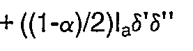
substituting and factoring out v=(Iaδ'δ'')/2 yields:

From the above expression it can be seen that the DC portion of the composite signal is independent of the transducer variation function α, thus the value of the DC portion after passing through low-pass filter 452 is used as a reference signal. The AC portion, variable with α is treated as the sensed signal. The AC portion is isolated in band-pass filter 450 and then passes throughAC detector 454 which yields its peak value: (2vα-v). This sensed value (2vα-v) is then normalized with respect to the reference value v by the simple ratio operation performed by thedivider circuitry 457. The output value of the divider circuitry (2α-1) is a function of α, independent of any intensity variation factors and can be further processed to yield α and/or the value of the sensed parameter. - Again, it is pointed out that the signals and related processing for the embodiments earlier-described with reference to FIGURES 8,9,10 and 11 can also be utilized with the differential type transducer just described.
- For the above-described embodiments,
sensor units - It is to be clearly understood by those skilled in the art that the invention is not limited to the embodiments described above. Rather, the scope of the invention is to be interpreted only in conjunction with the appended claims.
Claims (7)
- A fibre optic sensing system comprising an optical signal source (10,11) providing a signal (12) on a fibre-optic waveguide (14), a splitter (18) dividing the signal along first (24) and second (26) paths of different optical lengths whereby one portion is delayed with respect to the other, a coupler (32) combining the signal portions on to a single path (34), and a signal receiver (36) characterised in that
a transducer (28) of a kind capable of measuring a continuously variable parameter is included in at least one of the first and second paths, the signal from the receiver is processed by a signal processor (38) including separating means (42,44,46) for separating the delayed signal portion from the undelayed signal portion, and a divider for dividing one signal portion by the other to obtain an output signal representing the ratio of their amplitudes. - A fibre-optic sensing system according to claim 1 in which the first and second paths are terminated by reflectors (84), the splitter (19) acting as the coupler for the reflected signal portions, and in which means (88) is provided for separating the reflected signal (86) from the incident signal (12) and directing it to the receiver (36).
- A fibre-optic sensing system according to claim 1 or claim 2 in which the signal source generates a light pulse signal and the signal processor (38) includes gating means (46) directing the signal portions each to a separate sample-and-hold circuit (42,44), and the divider (57) divides an output signal of one of the sample-and-hold circuits by an output signal of the other.
- A fibre-optic sensing system comprising an optical signal source (110,111; 210,211; 310,311) providing a signal (112;212) on a fibre-optic wave guide (114;214), a splitter (118;218;318) dividing the signal along first (124;224;324) and second (126; 226;326) paths of different optical lengths whereby one portion is delayed with respect to the other, a coupler (132;232;332) combining the signal portions on to a single path (134;234;334) and a signal receiver (136;236;336) characterised in that a transducer (128) of a kind capable of measuring a continuously variable parameter is included in at least one of the first and second paths, said signal source (110,111;210,211;310,311) is arranged to generate an optical signal (112) having a periodic component, the delay introduced by the difference in optical lengths of said paths (124,126;224,226;324,326) is selected to cause interference between the delayed and undelayed portions of the periodic component of said signal and the signal from the receiver (136;236;336) is processed by a signal processor including filter means (150,152;280,282;366,368) arranged to separate two components of the received signal and to apply the sum and difference of said components to the respective inputs of a divider (157;257;357) to obtain an output signal representing the ratio of said sum and difference.
- A fibre-optic sensing system according to claim 4 in which the signal source (210,211;310,311) generates an oscillating signal that modulates a light signal with a signal, which is the sum of a signal having a period twice that of the delay and an even harmonic thereof, and the signal processor includes filters (266,268;366,368) providing outputs whose sum and difference (256,258) are applied to the inputs of said divider (257;357).
- A fibre-optic sensing system according to any preceding claim in which the transducer (428) is a differential transducer having two optical channels, one of which is included in the first path (424) and the other in the second path.
- A fibre-optic sensing system according to claim 4 in which the signal source (210,211) generates a first and a second oscillating signal to modulate a light signal, the first oscillating signal having a period twice that of the delay and the second oscillating signal being an even harmonic of the first, the signal source including switch means (274,275) for alternately directing either the light signal modulated by the first oscillating signal or the light signal modulated by the second oscillating signal to the sensor, and in which the signal processor includes an AC detector circuit (278) connected to the receiver signal and switching means (276) for alternately directing a signal from the AC detector circuit to separate sample-and-hold circuits (280,282), providing outputs whose sum and difference (256,258) are applied to the divider (257).
Priority Applications (1)
| Application Number | Priority Date | Filing Date | Title |
|---|---|---|---|
| AT86301256T ATE64457T1 (en) | 1985-02-22 | 1986-02-21 | TIME FIELD INTENSITY NORMALIZATION FOR OPTICAL FIBER DETECTOR. |
Applications Claiming Priority (2)
| Application Number | Priority Date | Filing Date | Title |
|---|---|---|---|
| US704324 | 1985-02-22 | ||
| US06/704,324 US4681395A (en) | 1985-02-22 | 1985-02-22 | Time-domain intensity normalization for fiber optic sensing |
Publications (3)
| Publication Number | Publication Date |
|---|---|
| EP0192490A2 EP0192490A2 (en) | 1986-08-27 |
| EP0192490A3 EP0192490A3 (en) | 1987-11-19 |
| EP0192490B1 true EP0192490B1 (en) | 1991-06-12 |
Family
ID=24829004
Family Applications (1)
| Application Number | Title | Priority Date | Filing Date |
|---|---|---|---|
| EP86301256A Expired - Lifetime EP0192490B1 (en) | 1985-02-22 | 1986-02-21 | Time-domain intensity normalization for fiber optic sensing |
Country Status (4)
| Country | Link |
|---|---|
| US (1) | US4681395A (en) |
| EP (1) | EP0192490B1 (en) |
| AT (1) | ATE64457T1 (en) |
| DE (1) | DE3679686D1 (en) |
Families Citing this family (22)
| Publication number | Priority date | Publication date | Assignee | Title |
|---|---|---|---|---|
| US4789240A (en) * | 1985-05-28 | 1988-12-06 | Litton Systems, Inc. | Wavelength switched passive interferometric sensor system |
| US4844573A (en) * | 1987-05-22 | 1989-07-04 | Aster Corporation | Electro-optical converter including ridgid support for optical fiber coupler, telephone set using the coupler and method of making same |
| DE3717687C1 (en) * | 1987-05-26 | 1988-12-01 | Messerschmitt Boelkow Blohm | Fiber optic actuator |
| US4893352A (en) * | 1987-06-30 | 1990-01-09 | Massachusetts Institute Of Technology | Optical transmitter of modulated signals |
| US4818064A (en) * | 1987-09-24 | 1989-04-04 | Board Of Trustees Stanford Junior University | Sensor array and method of selective interferometric sensing by use of coherence synthesis |
| US4930862A (en) * | 1988-01-20 | 1990-06-05 | The Babcock & Wilcox Company | Fiberoptic microbend accelerometer |
| US4918373A (en) * | 1988-03-18 | 1990-04-17 | Hughes Aircraft Company | R.F. phase noise test set using fiber optic delay line |
| DE3906118A1 (en) * | 1989-02-28 | 1990-08-30 | Bosch Gmbh Robert | DEVICE FOR INTERFEROMETRIC DETECTION OF SURFACE STRUCTURES |
| US4890893A (en) * | 1989-03-02 | 1990-01-02 | Bell Communications Research, Inc. | Dark fiber switched bandwidth filter |
| JP3162364B2 (en) * | 1990-10-15 | 2001-04-25 | 住友電気工業株式会社 | Optical sensor device |
| US5196694A (en) * | 1991-05-13 | 1993-03-23 | The Babcock & Wilcox Company | Temperature compensated self-referenced fiber optic microbend pressure transducer |
| US5258614A (en) * | 1991-05-13 | 1993-11-02 | The Babcock & Wilcox Company | Optical fiber loop temperature sensor |
| US5275053A (en) * | 1991-08-21 | 1994-01-04 | Fiberoptic Sensor Technologies, Inc. | Fiber optic pressure sensor systems |
| US5214729A (en) * | 1991-12-31 | 1993-05-25 | Gte Laboratories Incorporated | Dynamic optical data buffer |
| US5392655A (en) * | 1993-03-23 | 1995-02-28 | Eldec Corporation | Optical pickup and signal analyzing system for mass flowmeters |
| US5572350A (en) * | 1994-03-31 | 1996-11-05 | Lucent Technologies Inc. | Method and apparatus to compensate for differential attenuation in an optical time slot interchanger |
| AUPN329295A0 (en) * | 1995-05-31 | 1995-06-22 | University Of Sydney, The | Fibre optic transducer |
| US6305227B1 (en) * | 1998-09-02 | 2001-10-23 | Cidra Corporation | Sensing systems using quartz sensors and fiber optics |
| US7038188B2 (en) * | 2003-04-11 | 2006-05-02 | Hewlett-Packard Development Company, Lp. | Non-demolition photon detector that preserves input state characteristics |
| US7713196B2 (en) | 2007-03-09 | 2010-05-11 | Nellcor Puritan Bennett Llc | Method for evaluating skin hydration and fluid compartmentalization |
| US8560059B2 (en) * | 2007-03-09 | 2013-10-15 | Covidien Lp | System and methods for optical sensing and drug delivery using microneedles |
| CN103175555B (en) * | 2013-03-01 | 2015-04-01 | 浙江大学 | Multi-parameter distributed fiber-optic sensor based on multi-mechanism fusion |
Family Cites Families (11)
| Publication number | Priority date | Publication date | Assignee | Title |
|---|---|---|---|---|
| US4089584A (en) * | 1976-10-29 | 1978-05-16 | Northrop Corporation | Multiple station multiplexed communications link employing a single optical fiber |
| GB1540907A (en) * | 1976-12-07 | 1979-02-21 | Standard Telephones Cables Ltd | System for obtaining data from a plurality of condition responsive optical devices |
| US4420752A (en) * | 1978-03-20 | 1983-12-13 | Murray W. Davis | Real-time parameter sensor-transmitter |
| US4334781A (en) * | 1979-06-08 | 1982-06-15 | Tokyo Shibaura Denki Kabushiki Kaisha | Optical sensing system |
| US4313192A (en) * | 1979-09-11 | 1982-01-26 | Hydroacoustics, Inc. | Optical transducer array system |
| US4294513A (en) * | 1979-09-11 | 1981-10-13 | Hydroacoustics Inc. | Optical sensor system |
| EP0034107A1 (en) * | 1980-02-11 | 1981-08-19 | United Technologies Corporation | Optical encoder using time domain multi-plexer |
| FR2490432A1 (en) * | 1980-09-12 | 1982-03-19 | Lignes Telegraph Telephon | DEVICE FOR SEPARATING TWO LIGHT SIGNALS ISSUED BY SOURCES OF DIFFERENT WAVE LENGTHS, AND TRANSMITTED ON THE SAME OPTICAL FIBER, AND RECEIVER COMPRISING SUCH A DEVICE |
| US4375680A (en) * | 1981-01-16 | 1983-03-01 | Mcdonnell Douglas Corporation | Optical acoustic sensor |
| US4432599A (en) * | 1981-03-27 | 1984-02-21 | Sperry Corporation | Fiber optic differential sensor |
| US4436995A (en) * | 1981-06-29 | 1984-03-13 | General Electric Company | Fiber optics transducers for sensing parameter magnitude |
-
1985
- 1985-02-22 US US06/704,324 patent/US4681395A/en not_active Expired - Fee Related
-
1986
- 1986-02-21 AT AT86301256T patent/ATE64457T1/en not_active IP Right Cessation
- 1986-02-21 DE DE8686301256T patent/DE3679686D1/en not_active Expired - Lifetime
- 1986-02-21 EP EP86301256A patent/EP0192490B1/en not_active Expired - Lifetime
Also Published As
| Publication number | Publication date |
|---|---|
| ATE64457T1 (en) | 1991-06-15 |
| EP0192490A3 (en) | 1987-11-19 |
| US4681395A (en) | 1987-07-21 |
| DE3679686D1 (en) | 1991-07-18 |
| EP0192490A2 (en) | 1986-08-27 |
Similar Documents
| Publication | Publication Date | Title |
|---|---|---|
| US4681395A (en) | Time-domain intensity normalization for fiber optic sensing | |
| US4552457A (en) | Fiber optic interferometer using two wavelengths or variable wavelength | |
| KR870001580B1 (en) | Passive interferometric sensor arrays | |
| US4320475A (en) | Monomodal optical fibre hydrophone operating by the elastooptical effect | |
| US4356396A (en) | Fiber optical measuring device with compensating properties | |
| US4297887A (en) | High-sensitivity, low-noise, remote optical fiber | |
| US4363114A (en) | Low noise remote optical fiber sound detector | |
| US4759627A (en) | Fibre-optic interferometer | |
| US4853534A (en) | Optical fiber sensing system | |
| US4740081A (en) | Optical measuring apparatus | |
| US4694243A (en) | Optical measurement using polarized and unpolarized light | |
| KR860006690A (en) | Coherent Distribution Detector and Method Using Short Interference Length Source | |
| WO1998058285A1 (en) | Integrated optical waveguide system | |
| NO834587L (en) | IMPROVED FIBER OPTICAL SENSOR FOR DETECTING A SURFACE SMALL MOVE | |
| US6208129B1 (en) | Optical method and arrangement for measuring a periodic value having at least one frequency component | |
| JPH01238297A (en) | Optical fiber hydrophone and antenna connected to a series of hydrophones | |
| CN109696418A (en) | A kind of heterodyne balance detection system and detection method applied to the direct absorption process of TDLAS under low signal-to-noise ratio | |
| US4430565A (en) | Correlating fiber optical measuring device | |
| EP0306227B1 (en) | Fiber optic sensor | |
| GB2046434A (en) | Optical-fibre interferometric gyrometer | |
| EP0257959A2 (en) | Optical fibre measurement apparatus and method | |
| CA2593001A1 (en) | Angular grating bragg refractometer using optical power diffracted to a continuum of radiative modes | |
| KR100874428B1 (en) | Fiber Optic Sensor System Using Hybrid Interferometer | |
| EP0397636B1 (en) | Device and procedure for measuring with optical fibre sensors, and sensor utilised therewith | |
| SU1277733A1 (en) | Fibe-optics measuring device |
Legal Events
| Date | Code | Title | Description |
|---|---|---|---|
| PUAI | Public reference made under article 153(3) epc to a published international application that has entered the european phase |
Free format text: ORIGINAL CODE: 0009012 |
|
| AK | Designated contracting states |
Kind code of ref document: A2 Designated state(s): AT BE CH DE FR GB IT LI LU NL SE |
|
| RAP1 | Party data changed (applicant data changed or rights of an application transferred) |
Owner name: ELDEC CORPORATION |
|
| PUAL | Search report despatched |
Free format text: ORIGINAL CODE: 0009013 |
|
| AK | Designated contracting states |
Kind code of ref document: A3 Designated state(s): AT BE CH DE FR GB IT LI LU NL SE |
|
| 17P | Request for examination filed |
Effective date: 19880512 |
|
| 17Q | First examination report despatched |
Effective date: 19890802 |
|
| GRAA | (expected) grant |
Free format text: ORIGINAL CODE: 0009210 |
|
| AK | Designated contracting states |
Kind code of ref document: B1 Designated state(s): AT BE CH DE FR GB IT LI LU NL SE |
|
| PG25 | Lapsed in a contracting state [announced via postgrant information from national office to epo] |
Ref country code: SE Effective date: 19910612 Ref country code: NL Effective date: 19910612 Ref country code: LI Effective date: 19910612 Ref country code: CH Effective date: 19910612 Ref country code: BE Effective date: 19910612 Ref country code: AT Effective date: 19910612 |
|
| REF | Corresponds to: |
Ref document number: 64457 Country of ref document: AT Date of ref document: 19910615 Kind code of ref document: T |
|
| ITF | It: translation for a ep patent filed | ||
| REF | Corresponds to: |
Ref document number: 3679686 Country of ref document: DE Date of ref document: 19910718 |
|
| REG | Reference to a national code |
Ref country code: CH Ref legal event code: PL |
|
| ET | Fr: translation filed | ||
| NLV1 | Nl: lapsed or annulled due to failure to fulfill the requirements of art. 29p and 29m of the patents act | ||
| PG25 | Lapsed in a contracting state [announced via postgrant information from national office to epo] |
Ref country code: LU Free format text: LAPSE BECAUSE OF NON-PAYMENT OF DUE FEES Effective date: 19920229 |
|
| PLBE | No opposition filed within time limit |
Free format text: ORIGINAL CODE: 0009261 |
|
| STAA | Information on the status of an ep patent application or granted ep patent |
Free format text: STATUS: NO OPPOSITION FILED WITHIN TIME LIMIT |
|
| 26N | No opposition filed | ||
| PGFP | Annual fee paid to national office [announced via postgrant information from national office to epo] |
Ref country code: GB Payment date: 19960209 Year of fee payment: 11 |
|
| PGFP | Annual fee paid to national office [announced via postgrant information from national office to epo] |
Ref country code: FR Payment date: 19960229 Year of fee payment: 11 |
|
| PGFP | Annual fee paid to national office [announced via postgrant information from national office to epo] |
Ref country code: DE Payment date: 19960325 Year of fee payment: 11 |
|
| PG25 | Lapsed in a contracting state [announced via postgrant information from national office to epo] |
Ref country code: GB Effective date: 19970221 |
|
| GBPC | Gb: european patent ceased through non-payment of renewal fee |
Effective date: 19970221 |
|
| PG25 | Lapsed in a contracting state [announced via postgrant information from national office to epo] |
Ref country code: FR Effective date: 19971030 |
|
| PG25 | Lapsed in a contracting state [announced via postgrant information from national office to epo] |
Ref country code: DE Effective date: 19971101 |
|
| REG | Reference to a national code |
Ref country code: FR Ref legal event code: ST |
|
| PG25 | Lapsed in a contracting state [announced via postgrant information from national office to epo] |
Ref country code: IT Free format text: LAPSE BECAUSE OF NON-PAYMENT OF DUE FEES;WARNING: LAPSES OF ITALIAN PATENTS WITH EFFECTIVE DATE BEFORE 2007 MAY HAVE OCCURRED AT ANY TIME BEFORE 2007. THE CORRECT EFFECTIVE DATE MAY BE DIFFERENT FROM THE ONE RECORDED. Effective date: 20050221 |