EP0190438A2 - Compensation du décalage de la boucle d'asservissement de focalisation - Google Patents
Compensation du décalage de la boucle d'asservissement de focalisation Download PDFInfo
- Publication number
- EP0190438A2 EP0190438A2 EP85115698A EP85115698A EP0190438A2 EP 0190438 A2 EP0190438 A2 EP 0190438A2 EP 85115698 A EP85115698 A EP 85115698A EP 85115698 A EP85115698 A EP 85115698A EP 0190438 A2 EP0190438 A2 EP 0190438A2
- Authority
- EP
- European Patent Office
- Prior art keywords
- signal
- focus
- head
- supplying
- focus error
- Prior art date
- Legal status (The legal status is an assumption and is not a legal conclusion. Google has not performed a legal analysis and makes no representation as to the accuracy of the status listed.)
- Ceased
Links
Images
Classifications
-
- G—PHYSICS
- G11—INFORMATION STORAGE
- G11B—INFORMATION STORAGE BASED ON RELATIVE MOVEMENT BETWEEN RECORD CARRIER AND TRANSDUCER
- G11B7/00—Recording or reproducing by optical means, e.g. recording using a thermal beam of optical radiation by modifying optical properties or the physical structure, reproducing using an optical beam at lower power by sensing optical properties; Record carriers therefor
- G11B7/08—Disposition or mounting of heads or light sources relatively to record carriers
- G11B7/09—Disposition or mounting of heads or light sources relatively to record carriers with provision for moving the light beam or focus plane for the purpose of maintaining alignment of the light beam relative to the record carrier during transducing operation, e.g. to compensate for surface irregularities of the latter or for track following
- G11B7/0945—Methods for initialising servos, start-up sequences
-
- G—PHYSICS
- G11—INFORMATION STORAGE
- G11B—INFORMATION STORAGE BASED ON RELATIVE MOVEMENT BETWEEN RECORD CARRIER AND TRANSDUCER
- G11B7/00—Recording or reproducing by optical means, e.g. recording using a thermal beam of optical radiation by modifying optical properties or the physical structure, reproducing using an optical beam at lower power by sensing optical properties; Record carriers therefor
- G11B7/08—Disposition or mounting of heads or light sources relatively to record carriers
- G11B7/09—Disposition or mounting of heads or light sources relatively to record carriers with provision for moving the light beam or focus plane for the purpose of maintaining alignment of the light beam relative to the record carrier during transducing operation, e.g. to compensate for surface irregularities of the latter or for track following
- G11B7/094—Methods and circuits for servo offset compensation
-
- G—PHYSICS
- G11—INFORMATION STORAGE
- G11B—INFORMATION STORAGE BASED ON RELATIVE MOVEMENT BETWEEN RECORD CARRIER AND TRANSDUCER
- G11B7/00—Recording or reproducing by optical means, e.g. recording using a thermal beam of optical radiation by modifying optical properties or the physical structure, reproducing using an optical beam at lower power by sensing optical properties; Record carriers therefor
- G11B7/08—Disposition or mounting of heads or light sources relatively to record carriers
- G11B7/09—Disposition or mounting of heads or light sources relatively to record carriers with provision for moving the light beam or focus plane for the purpose of maintaining alignment of the light beam relative to the record carrier during transducing operation, e.g. to compensate for surface irregularities of the latter or for track following
- G11B7/0908—Disposition or mounting of heads or light sources relatively to record carriers with provision for moving the light beam or focus plane for the purpose of maintaining alignment of the light beam relative to the record carrier during transducing operation, e.g. to compensate for surface irregularities of the latter or for track following for focusing only
- G11B7/0917—Focus-error methods other than those covered by G11B7/0909 - G11B7/0916
- G11B2007/0919—Critical angle methods
-
- G—PHYSICS
- G11—INFORMATION STORAGE
- G11B—INFORMATION STORAGE BASED ON RELATIVE MOVEMENT BETWEEN RECORD CARRIER AND TRANSDUCER
- G11B7/00—Recording or reproducing by optical means, e.g. recording using a thermal beam of optical radiation by modifying optical properties or the physical structure, reproducing using an optical beam at lower power by sensing optical properties; Record carriers therefor
- G11B7/08—Disposition or mounting of heads or light sources relatively to record carriers
- G11B7/09—Disposition or mounting of heads or light sources relatively to record carriers with provision for moving the light beam or focus plane for the purpose of maintaining alignment of the light beam relative to the record carrier during transducing operation, e.g. to compensate for surface irregularities of the latter or for track following
- G11B7/0908—Disposition or mounting of heads or light sources relatively to record carriers with provision for moving the light beam or focus plane for the purpose of maintaining alignment of the light beam relative to the record carrier during transducing operation, e.g. to compensate for surface irregularities of the latter or for track following for focusing only
- G11B7/0909—Disposition or mounting of heads or light sources relatively to record carriers with provision for moving the light beam or focus plane for the purpose of maintaining alignment of the light beam relative to the record carrier during transducing operation, e.g. to compensate for surface irregularities of the latter or for track following for focusing only by astigmatic methods
Definitions
- This invention relates to servo loop control compensation and particularly to compensation in servo loops used by optical disk readers to maintain a light beam at best focus.
- Focus servo loop parameters change with time and use, causing the focusing system to servo to something other than best focus.
- the parameters most subject to change are the alignment of the optical paths associated with the quadrant diode detectors, gain of the diode signal preamplifiers, the laser beam profile, and overall response caused by foreign material contaminating the optical path.
- a quadrature diode detector technique is commonly used in optical reader heads to sense the laser or light beam reflected from the storage medium. Amplified output signals from the diodes are used to control the focus servo system to keep the laser dynamically focused on the medium. Close control of the focus in optical disk readers is necessary because the surface of the media has large runout relative to the one micron information bit size and the depth of field of the objective lens.
- U.S. Patent No. 4,368,526 shows a comparator for detecting the maximum peak of a differentiated read signal to establish the best focus in an open loop circuit.
- the focus control loop is closed to operate as a servo loop using a quadrant diode detecting scheme.
- U.S. Patent No. 4,243,848 shows a focus controller using photodetectors disposed at one of the conjugate planes of the converging lens and others on the focal plane of the objective lens.
- the diodes are aligned in a direction corresponding to the movement of the images of the information bits as they are read.
- a drive coil is controlled to maintain the light beam at best focus on the disk.
- U.S Patent No. 4,059,841 incorporated herein by reference, is directed to the use of four diodes arranged in quadrature to detect a projected quasi-punctiform spot for providing feedback to a focus control circuit.
- U.S. Patent No. 4,163,149 is directed to the correction of a focus control signal error component caused by tracking offsets. It uses quadrature diodes to provide a focus control signal derived from the difference of opposed diode signals and a compensation signal from the sum of adjacent diode signals. That is, a correction signal is supplied to compensate for the lateral movement of the focus circle on the diodes due to the action of the tracking movement.
- U.S. Patent No. 4,190,775 discloses an optical memory playback apparatus using an electroluminescent semiconductor element as both the source of light and the sensor.
- the semiconductor element is a three-mirror resonator constructed from an outer mirror and a laser element. Information is stored in the form of variations in the reflection factor of the outer mirrors and is read out by allowing the variation in the light output, viz., the presence or absence of oscillation, directed onto the semiconductor element which also acts as the sensor.
- a servo loop provides focusing compensation by furnishing a bias offset signal to the focus control signal, the magnitude being determined by sensing the focus error signal when the optical system is known to be at best focus. If the latter is not zero, a compensating signal of the same magnitude is subtracted from the error signal to force the resulting servo error signal to zero when the position of best focus is maintained.
- An optical disk data storage with a head having a lens arrangement for focusing a beam of radiant energy includes means for adjusting the focus and a servo loop for keeping the head at the best focus position.
- An indication is provided when the head is at its best focus position and the error signal is sensed in response to the indication signal.
- a correction signal is supplied having a magnitude equal to the error signal at best focus and is combined with the error signal to cancel out the sensed value.
- the system of the invention is simple and economical, adaptable to microprocessor control and shared circuitry which can be used with other parts of the system. It is usable with a wide range of error correction feedback schemes.
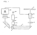
- FIG. 1 An optical system for a typical optical disk reader is illustrated in FIG. 1.
- a suitable source of light energy typically a solid state laser 11, generates a beam of light energy 12 which is passed through a collimator lens system 14 to form a collimated beam 15.
- the collimated beam 15 is directed to a polarizing prism 17 which includes a beam splitter 16.
- the beam 15 is thereby directed to the right and up through a quarter wave plate 18, circularly polarizing the beam, which is then passed through an object lens system 19 to focus on the reflective surface 10 of an optical disk.
- the light reflected from the disk surface 10 is passed back through the object lens 19 and through the quarter wave plate 18 to the polarizing prism 17.
- the beam splitter 16 allows a portion of the reflected beam to pass through the end of the polarizing prism 17 to a critical angle reflecting prism 19 which directs the portion of the reflected beam onto quadrature diodes 101.
- the output signals from the quadrature diodes 101 are coupled to a focus control unit 102 which supplies a drive signal to an object lens focus actuator 103.
- the laser beam is designed to be at best focus on the surface 10 when the drive signal has a value of zero, although this is not a necessary requirement.
- a monitor diode 104 detects a portion of the laser beam reflected from the beam splitter 16 back through the collimator lens 14 and through the solid state laser 11.
- the monitor diode 104 supplies a feedback control signal (not shown) that maintains the laser output power at a constant, predetermined value.
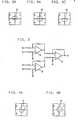
- the portion of the reflected laser beam from the optical disk surface 10 being read is directed onto a quadrature diode arrangement 101 shown in FIG. 2. Because of the lens arrangement and beam polarization, when the beam is focused on the disk surface 10, the reflected beam is a circle centered at the common junction point of the diodes. For example, in FIG. 2A, a reflected circular beam 20 is centered at the common junction point of four photodiodes A, B, C, and D. As a result, each of the photodiodes A-D receives an equal amount of energy and the voltage output signal from each diode is equal.
- the polarization and lens arrangement causes the beam shape to become a semicircle as illustrated in FIGS. 2B and 2C.
- a beam 21 is positioned so that the photodiodes A and B receive more energy than the photodiodes D and C as illustrated in FIG. 2B.
- the beam When the beam is out of focus in the other direction, e.g., away, the beam again becomes semicircular.
- the out-of-focus-away situation is illustrated as the semicircle 22 in FIG. 2C, positioned so that the photodiodes D and C receive more energy from the beam than do the photodiodes A and B.
- Vf O
- the signal Vf When the beam is out of focus in the toward direction to cause the beam on the photodiodes to appear as shown in FIG. 2B, the signal Vf will be some non-zero positive value. When out of focus in the other direction, i.e., the situation shown in FIG. 2C, the signal Vf will be some negative value.
- the laser beam object lens system 19 is mounted in a frame that is movable in either direction perpendicular to the focusing plane which, in the illustrative system being described, is defined by the disk surface 10.
- a system can use an electrical linear motor positioned as shown in FIG. 1 as the object lens focusing actuator 103.
- the focus signal, Vf represents the focus drive signal to keep the beam in focus. That is, when Vf is positive, the lens system 19 is offset in one direction and when Vf is negative, the lens system 19 is displaced in the other direction.
- a suitable focus control 102 is illustrated in FIG. 3.
- the focus voltage, Vf equal to Va + Vb - (Vd + Vc), can be rearranged to to take advantage of commercially available difference amplifiers.
- Equation (1) is implemented by the circuit illustrated in FIG. 3.
- the difference amplifiers 31-33 are coupled as shown using resistors having proper values which can readily be determined by one of ordinary skill in the art.
- the circuit output signal, Vf is coupled to the focus actuator 103 to supply a signal having the polarity and magnitude necessary to keep the laser beam at best focus on the disk surface 10 in the presence of run-out in the disk.
- a problem with this prior art system for keeping the laser beam in focus is that misalignment of the optical system can cause errors. For example, if the optical system is misaligned, the beam may not center on the diodes. This will cause the feedback correction signal, Vf, to be other than zero when the beam is at best focus.
- Another cause of error is change in circuit parameters, e.g., drift in the off-set voltages or gain of the difference amplifiers, or change in resistor values.
- FIG. 4 illustrates the situation where the optics have been misaligned so that the circle 40 produced at best focus does not fall on all diodes equally.
- the circle 40 in FIG. 4B will produce a focus actuator drive signal as if the system were out of focus in the toward direction. That is, the value of Va + Vb will exceed that of Vd + Vc. Therefore, the quality of the read signal will degrade to the point of being nonfunctional.
- the ellipse 41 in FIG. 4A will not produce the signal necessary to correct the corresponding out-of-focus condition.
- the invention to be described and illustrated below is directed to applying a correction to the focus drive signal when errors such as those described above begin to affect the accuracy of the focusing system.
- Adaptive focus error compensation requires some indication of optimum focus separate from the primary loop so that focus error signal misadjustment can be corrected.
- focus error signal misadjustment can be corrected.
- several other techniques are practical, all of which have been successfully used.
- An optically aligned head results in a DC voltage peak of either polarity, depending on amplifier inversions, of the data signal, which is the four-quadrant signal summed, when at best focus. This peak may be sensed as a best focus indicator.
- a test area of a track is reserved for best focus testing and written under varying conditions of focus.
- Optimum write focus which tends to be a more critical indicator than read focus, can then be determined from the resulting written area based on correlation with a known applied offset correction.
- track crossing signals occur prior to closing of the track-following loop.
- This signal may be utilized for best focus determination in at least two ways. The simplest of these, applicable to all types of tracks, is to look for a peak signal level as with the summed DC data signal. Grooved media produce a tracking signal with a "dog leg" as the laser spot tracks open-loop over the groove and land areas. This dog leg is a sensitive indicator of actual focus. When it is flattest or demonstrating a slight negative slope (depending on groove width, optical alignment, detector gains, and properly located with respect to signal peaks), the head is servoed to best focus.
- This best focus dog leg detection can be accomplished by digitizing the tracking error signal followed by an identification of the inflection points. After differentiation, lbcations of consecutive positive and negative peaks in time are compared, using amplitude comparators to separate major and minor peaks, simplifying timing logic for interpretation for identifying dog leg duration. This is described in more detail in U.S. Patent No. 4,059,841, incorporated herein by reference.
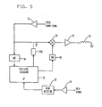
- FIG. 5 illustrates a preferred embodiment of the invention. All the devices used are well known in the art and are commercially available.
- the data signal is received and amplified by a data amplifier 51.
- the output signal from the data amplifier 51 is coupled to the input of a peak detector 52, which produces an output signal when the amplified data signal reaches its peak value, to the bias level generator 55, which is preferably an appropriately programmed microcomputer.
- the focus error signal is received by an amplifier 53 and the amplified focus error signal is coupled to the bias level generator 55 through an analog-to-digital converter 54.
- the amplified focus error signal is also coupled to a mixer 56, the output supplying a signal via a focus amplifier 57 to the focus actuator 58.
- the other input to the mixer 56 is an output signal from the bias level generator 55 through a digital-to-analog converter 59.
- a switch 50 is controlled by the bias level generator 55 to decouple the focus error signal from the mixer 56.
- the focus actuator 58 operates the lens focusing system as shown in FIG. 1.
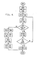
- the program for controlling the microcomputer comprising the bias level generator 55 is shown in the flow chart in FIG. 6.
- This program operates the bias level generator as follows. Initially, the switch 50 is opened, typically by a coil as in a relay as shown or using a solid state switch, and the output signal via the DAC 59 is used to position the focus actuator at one limit of its travel. The output signal to the DAC 59 is then driven to the other limit in a stepwise fashion while the amplified focus error signal is sensed by the bias level generator 55 via the ADC 54.
- the peak detector 52 When the peak detector 52 indicates that the data signal has reached a peak, it supplies a signal to the bias level generator 55. When it is sensed, the value of the output signal from the ADC 54 is stored.
- the program then causes the bias level generator to supply an output value to the DAC 59 which has the same amplitude as the focus error signal stored at the occurrence of the data signal peak.
- the polarity of the output signal from the DAC 59 is, however, opposite from that of the stored focus error signal.
- the polarities of the two signals to the mixer can have the same polarities provided that the mixer 56 is of the subtractive type.
- the switch 50 is then closed so that both signals are coupled to the mixer 56.
- the undesired error in the focus error signal is cancelled and the output signal from the mixer 56 has a value of zero when the lens system is positioned at best focus.
- the program can also be represented by a design language from which programmers of ordinary skill in the art can write the program details for use on the particular microcomputer used to implement the invention.
- the choice of a suitable microcomputer is within the skill of the art and depends on the speed, capacity, and level of mathematical operations required for the particular system to be implemented. For example, in the presently illustrated embodiment of the invention, operations other than those to practice the invention would probably be implemented using a microcomputer. Such operations would include the timing and generation of command signals to the components comprising the optical reader and sensing input signals necessary for proper operation of the system. For example, a switch would likely be provided to supply a signal that indicates the door through which a disk is placed on the spindle is open.
- a command received from a processor to position the head and to read the data would entail starting the motor and positioning the head.
- the first step might be to sense that the door is shut and provide an error indication that the door is open. The operator would have to close the door before the microprocessor would initiate the steps to read the data.
- the system might also be used to perform the function of supplying the focus signal, shown in FIG. 3 as an analog system.
- the program for implementing the present invention would likely be included as a subroutine which could be invoked automatically when read errors were detected or manually by the operator.
- microprocessors e.g., a Z80 (Zilog, Inc.), an 8080 (Intel, Inc.), a MC6800 (Motorola, Inc.), or a COSMAC 1802 (RCA Corp.).
- Z80 Zero-Zilog, Inc.
- 8080 Intel, Inc.
- MC6800 Motorola, Inc.
- COSMAC 1802 COSMAC 1802
- Each of the microprocessors uses a different instruction set (although the Z80 and 8080 instruction sets are somewhat compatible). Therefore, the exact program depends on the particular microprocessor used.
- Program design languages have been used for some time in the art to describe the details of a program in sufficient detail for the implementer to program the particular microprocessor used. These design languages also permit the program to be systematically designed from the top down leaving the details until last by use of functional statements and step-wise refinement. For implementation of the present invention, a suitable program could be written from the following design language.
Applications Claiming Priority (2)
| Application Number | Priority Date | Filing Date | Title |
|---|---|---|---|
| US69851885A | 1985-02-04 | 1985-02-04 | |
| US698518 | 1985-02-04 |
Publications (2)
| Publication Number | Publication Date |
|---|---|
| EP0190438A2 true EP0190438A2 (fr) | 1986-08-13 |
| EP0190438A3 EP0190438A3 (en) | 1987-08-12 |
Family
ID=24805600
Family Applications (1)
| Application Number | Title | Priority Date | Filing Date |
|---|---|---|---|
| EP85115698A Ceased EP0190438A3 (en) | 1985-02-04 | 1985-12-10 | Focus servo loop off-set compensation |
Country Status (2)
| Country | Link |
|---|---|
| EP (1) | EP0190438A3 (fr) |
| JP (1) | JPS61177646A (fr) |
Cited By (7)
| Publication number | Priority date | Publication date | Assignee | Title |
|---|---|---|---|---|
| EP0247829A1 (fr) * | 1986-05-26 | 1987-12-02 | Pioneer Electronic Corporation | Méthode et appareil pour corriger le gain de rétroaction d'une servo-boucle à réglage fin |
| EP0260987A2 (fr) * | 1986-09-19 | 1988-03-23 | Pioneer Electronic Corporation | Circuit de compensation d'un écart permanent dans un dispositif d'asservissement à commande précise |
| EP0290882A1 (fr) * | 1987-05-09 | 1988-11-17 | Deutsche Thomson-Brandt GmbH | Appareil pour la reproduction de données |
| EP0309719A1 (fr) * | 1987-09-30 | 1989-04-05 | Deutsche Thomson-Brandt GmbH | Appareil pour reproduire des données |
| EP0348233A2 (fr) * | 1988-06-23 | 1989-12-27 | Sharp Kabushiki Kaisha | Dispositif de régulation à réaction pour appareil d'enregistrement et de reproduction optique |
| DE4102857A1 (de) * | 1991-01-31 | 1992-08-06 | Thomson Brandt Gmbh | Verfahren zum fokussieren eines lichtstrahls |
| EP0350939B1 (fr) * | 1988-07-15 | 1992-09-23 | Deutsche Thomson-Brandt GmbH | Méthode et dispositif de branchement pour la compensation des écarts de tension dans un circuit pour la mise au point et/ou le suivi de piste |
Citations (11)
| Publication number | Priority date | Publication date | Assignee | Title |
|---|---|---|---|---|
| FR2325987A1 (fr) * | 1975-09-29 | 1977-04-22 | Thomson Brandt | Dispositif de lecture optique d'un enregistrement |
| FR2360150A1 (fr) * | 1976-07-28 | 1978-02-24 | Hitachi Ltd | Appareil de mise au point automatique |
| US4190775A (en) * | 1975-02-18 | 1980-02-26 | Agency Of Industrial Science & Technology | Optical memory playback apparatus |
| US4243848A (en) * | 1978-03-20 | 1981-01-06 | Teac Corporation | Focus control system for optical read-out apparatus |
| DE3048708A1 (de) * | 1979-12-28 | 1981-10-15 | Matsushita Electric Industrial Co., Ltd., Kadoma, Osaka | Servosteuersystem fuer optisches lesen und aufzeichnen |
| DE3227654A1 (de) * | 1981-07-24 | 1983-02-17 | Sony Corp., Tokyo | Optische informationsaufzeichnungs-/wiedergabe-einrichtung |
| JPS5853030A (ja) * | 1981-09-22 | 1983-03-29 | Mitsubishi Electric Corp | 光学再生装置の追跡装置 |
| JPS5883338A (ja) * | 1981-11-10 | 1983-05-19 | Teac Co | 光学的情報記録装置における記録用光ビームの最適フオーカス状態を得るための方法 |
| JPS58121139A (ja) * | 1982-01-11 | 1983-07-19 | Olympus Optical Co Ltd | 自動フオ−カス制御装置 |
| JPS58212633A (ja) * | 1982-06-04 | 1983-12-10 | Nec Corp | フオ−カス制御装置 |
| JPS598144A (ja) * | 1982-07-05 | 1984-01-17 | Trio Kenwood Corp | 光学的情報読取装置 |
Family Cites Families (1)
| Publication number | Priority date | Publication date | Assignee | Title |
|---|---|---|---|---|
| JPS59188845A (ja) * | 1983-04-08 | 1984-10-26 | Onkyo Corp | 光ピツクアツプ |
-
1985
- 1985-11-13 JP JP25300885A patent/JPS61177646A/ja active Granted
- 1985-12-10 EP EP85115698A patent/EP0190438A3/en not_active Ceased
Patent Citations (11)
| Publication number | Priority date | Publication date | Assignee | Title |
|---|---|---|---|---|
| US4190775A (en) * | 1975-02-18 | 1980-02-26 | Agency Of Industrial Science & Technology | Optical memory playback apparatus |
| FR2325987A1 (fr) * | 1975-09-29 | 1977-04-22 | Thomson Brandt | Dispositif de lecture optique d'un enregistrement |
| FR2360150A1 (fr) * | 1976-07-28 | 1978-02-24 | Hitachi Ltd | Appareil de mise au point automatique |
| US4243848A (en) * | 1978-03-20 | 1981-01-06 | Teac Corporation | Focus control system for optical read-out apparatus |
| DE3048708A1 (de) * | 1979-12-28 | 1981-10-15 | Matsushita Electric Industrial Co., Ltd., Kadoma, Osaka | Servosteuersystem fuer optisches lesen und aufzeichnen |
| DE3227654A1 (de) * | 1981-07-24 | 1983-02-17 | Sony Corp., Tokyo | Optische informationsaufzeichnungs-/wiedergabe-einrichtung |
| JPS5853030A (ja) * | 1981-09-22 | 1983-03-29 | Mitsubishi Electric Corp | 光学再生装置の追跡装置 |
| JPS5883338A (ja) * | 1981-11-10 | 1983-05-19 | Teac Co | 光学的情報記録装置における記録用光ビームの最適フオーカス状態を得るための方法 |
| JPS58121139A (ja) * | 1982-01-11 | 1983-07-19 | Olympus Optical Co Ltd | 自動フオ−カス制御装置 |
| JPS58212633A (ja) * | 1982-06-04 | 1983-12-10 | Nec Corp | フオ−カス制御装置 |
| JPS598144A (ja) * | 1982-07-05 | 1984-01-17 | Trio Kenwood Corp | 光学的情報読取装置 |
Non-Patent Citations (5)
| Title |
|---|
| PATENT ABSTRACTS OF JAPAN, vol. 7, no. 138 (P-204)[1283], 16th June 1983; & JP-A-58 053 030 (MITSUBISHI DENKI K.K.) 29-03-1983 * |
| PATENT ABSTRACTS OF JAPAN, vol. 7, no. 180 (P-215)[1325], 9th August 1983; & JP-A-58 083 338 (TEAC K.K.) 19-05-1983 * |
| PATENT ABSTRACTS OF JAPAN, vol. 7, no. 234 (P-230)[1379], 18th October 1983; & JP-A-58 121 139 (OLYMPUS KOGAKU KOGYO K.K.) 19-07-1983 * |
| PATENT ABSTRACTS OF JAPAN, vol. 8, no. 65 (P-263)[1502], 27th March 1984; & JP-A-58 212 633 (NIPPON DENKI K.K.) 10-12-1983 * |
| PATENT ABSTRACTS OF JAPAN, vol. 8, no. 97 (P-272)[1534], 8th May 1984; & JP-A-59 008 144 (TRIO K.K.) 17-01-1984 * |
Cited By (10)
| Publication number | Priority date | Publication date | Assignee | Title |
|---|---|---|---|---|
| EP0247829A1 (fr) * | 1986-05-26 | 1987-12-02 | Pioneer Electronic Corporation | Méthode et appareil pour corriger le gain de rétroaction d'une servo-boucle à réglage fin |
| EP0260987A2 (fr) * | 1986-09-19 | 1988-03-23 | Pioneer Electronic Corporation | Circuit de compensation d'un écart permanent dans un dispositif d'asservissement à commande précise |
| EP0260987A3 (en) * | 1986-09-19 | 1989-07-19 | Pioneer Electronic Corporation | Offset compensating circuit, in fine control servo device |
| EP0290882A1 (fr) * | 1987-05-09 | 1988-11-17 | Deutsche Thomson-Brandt GmbH | Appareil pour la reproduction de données |
| EP0309719A1 (fr) * | 1987-09-30 | 1989-04-05 | Deutsche Thomson-Brandt GmbH | Appareil pour reproduire des données |
| EP0348233A2 (fr) * | 1988-06-23 | 1989-12-27 | Sharp Kabushiki Kaisha | Dispositif de régulation à réaction pour appareil d'enregistrement et de reproduction optique |
| EP0348233A3 (en) * | 1988-06-23 | 1990-11-14 | Sharp Kabushiki Kaisha | Feedback control apparatus in an optical recording and reproducing device |
| US5084848A (en) * | 1988-06-23 | 1992-01-28 | Sharp Kabushiki Kaisha | Feedback control apparatus in an optical recording and reproducing device |
| EP0350939B1 (fr) * | 1988-07-15 | 1992-09-23 | Deutsche Thomson-Brandt GmbH | Méthode et dispositif de branchement pour la compensation des écarts de tension dans un circuit pour la mise au point et/ou le suivi de piste |
| DE4102857A1 (de) * | 1991-01-31 | 1992-08-06 | Thomson Brandt Gmbh | Verfahren zum fokussieren eines lichtstrahls |
Also Published As
| Publication number | Publication date |
|---|---|
| EP0190438A3 (en) | 1987-08-12 |
| JPH0520816B2 (fr) | 1993-03-22 |
| JPS61177646A (ja) | 1986-08-09 |
Similar Documents
| Publication | Publication Date | Title |
|---|---|---|
| US4823330A (en) | Focus servo loop off-set compensation | |
| US5881034A (en) | Apparatus for driving objective lens | |
| US5136559A (en) | Optical information recording and reproducing apparatus using tracking mirror | |
| KR100327748B1 (ko) | 초점제어방법및광디스크장치 | |
| US4607357A (en) | Optical pickup apparatus for recorded information with tilt indication | |
| US4899327A (en) | Focus servo loop correction | |
| US4975895A (en) | Track servo control system for optical disk apparatus | |
| CA1314983C (fr) | Appareil optique de traitement d'information pouvant maintenir un dispositif optique dans une situation predeterminee en cas de defaillance de la commande de centrage ou de focalisation | |
| EP0512616B1 (fr) | Dispositif de balayage optique | |
| JPS61204840A (ja) | 光学的情報記録再生装置 | |
| EP0190438A2 (fr) | Compensation du décalage de la boucle d'asservissement de focalisation | |
| US5146442A (en) | Method and apparatus for effecting at least one of tracking and servo control when an error signal passes a zero-cross point and reaches a predetermined non-zero value | |
| US5862111A (en) | Optical disk device which performs auto gain control process on servo signals which perform illuminating control of a light beam on the disk's recording surface | |
| US6266301B1 (en) | Optical storage device and optical head having TES compensation shift signal compensation | |
| US5572495A (en) | Optical recording and reproducing system using servo control, switches and control circuitry | |
| US5293365A (en) | Track control circuit for optical card recording/reproducing apparatus | |
| EP0190439A2 (fr) | Correction de la boucle d'asservissement de focalisation | |
| EP0558293B1 (fr) | Méthode d'enregistrement/réproduction optique et appareil pour ceci | |
| US6522606B1 (en) | Optical pickup servo control apparatus with stored compensatory values | |
| US5361246A (en) | Optical information processing apparatus provided with means for detecting abnormality of focusing servo with a predetermined sensitivity | |
| US7206264B1 (en) | Method for regulating the tracking of a scanning device and drive for the same | |
| EP0456014B1 (fr) | Appareil d'enregistrement/de reproduction optique | |
| JP2774295B2 (ja) | 光学的情報記録再生装置 | |
| KR19990050071A (ko) | 포커스 바이어스 조정 장치 | |
| US7046609B2 (en) | Focus search method and reproducing apparatus |
Legal Events
| Date | Code | Title | Description |
|---|---|---|---|
| PUAI | Public reference made under article 153(3) epc to a published international application that has entered the european phase |
Free format text: ORIGINAL CODE: 0009012 |
|
| AK | Designated contracting states |
Kind code of ref document: A2 Designated state(s): DE FR GB |
|
| 17P | Request for examination filed |
Effective date: 19861212 |
|
| PUAL | Search report despatched |
Free format text: ORIGINAL CODE: 0009013 |
|
| AK | Designated contracting states |
Kind code of ref document: A3 Designated state(s): DE FR GB |
|
| 17Q | First examination report despatched |
Effective date: 19890127 |
|
| STAA | Information on the status of an ep patent application or granted ep patent |
Free format text: STATUS: THE APPLICATION HAS BEEN REFUSED |
|
| 18R | Application refused |
Effective date: 19910207 |
|
| RIN1 | Information on inventor provided before grant (corrected) |
Inventor name: RHOADES, MARK LEN Inventor name: CALL, MARK GREGORY Inventor name: ARTER, NELSON KAY |